300 GEORGE ST REDEVELOPMENT IMPACT OF PROPOSED BASEMENT EXCAVATION ON THE ANN STREET ONRAMP STRUCTURES
|
|
|
- Darcy Atkins
- 6 years ago
- Views:
Transcription

1 300 GEORGE ST REDEVELOPMENT IMPACT OF PROPOSED BASEMENT EXCAVATION ON THE ANN STREET ONRAMP STRUCTURES BONACCI GROUP DOCUMENT HISTORY ISSUE REVISION DATE AUTHOR REVIEWER Issued for DTMR Review A October 11, 2013 R. West RPEQ Issued for DA B November 1, 2013 R. West RPEQ J. Velosa RPEQ 2586 J. Velosa RPEQ 2586

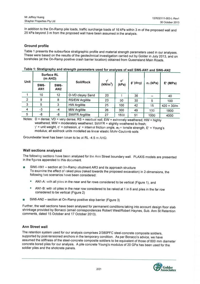
2 1 INTRODUCTION The proposed redevelopment of the old Supreme Court site in Brisbane, located at 300 George St, involves the construction of an integrated commercial, residential and retail development consisting of three high-rise towers, located over a common podium with seven levels of underground basement. The existing site is bounded by George St to the east, Adelaide St to the south, North Quay to the west and Ann St on the north. Aerial Photo of Existing Site Immediately adjacent to the existing site is the Ann Street on-ramp onto the Riverside Expressway, which consists of a single lane, five span continuous, post-tensioned curved concrete box girder bridge with insitu concrete abutments and approach structure at the Gorge St end. 2 SCOPE AND LIMITATIONS The purpose of this report is to identify the impacts on the existing Ann Street Bridge and supporting structures to enable the Department of Transport and Main Roads (TMR), to develop a set of compliance measures which would form part of the Development Application. TMR have advised ( on the 20/8/2013) that; the developers are to ensure that the displacements of footings / piles supporting existing bridges / on-ramp are such that the performance of these structures are not compromised; lateral displacements arising from excavations and how this will be managed should they be adverse and impair on the functionality of adjacent buildings and other road assets should be documented; 300 George St Redevelopment Impact of Basement Excavation on Ann Street On-Ramp 2
3 The main body of the Report discusses the overall impacts due to the excavation and proposes a way forward to reach approval for the Development. The detailed analysis and discussion is included in 3 main appendices as follows: Analysis of soil behavior and resulting movements on structures. Prepared by Golder Associates Analysis of the 5 span bridge deck, columns and Abutment A (River side). Prepared by Nick Stevens Consulting Analysis of Abutment B (George St side) and approach structure. Prepared by Bonacci This report is based on information currently available and may include further analysis on receipt of further information. The intention is however to inform TMR on our key findings at key stages in the process and assist TMR in drafting the relevant and appropriate conditions for the proposed development in a timely manner. It is understood that the On-ramp was temporarily closed to traffic in 2006, following the discovery of excessive twist in the box girder. The Report does not address the state of the structure as is, however it recognizes that the excavation impacts will add to the current status. Traffic loads were assumed to be those included in the prevailing Code at the time of construction of the bridge (early 1970), i.e T44. 3 ON-RAMP STRUCTURE The On-ramp structure is described in detail in Appendix C and drawings are included in Appendix D. The following details are of particular significance: The approach ramp from George St is a suspended slab/beam arrangement supported on side walls which in turn are supported on bored piles. These piles are found on low to medium strength weathered rock. The space underneath the slab is void. The River end of the approach structure is supported vertically on a pile cap which also supports the abutment. The support is via a sliding joint. The pile cap covers 6 raked and vertical bored piles. The abutment supports the end of the bridge girder via 2 pot bearings and a central restraint in both longitudinal and transverse directions The side walls of the approach structure and abutment wall are covered with a decorative concrete block veneer. The first bridge column coming from George St is supported on a high level pad footing. The remaining columns are on piles The Positive Stop Barrier constructed in 2009 is a separate steel portal frame supported on piles. Due to the flexibility of the frame it will not be further discussed in this report George St Redevelopment Impact of Basement Excavation on Ann Street On-Ramp 3
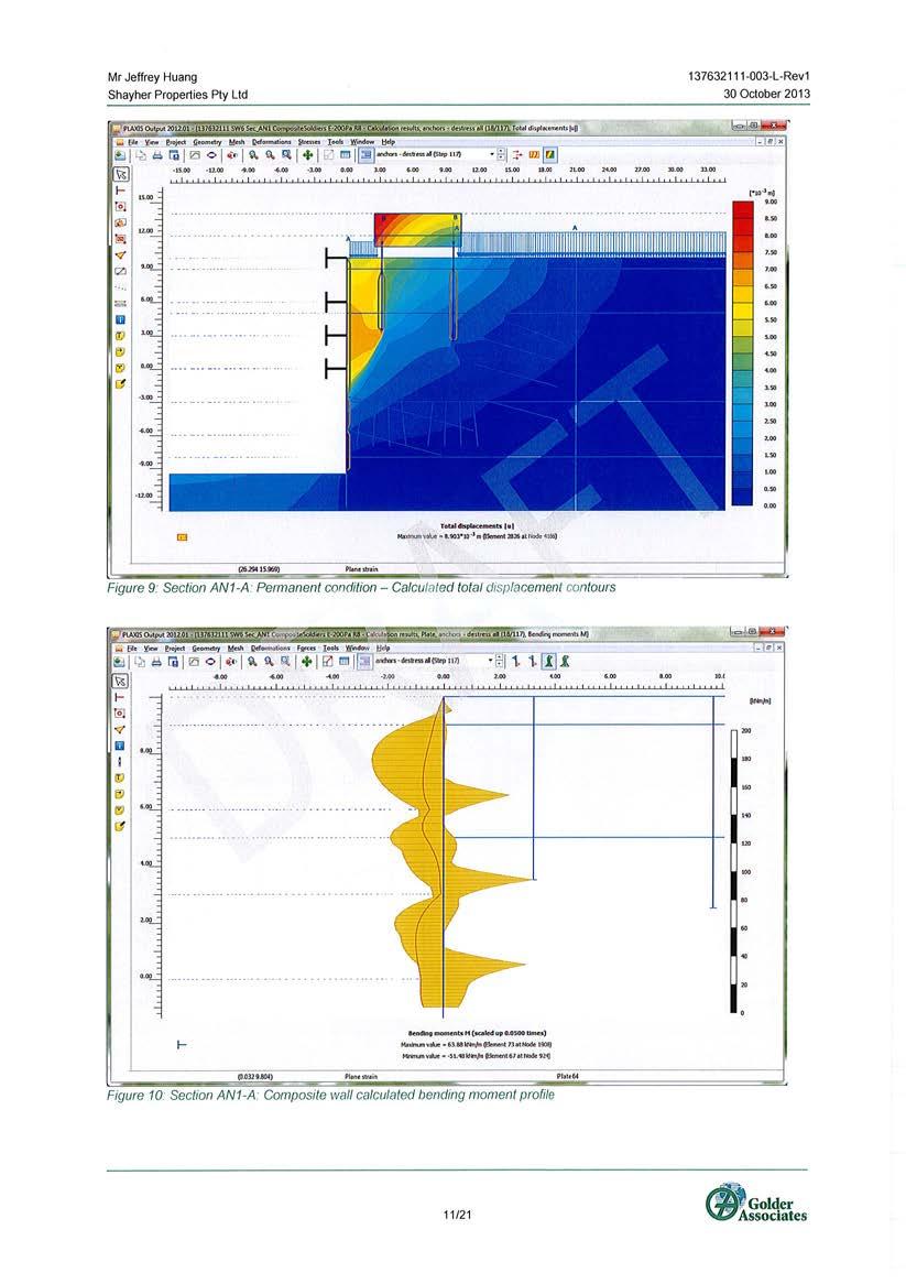
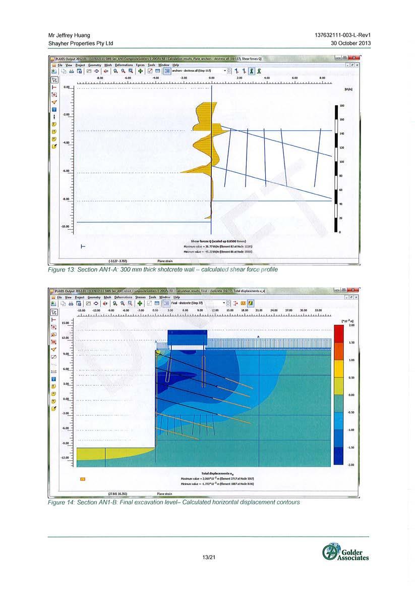
4 4 BASEMENT EXCAVATION IMPACT The proposed basement involves the construction of a composite steel soldier and shotcrete wall to retain the surface soils and medium-low strength rock, and a solid shotcrete wall facing to the more competent rock below. The wall is tied back progressively with stressed anchors as the excavation progresses. The lowest basement level B7 is approximately 20m below the surface. Appendix A gives further details on the excavation and retention. Impacts on the On-ramp are: Short term. As the excavation progresses the relaxation of the soil mass invariably causes settlement and horizontal displacement of the wall. This happens regardless of the amount of stressing used in the tie backs. The soil movement causes pile settlement and potentially horizontal displacement. More importantly is the potential differential settlement between piles which imposes additional stresses on the structure. Long term. The basement slabs, which prop the excavation in the long term, will undergo shrinkage and creep over time. Whilst the majority of the movement will occur in the initial, say 2 years, while the stressed anchors are still effective, a residual movement can be expected after that. This effect has been considered in our analysis 5 FINDINGS OF THE ANALYSIS Key findings are summarized below: Per Golders geotechnical analysis, dated 30/10/13 and attached in Appendix A, the expected maximum short term settlement is in the order of 2mm (where the wall is supported by the ground anchors) and 7mm maximum long term settlement, allowing for shrinkage of the basement slabs over 30 years. Our preliminary analysis has considered 10mm as differential settlement between piles to cater for uncertainty and cover the worst possible scenario. This movement is considered to be manageable, involving only light repair measures to the approach structure if it was to eventuate. For the Ann Street bridge girder, the impacts of a 20mm settlement has also been reviewed, with the results included in the separate report by Nick Stevens, attached in Appendix B. The current twisting of the bridge girder at Abutment B with the inside (North) bearing lifting during periods of high temperature will not be aggravated. This is because the abutment is almost certain to rotate in the other direction Lateral movement at abutment B will not impact the bridge deck. However a potential opening of the expansion joint at abutment A has to be addressed. 300 George St Redevelopment Impact of Basement Excavation on Ann Street On-Ramp 4
5 6 PREVENTATIVE MEASURES AND MONITORING OF BRIDGE STRUCTURES DURING EXCAVATION Although every effort has been made to protect these structures, it is possible that the resulting relaxation of the soil/rock around and under the existing Ann Street structures may result in settlements greater than the 10mm allowed for in our review. The approach adopted to minimize these risks and to rectify possible damage is as follows: 1. Design of the new basement such that potential soil movement is minimized Increasing perimeter wall stiffness alongside the ramp structure and providing additional soldiers in the vicinity of the bridge foundations Provide additional redundant ground anchors in the vicinity of the existing bridge to allow for additional prestress to be applied to the wall. 2. Design of the retention system and construction sequence to minimize movement Reduced spacing and higher stressing forces on the ground anchors Excavate the basement walls with hit and miss excavation to minimize movement of the unrestrained wall. To minimize the resulting movement in the wall due to shrinkage of the carpark slabs, a gap will be left between wall and slab, for as long as possible to allow the slabs to stabilize. This gap will be closed with a fine concrete mix as late as practical during the construction of the development (minimum of 18months, but possibly even later as this is not disruptive to progressing the basement construction). 3. Implement a monitoring programme Main Roads have requested that a comprehensive monitoring programme be implemented by an independent Consultant. It is assumed that movements to be measured would include vertical and lateral displacements as well as rotations and tilt. 4. Develop contingency plans to deal with worst case scenarios The structural review of the bridge deck and its bearings has concluded that: (i) the bridge deck can tolerate differential vertical deflection in the order of 10mm without being affected, and can accommodate a 20mm maximum settlement with minor impact. (ii) Possible twisting of the deck due to settlements of the piles would actually improve the current state of the bridge bearings. (iii) Lateral displacement can also be tolerated provided the existing bearings have sufficient reserve travel to accommodate the expected horizontal movement. Prior to commencing site activities it is envisaged that the current status of the bearings (at abutments and piers) will be surveyed and inspected. This would form part of the independent assessment and monitoring programme mentioned above. 300 George St Redevelopment Impact of Basement Excavation on Ann Street On-Ramp 5
6 In the unlikely event that the predicted displacements are exceeded and the deck performance is compromised, the bearings would need adjustment. The process to implement these adjustments would have to be developed with Main Roads in order to ultimately obtain their approval. A review of the Ann St Approach Structure has revealed that relatively small differential settlements between piles may overstress the walls and cause cracking in the walls of this structure. Although the walls have more than enough reserve structural capacity to support the design loads, the resulting cracks may make the structure more vulnerable to corrosion. Should the settlements of the piles exceed the allowable range, the strategy is to monitor the structure during excavation and to repair any cracks that may occur should the movements exceed the permissible values. This would involve removing and reinstating the existing block wall veneer and then injecting the cracks with an approved repair method. 7 CONCLUSIONS A detailed structural design review has been undertaken for the Ann Street bridge girder, abutment and approach structures for the case of a 10mm maximum vertical and horizontal displacement. This exceeds a maximum calculated displacement of 7mm as determined by Golders Associates in their report dated 30/1/13. A structural review of the bridge girder and abutment indicates that these structures can accommodate these displacements without distress, and potentially have sufficient capacity to accommodate up to 20mm displacement with minor impact. The approach structure is much more sensitive to differential settlements between the supporting piles, due to its very high stiffness, and may crack if the differential settlements exceed predictions. Should this occur, any cracking will not substantially reduce the load capacity of this structure, and is primarily a durability concern with any resulting damage be rectified to TMR s satisfaction. 300 George St Redevelopment Impact of Basement Excavation on Ann Street On-Ramp 6
7 8 APPENDIX A ANN ST BOUNDARY WALL ANALYSIS RESULTS GOLDER ASSOCIATES 300 George St Redevelopment Impact of Basement Excavation on Ann Street On-Ramp 7
8
9
10
11
12
13
14
15
16
17
18
19
20
21
22
23
24
25
26
27
28
29 9 APPENDIX B EFFECTS OF ABUTMENT SETTLEMENT ON ANN ST RAMP SUPERSTRUCTURE - NICK STEVENS CONSULTING 300 George St Redevelopment Impact of Basement Excavation on Ann Street On-Ramp 8
30 1/54 Kersley Rd Kenmore Q 4069 PO Box 655 Kenmore Q 4069 Ph M Report On Effects of Abutment Settlement on the Ann St Ramp Superstructure Client Project Bonacci Group (Qld) Pty Ltd 300 George St Ann St Ramp Abutment Issue Date 29 October 2013 Document No: NSC270-TR-02 Rev Introduction Bonacci are providing engineering services for the design of the proposed development at 300 George St. This site is immediately adjacent to the abutment for the Ann St access ramp onto the Riverside Expressway. This structure is a 5 span curved post tensioned concrete box girder. The excavation for the proposed development will extend to well below the founding levels for the Ann St Ramp abutment. Hence some movement of the abutment can be expected as a result of the excavation. Bonacci have engaged Dr Nick Stevens of Nick Stevens Consulting Pty Ltd (NSC) to investigate the effects of any settlement at the abutment on the bridge superstructure. A preliminary assessment of the issue has already been undertaken and is reported on in document NSC270-TR-01. That assessment indicated that the ramp would be relatively tolerant to small settlements at Abutment B. This assessment includes a more detailed analysis model. Also, as a result of geotechnical modeling by others, Bonacci have now provided design and extreme case settlements which will form the basis of the assessment. This report summarizes the results of the assessment. 2.0 Description of the Structure The structure is a 5 span, double cell concrete box girder. It is post tensioned, and was constructed in stages. The staged construction can be expected to have had an effect on the long term final stress state in the bridge. The Department of Transport and Main Roads (TMR) chainage for this structure increases from the river end to the city end so in accordance with standard practice, in this report, the abutment and pier numbering starts from the river end. Abutment A is Nick Stevens Consulting Pty Ltd ABN Nick Stevens BE PhD (Toronto) MIE Aust RPEQ
31 the column supporting the river end and Abutment B is the abutment on Ann St which is of interest. Pier 4 is the Pier on Ann St which also may be affected by the excavation. Abutment B is supported on piles, however Pier 4 is supported on a high level spread footing. The articulation of the superstructure is as follows: Abutment A: Two bearings effectively preventing twist about the bridge centre line. Free to move along bridge centre line, but restrained transversely. Piers 1 to 4: Vertical support only free to move longitudinally and transversely and to rotate in any direction. Abutment B: Two bearings effectively preventing twist about the bridge centre line. Restrained longitudinally and transversely. The restraints at the abutments are independent of the bearings and are located under the centerline of the girder. The bearings at Abutments A and B that are on inside of the ramp curve are referred to as the inner bearings, and those on the outside of the curve are referred to as the outer bearings. In 2006 it was discovered that a combination of prestressing effects and long term creep and shrinkage had caused the girder to twist significantly with the inside edge of the curved girder lifting up. A hot top temperature condition further exacerbates this twist. The twist is to the extent that the inner bearing at Abutment A has permanently lifted off, and the inner bearing at Abutment B lifts off consistently on hot days. 3.0 Expected Settlements The design settlements for the abutment that were provided by Bonacci are: Design Case: Horizontal: 5 mm transverse to ramp centreline at level of bearings. Vertical: 10 mm at the centreline of the abutment. Rotation: 10 mm differential across the width of the abutment. This will be measured on the outside of the abutment blockwork walls which are 7470 apart. This is equivalent to +/- 1.9 mm at the bearings. Extreme Case: The extreme case that will be assessed is twice the design case. 4.0 Analysis Model NSC has developed software over a period of years for the analysis of bridges. The software automates the creation of the analysis model, based on the structure alignment, and can also accommodate varying girder cross section geometries. It also manages all Nick Stevens Consulting Pty Ltd ABN Nick Stevens BE PhD (Toronto) MIE Aust RPEQ
32 of the load combinations to determine the most critical load effects at all locations on the structure. The software can also include staged construction effects and post tensioning, but there is a considerable amount of work in inputting all the tendon profiles so this has not been done at this stage. Figure 1 shows the Spacegass model that the software creates. 5.0 Analysis Results Figure 1 Spacegass model of Ann St Ramp For the purpose of determining load effects in the girder due to settlements at Abutment B, the Spacegass model was modified at Abutment B to remove the members modeling the abutment and to provide nodal supports directly to the bearings. This allowed displacements to be applied at the underside of bearing level. The model was analysed for the following displacements: Abutment B 10 mm vertical down (both bearings) Abutment B rotation about longitudinal axis consisting of +/- 1.9 mm vertical displacement of the bearings (clockwise looking towards the abutment). Abutment B 5 mm transverse displacement It was found that the transverse displacements at Abutment B produced only negligible load effects in the superstructure and columns. When the articulation of the bridge is considered this is not surprising. Hence this displacement is not considered further in the discussion on load effects and stresses, however the effect of this movement on the available travel on bearings and expansion joints will need to be considered. Figures 2 and 3 show the box girder bending moment diagram in the end spans due to the settlements and rotations at Abutment B. Figure 4 shows the torsions in the girder due to the rotation at Abutment B. The torsions due to the settlement at Abutment B were negligible. Nick Stevens Consulting Pty Ltd ABN Nick Stevens BE PhD (Toronto) MIE Aust RPEQ
33 Figure 2 Bending Moments due to 10 mm settlement at Abutment B Figure 3 Bending moments due to rotation at Abutment B Figure 4 Torsions due to rotation at Abutment B Nick Stevens Consulting Pty Ltd ABN Nick Stevens BE PhD (Toronto) MIE Aust RPEQ
34 The key load effects at Piers 3 and 4 and Abutment B due to the design settlements are summarized in Table 1 below. The magnitude of these loads is directly related to the Young s Modulus E c adopted for the concrete girder which was MPa. The short term modulus for the 40 year old 6000 psi concrete used may well be higher than this. On the other hand, the settlements would initially be applied over a matter of days or longer, and so some creep would occur over this time. Table 1 Load Effects due to movements at Abutment B Load Effect Design Case Extreme Case Shear at Abutment (kn) Torsion at Abutment (knm) Moment at Pier 4 (knm) Shear at Pier 4 (kn) -17 / / 52 Torsion at Pier 4 (knm) Moment at Pier 3 (knm) Shear at Pier 3 (kn) 2 / / -35 Torsion at Pier 3 (knm) Table 2 Summary of stresses due to movements at Abutment B and Pier 4 Load Effect Stress Description Design Case Extreme Case Shear at Abutment Shear in web (MPa) Torsion at Abutment Shear in flange (MPa) Moment at Pier 4 Bending at top (MPa) Shear at Pier 4 Shear in web (MPa) Torsion at Pier 4 Shear in flange (MPa) Moment at Pier 3 Bending at top (MPa) Shear at Pier 3 Shear in web (MPa) Torsion at Pier 3 Shear in flange (MPa) The stresses corresponding to the above load effects are summarized in Table 2. These are a useful indicator of the significance of the settlement. For the stresses due to Nick Stevens Consulting Pty Ltd ABN Nick Stevens BE PhD (Toronto) MIE Aust RPEQ
35 bending, the tensile (positive) stresses are of most interest, as this could potentially cause cracking when combined with the existing stresses. The maximum tensile stress of 0.39 MPa at Pier 4 for the design case and 0.78 MPa for the extreme case are the most significant results. To assess the impact of these settlements the load effects due to the settlements need to be added to the ULS loads and compared with the capacity. Similarly, the stresses need to be added to the estimated current stress state and compared with allowable values. 6.0 ULS Load effects The ULS load effects due to dead load, superimposed dead load, traffic loading and thermal effects have been calculated using the bridge analysis software. These load effects do not include prestress secondary effects or construction staging effects. Table 3 below summarizes the calculated load effects and compares them with the load effects due to settlement. Table 3 Comparison of Settlement effects with ULS load effects Load Effect ULS Load Effect Settlement Effects Design Case Extreme Case Shear at Abutment (kn) Beneficial Torsion at Abutment (knm) 1985 / Beneficial Comment Moment at Pier 4 (knm) Detrimental Shear at Pier 4 (kn) / / / 52 Detrimental but very small Torsion at Pier 4 (knm) 1524 / Beneficial Moment at Pier 3 (knm) Detrimental Shear at Pier 3 (kn) / / / -35 Beneficial Torsion at Pier 3 (knm) 1797 / Detrimental but total torsion less than at Pier 4 It can be seen that in many cases the shears and torsions due to settlement are beneficial that is they are in the opposite direction to the controlling load effect at the location in question. The torsion at Pier 3 is detrimental in that when it is added to the positive torsion at the pier, the positive torsion is larger than the magnitude of the maximum negative torsion at the pier. Nick Stevens Consulting Pty Ltd ABN Nick Stevens BE PhD (Toronto) MIE Aust RPEQ
36 6.1 ULS Bending Only Generally the moments due to settlements at the piers are detrimental and the moment capacity has been checked at these locations. Table 4 summarises the ULS bending moments, the ULS bending moments including the settlements, and the calculated section capacities. Table 4 Comparison of bending capacity with ULS and additional settlement moments Location M* (DL+Traffic +Thermal) (knm) M* including Settlement Effects (knm) Design Case Extreme Case ϕm u (knm) Pier 4-22,431-23,115-23,799-35,300 Pier 3-25,820-25,875-25,930-39,600 When considering these results it needs to be born in mind that the ULS load effects (M*) do not include secondary prestress effects or construction staging effects. Secondary prestress effects would usually be beneficial over an internal pier. The effect of construction staging effects cannot be determined without additional information and a more detailed analysis. It would be considered likely however, that the construction staging would have been planned to minimize any detrimental effects that it might have on the final stress state in the bridge. Nevertheless there is a significant amount of reserve capacity at both piers and it is clear that the design and extreme settlements can be tolerated from a ULS capacity point of view. 6.2 Combined ULS Bending Shear and Torsion To confirm that the presence of shear and torsion does not significantly reduce the available negative moment capacity at Pier 4 a combined moment, shear, and torsion capacity assessment was undertaken. The assessment was undertaken at a section located a girder depth D from the centreline of Pier 4, towards Abutment B. Table 5 summarizes the load effects used. Since it is a box girder, the effect of torsion is to increase the shear in one outside web and decrease it in the other. The approach taken in the assessment was to increase the shear force so that all three webs carried the same shear as the most heavily loaded web and then to assess the section for bending and shear only. The shear force in an outer web due to torsion was calculated to be 142 kn. In the section assessment, torsion was ignored, and the shear force was increased by 3x142 = 426 kn. Nick Stevens Consulting Pty Ltd ABN Nick Stevens BE PhD (Toronto) MIE Aust RPEQ
37 Table 5 Load effects used for combined moment, shear, and torsion capacity check Load Effect ULS including PE, Traffic and Thermal Extreme Settlement Effects* Combined effects Assessment Effects with increased V* to account for Torsion M* (knm) V* (kn) T* (knm) *No rotation included as the effects of rotation are beneficial to the torsions and negligible to other load effects at Pier 4 The bending and shear capacity was checked using the Response 2000 software available from the Department of Civil Engineering at the University of Toronto. This software uses the Modified Compression Field Theory to model the shear behaviour and hence it rationally captures the interaction between bending and shear capacity. The capacity reduction factors used in the assessment were 0.6 for concrete and 0.8 for reinforcing steel and prestressing steel. The prestress losses were assumed to be 40%. The load on the section was increased proportionally (i.e at a constant M/V ratio). The capacity was reached at ϕm u = knm and ϕv u = 4469 kn. That is, with ϕm u /M* = ϕv u /V* = 1.50 While this does not constitute a code check, it clearly shows that the ULS capacity of the girder including the effects of the extreme settlements is adequate. 7.0 SLS stresses Table 6 summarizes the SLS moments, and estimated SLS stresses at the locations of interest. The stresses have been calculated assuming total prestress losses of 30% and 40%. The prestress losses have not been calculated at this stage, so these conservative assumptions were made. As noted previously the SLS moments include thermal effects but do not include staged construction effects or prestress secondary effects. In addition Table 6 shows the bending stresses for the design settlement cases. When combined with the existing SLS stresses the total stress should satisfy the current TMR criteria which is that at all times the tensile stress shall be less than 0.25 f c = 1.60 MPa. Nick Stevens Consulting Pty Ltd ABN Nick Stevens BE PhD (Toronto) MIE Aust RPEQ
38 Table 6 Summary of SLS stresses - existing and due to settlements Location Pier 4 (Stress at Top) Pier 3 (Stress at Top) SLS Moment (knm) SLS Bending Stresses σ x (MPa) 30 % Prestress Losses 40 % Prestress Losses Stresses due to Settlements σ x (MPa) Design Case Extreme Case The presence of coexisting torsion will increase the principle tensile stresses at the top of the girder. The results in Table 7 account for this. In this table the total coexisting torsion (including torsion due to settlement) has been used to calculate the co-existing shear stress at the top of the girder. The effective allowable stress in the table is the maximum longitudinal stress σ x which when combined with the shear stress will keep the maximum principal stress below 1.60 MPa. It can be seen that the worst case is at Pier 4 (Maximum M* case) with the extreme settlements and with 40% prestress losses. In this case the most tensile stress of MPa is still less than the effective allowable stress of 1.58 MPa. Table 7 Comparison of total stresses with settlement and the effective allowable stress which accounts for the effects of torsion Location Direct Stresses σ x with Design Case Settlements (MPa) 30% Prestress Losses 40% Prestress Losses Effective Allowable Direct Stresses σ x with Extreme Case Settlements (MPa) 30% Prestress Losses 40% Prestress Losses Effective Allowable Pier 4 Max M* case (Stress at Top) Pier 4 Max T* case (Stress at Top) Pier 3 (Stress at Top) Nick Stevens Consulting Pty Ltd ABN Nick Stevens BE PhD (Toronto) MIE Aust RPEQ
39 8.0 Effect of Girder Twist The analysis discussed above has assumed that both bearings at both abutments are always in contact and able to carry compression loads. However this is not currently the case. As noted in Section 2 above twisting of the box girder has occurred. The twisting has occurred to such an extent that the inside bearing on Abutment B lifts off on hot days, and the inside bearing at Abutment A has lifted off permanently. This was investigated by NSC in 2006/2007 and in the resulting report (NSC188-TR-02 Rev 0) a recommendation was made to raise the inner bearings at the abutments so that so that they will remain in contact under all loading conditions. This work has not yet been undertaken but is planned for the future. The effect of the settlements on the bridge in its current condition with the two inner bearings inactive has also been investigated. This investigation has concentrated on assessing the effect at Pier 4 which has shown to be the most critical location. A rotation of Abutment B when it is only supported on one bearing has no effect on the load effects in the girder. Hence this component of the settlement is ignored. The effects of settlements at Abutment B when only the outer bearing is in contact are only slightly less than the results above for the normal case, and so the previously reported load effects will be used in the assessment. Table 8 summarizes the ULS and SLS load effects due to dead load, traffic and thermal effects at Pier 4 for the normal case and the case with the inner bearing inactive. It can be seen that as a result of the inner bearings being inactive, the bending moments have increased by about 5%, the shears have increased by a smaller amount, but the torsions have become significantly more negative. The maximum torsion magnitude has increased by about 85%. Table 8 The effect of inactive inner bearings on the load effects (DL, traffic, and thermal) at Pier 4 ULS SLS Load effect As Designed Inner Bearings Inactive As Designed Inner Bearings Inactive M* (knm) V* (kn) / / / / 2526 T* (knm) 1524 / / / / Nick Stevens Consulting Pty Ltd ABN Nick Stevens BE PhD (Toronto) MIE Aust RPEQ
40 8.1 ULS Effects Based on bending alone, the ULS Capacity at Pier 4 from Table 4 is -35,300 knm. The ULS load effect, including the extreme case settlement, is = knm which is still comfortably below the capacity. The combined bending, shear and torsion capacity at distance D from Pier 4 was assessed using the same methodology as described previously. Two cases were considered; the load case that gave the maximum moment, and the load case that gave the maximum torsion. These were combined with the extreme settlement case. Table 9 summarizes the design loads including the settlement effects, and the adjusted loads with the torsion accounted for by a higher shear force. Table 9 Load cases used for combined bending, shear and torsion assessment with inner bearings inactive Maximum M* Load Case Maximum T* Load Case Load effect ULS Load effects including Extreme Settlement Assessment Effects with increased V* to account for Torsion ULS Load effects including Extreme Settlement Assessment Effects with increased V* to account for Torsion M* (knm) V* (kn) T* (knm) For the maximum M* load case, the capacity was reached at ϕm u = knm and ϕv u = 4497 kn. That is, with ϕm u /M* = ϕv u /V* = 1.42 For the maximum T* load case, the capacity was reached at ϕm u = knm and ϕv u = 5810 kn. That is, with ϕm u /M* = ϕv u /V* = 1.26 These capacity ratios are lower than for the case with both bearings active, however the margins are still acceptable for the extreme settlement case. 8.2 SLS Stresses The increased torsions with the inner bearings inactive reduce the effective allowable longitudinal stresss σ x and the higher bending moments will increase the longitudinal stresses. However, the absence of torsions due to rotation at abutment B means that the effective allowable stress is the same for both the design and extreme case settlements., Table 10 summarizes the stresses at the top of the section at Pier 4 for the case with the inner bearings inactive. For the controlling load case, and with 40% prestress losses and extreme settlements, the longitudinal stress was calculated to be compared with an effective allowable stress of This is satisfactory, although the margin to allow Nick Stevens Consulting Pty Ltd ABN Nick Stevens BE PhD (Toronto) MIE Aust RPEQ
41 for uncertainties is quite small. On the other hand, it is a very conservative case with 40% prestress loss and the extreme settlements. Table 10 SLS stresses at Pier 4 with inner bearings inactive Location Direct Stresses σ x with Design Case Settlements (MPa) 30% Prestress Losses 40% Prestress Losses Effective Allowable Direct Stresses σ x with Extreme Case Settlements (MPa) 30% Prestress Losses 40% Prestress Losses Effective Allowable Pier 4 * (Stress at Top) Summary and Conclusions 9.1 Limitations This assessment has not considered secondary prestress effects and construction staging effects. At the critical sections at the Piers, the secondary prestress effects are expected to be favourable. While the construction staging effects are unknown, it is unlikely that they are large. When combined with favourable secondary prestress effects any nett unfavourable effect would be expected to be small. Hence the comparisons of ULS load effects with capacities, and of SLS stress levels with allowable levels, that are given in this report should give a reasonable indication of the risk to the structure of the settlements that have been considered. 9.2 Twist of Girder Due to long term creep and prestress effects, the box girder has twisted so that the inner bearing on the River End is never in contact, and the inner bearing on the City end is not in contact on hot days. As a result, two cases have been considered: With the inner bearings fully in contact, and with the inner bearings inactive. The amount of twist that has occurred at Abutment B is high compared with the expected rotation of the abutment due to settlements. Hence, if the excavation takes place with the ramp in its current state, the rotations can be tolerated with negligible effect on the superstructure. Generally the case with the bridge in its current state with the inner bearings inactive controls for the ULS capacity and SLS stress assessment. Nick Stevens Consulting Pty Ltd ABN Nick Stevens BE PhD (Toronto) MIE Aust RPEQ
42 9.3 ULS Capacity It was generally found the there is a significant reserve of capacity at the Piers and that the additional load effects due to the design case settlements and the extreme case settlements could be easily accommodated. Pier 4 was found to be the critical location for ULS effects. The capacity ratios (ϕm u /M*) calculated at Pier 4 are given in Table 11. It can be seen that the worst case is for the extreme settlements with the bridge in the current condition. In this case there is still a 26% reserve of capacity. Description of Capacity Check Table 11 Calculated Capacity Ratios (ϕm u /M*) at Pier 4 No Twist Both Bearings active Design Settlement Case Extreme Settlement Case Current State Inner bearings inactive Design Settlement Case Extreme Settlement Case Moment Only at Pier 4 Combined Bending Shear and Torsion at D from Pier Not Assessed 1.50 Not assessed SLS Stresses Pier 4 is also the critical location for SLS stresses. The increase in stress at the top of the girder at Pier 4 due to the design and extreme settlement cases are 0.39 MPa and 0.78 MPa respectively. These are relatively small. Table 12 summarizes the margin between the calculated longitudinal stress at the top of the section and the effective allowable tensile stress. The effective allowable tensile stress is the stress which, when combined with the shear stress due to torsion, will result in a principal tensile stress of 0.25 f c = 1.60 MPa. It can be seen that generally the margins of stress are acceptable. The worst case has a margin of 0.77 MPa. This is satisfactory, although the margin to allow for uncertainties is quite small. On the other hand, it is a very conservative case with 40% prestress loss and the extreme settlements. Nick Stevens Consulting Pty Ltd ABN Nick Stevens BE PhD (Toronto) MIE Aust RPEQ
43 Table 12 Margins between predicted and allowable longitudinal stresses at the top of the girder at Pier 4 Stress Condition No Twist Both Bearings active Design Settlement Case Extreme Settlement Case Current State Inner bearings inactive Design Settlement Case Extreme Settlement Case Top stress at Pier 4 30% prestress losses (MPa) Top stress at Pier 4 40% prestress losses (MPa) Horizontal Bearing Movements Horizontal movements at Abutment B do not cause any significant loads in the superstructure. However any horizontal movement at Abutment B causes movements of similar magnitudes at other bearings on the bridge and accordingly the ability of these bearings to accommodate such movement needs to be checked. The extreme case of a 10 mm transverse movement at Abutment B towards the excavation would result in a 10 mm opening of the expansion joint at abutment A. The available travel on these bearings and the expansion joint would already have been reduced over time due to long term shrinkage and creep. This needs to be checked. To this end, a request should be made to TMR for any information that they have regarding the current locations of the bearings within their travel range. It may be that useful information was collected in this regard during the 2006 / 2007 investigations into the twisting of the ramp. 9.6 Conclusions The findings of this investigation indicate that the design case settlements proposed as a result of the excavation can be tolerated without any significant adverse effect on the capacity or stress levels in the Ann St ramp superstructure. The investigation also indicates that the extreme case settlements will not significantly affect the capacity of the ramp superstructure. Due to the limitations noted above, there is some risk that serviceability stress levels at the top of the girder at Pier 4 may exceed the allowable limits for the extreme settlement case. This is particularly the case for the ramp in its current state with both the inner bearings not active for some periods. The available travel on the bearings at Abutment A and the columns must be checked to determine what horizontal movements can be tolerated at Abutment B. This will require additional information from TMR. Nick Stevens Consulting Pty Ltd ABN Nick Stevens BE PhD (Toronto) MIE Aust RPEQ
44 10 APPENDIX C STRUCTURAL REVIEW OF AR3 AND APPROACH RAMP - BONACCI 300 George St Redevelopment Impact of Basement Excavation on Ann Street On-Ramp 9
45 300 GEORGE ST REDEVELOPMENT STRUCTURAL REVIEW OF ABUTMENT AR3, APPROACH STRUCTURE AND POSITIVE STOP BARRIER BONACCI GROUP DOCUMENT HISTORY ISSUE REVISION DATE AUTHOR REVIEWER Issued for DTMR Review A October 11, 2013 RJW JV Issued for DA B October 30, 2013 RJW JV
46 CONTENTS 1 SCOPE OF THIS REPORT MODELLING INPUTS AND ASSUMPTIONS DESIGN LOADS ABUTMENT AND APPROACH STRUCTURAL MODEL ABUTMENT AND APPROACH MODELLING RESULTS ABUTMENT AND APPROACH STRUCTURAL CAPACITY PROPOSED ALLOWABLE SETTLEMENTS SUMMARY AND DISCUSSION APPENDIX A SPACEGASS MOVING LOAD ANALYSIS George St Redevelopment Impact of Basement Excavation on Ann Street On-Ramp 2
47 1 SCOPE OF THIS REPORT The purpose of this report is to review the impacts of differential settlements due to the basement excavation and retention system on the existing Ann Street Bridge Abutment AR3, the insitu concrete Approach ramp to the abutment and the Positive Stop Barrier. Limitations of this Report The purpose of this report is to verify that the existing bridge and abutment structures have sufficient capacity to resist the additional loads applied to them by the excavation of the basement for 300 George Street. Hence, this report is limited to a review of only those elements directly impacted by the excavation and does not constitute a verification or certification of the existing structures, either complete or in part. 2 MODELLING INPUTS AND ASSUMPTIONS As the basement is excavated, the soils immediately adjacent the retention system will relax due to the release of earth pressure adjacent the excavation, with the amount of relaxation dependent on the stiffness of the retention system and the post-tensioning of the ground anchors. To quantify this effect, a detailed geotechnical analysis has been undertaken by Golders Associates to determine the magnitude of expected soil displacements. (Golders Report L, Rev 0, 9/10/13) 3 DESIGN LOADS The following design loads have been used to verify the existing bridge structures during excavation of the basement; Vehicle Loading: The design vehicle loading for the bridge for the purposes of this review is the T44 load. This report does not consider the increased design loadings in the current version of AS5100, as this review is a verification of the existing capacity of the structure and is not intended to constitute a basis for increasing the current rated capacity of the bridge and its supports. The dynamic load allowance for the review of the bridge and supporting structures is taken as 0.4 for moving loads and 0.0 for stationary traffic. Accompanying Vehicle Loads: For the purposes of review, several combinations of design loading have been checked, including a single T44, and a two T44 s following eachother 6m part. Additionally, the design vehicles have been checked for a deviation up to 2m from the centerline of the bridge. A moving load analysis was undertaken using Spacegass to identify the critical load cases for each support and this analysis is attached in Appendix E for reference. 300 George St Redevelopment Impact of Basement Excavation on Ann Street On-Ramp 3

48 4 ABUTMENT AND APPROACH STRUCTURAL MODEL To determine the impacts of the expected soil movements on the bridge abutment and approach structure, a 3D Finite Element Model was constructed in order to quantify the stresses imposed on the structures due to displacement of the soil during excavation of the basement. The following cases have been considered as part of our detailed structural analysis of the Ann Street Abutment and Approach Structure; Case 1: Differential Settlement of Piles along Site Boundary (Tilting of Abutment/Approach Structure) Case 2: Differential Settlement of Abutment Relative to Approach Structure ABUT APPROACH STRUCT. PILES SETTLE PILES FIXED 300 George St Redevelopment Impact of Basement Excavation on Ann Street On-Ramp 4
49 Case 3: Differential Settlement of Approach Structure Relative to Abutment ABUT APPROACH STRUCT. PILES FIXED PILES SETTLE Model Restraints: Piles for the abutment have been modeled as beam elements with end bearing restraints and ignoring the effects of skin friction. The structure is assumed to be completely supported on the piles, with no additional support allowed for due to bearing on the soil between the piles. Global X/Y restraints have been provided to both the abutment and approach structure to prevent twisting of the model during analysis. All piles for the bridge and abutment are assumed to be founded in the MW rock, with an end bearing stiffness of 1500kPa/mm. The structure is assumed to be completely supported on the piles, with no additional support allowed for due to bearing on the soil between the piles. 300 George St Redevelopment Impact of Basement Excavation on Ann Street On-Ramp 5
50 5 ABUTMENT AND APPROACH MODELLING RESULTS Individual 3D FEA models were created using Strand 7 to determine the effect of differential settlement of individual piles, and the overall combined stress results are presented for discussion below. In all cases presented, stresses are plotted for the critical load case which is 2/T44 trucks offset 2m from the centerline of the bridge and located over the central piles on the approach structure. All stresses presented below are based on in- service design loads. In critical load cases the loads applied to the structure exceed the tensile capacity of the concrete (calculated as 2.26MPa) and as such the approach structure is expected to crack under differential settlement which will reduce the stiffness of the structure. To model this effect, the concrete modulus was reduced to 60% of Ec to model the behavior of a cracked section. Case 1: Existing Condition No Displacement 300 George St Redevelopment Impact of Basement Excavation on Ann Street On-Ramp 6
51 Case 2: 10mm Tilt Full Length Case 3: 5mm Tilt of Abutment Only 300 George St Redevelopment Impact of Basement Excavation on Ann Street On-Ramp 7
52 Case 3: 10mm Tilt of Abutment Only Case 4: 5mm Tilt of Approach Structure Only 300 George St Redevelopment Impact of Basement Excavation on Ann Street On-Ramp 8
53 Case 5: 10mm Tilt of Approach Structure Only Discussion on Analysis Results: Due to the high bending stiffness of the approach structure, it has limited capacity to articulate and redistribute differential settlements of the piles. This is indicated most clearly in case 5 where a 10mm settlement of the central piles on the approach structure results in the structure spanning the full 24.4m to the end piles with minimal additional vertical loads applied to the internal piles. This effect also occurs in reverse, as illustrated in case 3, where a 10mm differential settlement of the abutment results in very high loads to the internal piles, and high local bending stresses in the approach structure as it cantilevers over the internal supports. 6 ABUTMENT AND APPROACH STRUCTURAL CAPACITY Abutment and Approach Structure Piles: 1050mm Dia. RC Concrete Pile loads have been checked for all cases and the maximum pile load is 2159kN under the approach structure in Case 3. The geotechnical end-bearing capacity of the pile is defined in the TMR drawings as 15T/sqft, or 1.6MPa working, which correlates to a maximum working capacity of 1,400kN. (Neglecting any contribution of skin friction to the capacity of the pile) The structural capacity of the pile has been calculated at 15,900kN ULS, which far exceeds the applied loads. Maximum design moments are 723kN.m working, or 1084kN.m ULS (Case 2), compared to a calculated bending capacity of balanced failure. As such, the piles have sufficient reserve structural capacity to resist the additional loads due to a differential settlement of 10mm, however, in extreme circumstances differential settlements may overload the geotechnical capacity of the piles. This is not considered critical to the structure, however, as yielding of the soils will shed load to the adjacent piles and hence reduce the overall 300 George St Redevelopment Impact of Basement Excavation on Ann Street On-Ramp 9
54 stresses in the approach structure. As such, the design approach of assuming these piles are fixed supports with minimal movement is conservative. Approach Structure: The approach structure is a 4,000psi (28MPa) reinforced concrete structure constructed in the mid- 1970s. Due to the age of the concrete, it has been assumed that the concrete properties for this structure are equivalent to N32 concrete. Reinforcing to the structure is defined as structural grade deformed bars with 400MPa yield strength. A review of tensile stresses in the approach structure due to differential settlements has been undertaken, with the critical case being differential settlement between the approach structure and the bridge abutment. A review of peak stresses for these two cases with results as follows; Load Case 5mm Abutment Settlement 10mm Abutment Settlement 5mm Approach Settlement 10mm Approach Settlement Average Reo Top of Wall (375mm Thick, 7N20) Average Reo Stress just below top of wall (225mm Thick, N EF) Average Reo Stress in Deck (150mm Thick, N12-100) Average Reo base of Wall (750W x 450D Footing, 8N24) 1.73MPa Tens 0.77MPa Tens 1.40MPa Tens -2.24MPa Comp 2.49MPa Tens 1.39MPa Tens 2.49MPa Tens -3.18MPa Comp -1.24MPa Comp -0.84MPa Comp -1.29MPa Comp 2.25MPa Tens -1.82MPa Comp -1.06MPa Comp -1.82MPa Comp 3.63MPa Tens Assuming the above stresses are carried only by the reinforcing in tension, the following reinforcing stresses have been calculated for each case; Load Case 5mm Abutment Settlement 10mm Abutment Settlement 5mm Approach Settlement 10mm Approach Settlement Average Reo Top of Wall (375mm Thick, 7N20) Average Reo Stress just below top of wall (225mm Thick, N EF) Average Reo Stress in Deck (150mm Thick, N12-100) Average Reo base of Wall (750W x 450D Footing, 8N24) 133MPa 236MPa 185MPa Comp. 191MPa 426MPa 340MPa Comp. Comp. Comp. Comp. 210MPa Comp. Comp. Comp. 340MPa 300 George St Redevelopment Impact of Basement Excavation on Ann Street On-Ramp 10
55 From the above analysis the approach structure can reasonably accommodate 5mm differential settlement without distress, however, a 10mm settlement will result in cracking occurring over the central piers. It is important to note, however, that the critical case for the approach structure is differential settlements along its length, and that settlements across the width of the structure are not critical. In this instance, the structure can accommodate up to 10mm of differential settlement between the northern and southern sides, provided that the differential settlement along the length of the structure is less than 5mm between any two piles. Additionally, it is noted that any cracking that occurs in the approach structure will not adversely affect its traffic carrying capacity and the structure will remain stable. However, substantial cracks may lead to ongoing durability problems if the cracks were not adequately repaired. Abutment Structure: The bridge abutment is a 1200 deep pier cap, 6.6m long by 7.8m wide and is supported on mm diameter cast insitu concrete piles. The bridge bearings are located on a 2.6m high reinforced concrete pedestal. Concrete strength is 4,000psi (28MPa equivalent) and reinforcing is grade 400 structural deformed bar. Analysis results for the abutment are below; Case 3: 10mm Tilt of Abutment Only 300 George St Redevelopment Impact of Basement Excavation on Ann Street On-Ramp 11
56 Case 5: 10mm Tilt of Approach Structure Only Load Case Pier Cap Mxx Pier Cap Myy 10mm Abutment Tilt +580kN.m/m -535kN.m/m +895kN.m/m -509kN.m/m 10mm Approach Tilt 570kN.m/m -531kN.m/m 896kN.m/m -527kN.m/m For the purposes of review, the following equivalent moment capacities were determined based upon the geometry of the pile cap and the reinforcing indicated on the TMR drawings; Load Case Reo Top Top 200Mpa Reo Btm Btm 200Mpa Mxx N kN.m/m N kN.m/m Myy N kN.m/m N kN.m/m Cracking Moment N/A 815kN.m/m N/A 815kN.m/m From the above it is apparent that with 10mm differential tilt across the abutment, the applied moments are less than the cracking moment for the pier cap for negative moments, and well within acceptable limits for sagging moments. As such, the abutment structure can withstand 10mm differential settlement across any dimension with no detrimental effects. 300 George St Redevelopment Impact of Basement Excavation on Ann Street On-Ramp 12
57 Positive Stop Barrier Structure (PSB): The positive stop barrier structure is founded on six 900dia insitu concrete piles nominally 3m long, and connected by a 1200 deep by 3000 wide footing beam. Additionally, the structure is anchored by 12 rock anchors embedded 4m into the MW Phyllite. The comparatively light self weight of this structure, combined with the very high strength of the footing beams and shallow embedment of the piles means that this structure will simply rotate to accommodate any settlements due to excavation and a 10mm differential settlement is not considered to have an adverse impact on the PSB. 7 PROPOSED ALLOWABLE SETTLEMENTS From the analysis above, the following maximum allowable displacements of the bridge foundations are proposed: Element Abutment AR3 Approach Structure Maximum Permissible Settlement - 10mm across width of roadway (tilt), 5mm parallel - 10mm across width of roadway (tilt), 5mm parallel, and maximum of +/-5mm differential to abutment structure 300 George St Redevelopment Impact of Basement Excavation on Ann Street On-Ramp 13
58 8 SUMMARY AND DISCUSSION A detailed structural analysis has been undertaken on the impacts of differential settlements on the foundations of the Ann Street Abutment, Approach Structure and Positive Stop Barrier. Form this analysis it has been confirmed that the foundations for these structures have a moderate capacity to resist differential settlements, but that careful monitoring and control will be required during construction to ensure these limits are not exceeded. The proposed deflection limits are nominally 10mm maximum total across the width of the on-ramp, and 5mm maximum differential along the length. These limits are within the expected movement predicted by the geotechnical analysis, as provided by Golder Associates in their separate report. 300 George St Redevelopment Impact of Basement Excavation on Ann Street On-Ramp 14
59 9 APPENDIX A SPACEGASS MOVING LOAD ANALYSIS 300 George St Redevelopment Impact of Basement Excavation on Ann Street On-Ramp 15
60
61
62
63
64
65
66
67
68
69
70
71 11 APPENDIX D DRAWINGS OF PROPOSED BASEMENT AND EXISTING STRUCTURE 300 George St Redevelopment Impact of Basement Excavation on Ann Street On-Ramp 10
72 Rev Description Date By App COPYRIGHT All rights reserved. These drawings, plans and specifications and the copyright therein are the property of the Bonacci Group and must not be used, reproduced or copied wholly or in part without the written permission of the Bonacci Group. File: P:\Projects\B3966_330_George_St\Dwg\Struct\Acad\BonNSW Basement Drawings\S-DD-B-0010.dwg Plotted: at 6:18 PM By: Chris Eden 300 GEORGE STREET BRISBANE BONACCI GROUP ( NSW ) Pty Ltd ABN Consulting Engineers, Structural - Civil - Infrastructure Level 6, 37 York Street, Sydney, NSW 2000 Australia Tel: Fax: SHORING PLAN Designed Drawn Scale Date Sheet Project Director Approved Project Ref Date Drawing No North Rev S-DD-B-0010 P4
73 North Rev Description Date By App COPYRIGHT All rights reserved. These drawings, plans and specifications and the copyright therein are the property of the Bonacci Group and must not be used, reproduced or copied wholly or in part without the written permission of the Bonacci Group. File: P:\Projects\B3966_330_George_St\Dwg\Struct\Acad\BonNSW Basement Drawings\S-DD-B-0011.dwg Plotted: at 6:17 PM By: Chris Eden 300 GEORGE STREET BRISBANE BONACCI GROUP ( NSW ) Pty Ltd ABN Consulting Engineers, Structural - Civil - Infrastructure Level 6, 37 York Street, Sydney, NSW 2000 Australia Tel: Fax: SHORING ELEVATIONS SHEET 1 Designed Drawn Scale Date Sheet Project Director Approved Project Ref Date Drawing No Rev S-DD-B-0011 P4

74 Rev Description Date By App COPYRIGHT All rights reserved. These drawings, plans and specifications and the copyright therein are the property of the Bonacci Group and must not be used, reproduced or copied wholly or in part without the written permission of the Bonacci Group. File: P:\Projects\B3966_330_George_St\Dwg\Struct\Acad\BonNSW Basement Drawings\S-DD-B-0012.dwg Plotted: at 10:39 AM By: Mark Gibbins 300 GEORGE STREET BRISBANE BONACCI GROUP ( NSW ) Pty Ltd ABN Consulting Engineers, Structural - Civil - Infrastructure Level 6, 37 York Street, Sydney, NSW 2000 Australia Tel: Fax: sydney@bonaccigroup.com SHORING ELEVATIONS SHEET 2 Designed Drawn Scale Date Sheet Project Director Approved Project Ref Date Drawing No S-DD-B-0012 North Rev P3
Shifting the Canning Bus Bridge Sideways
 Shifting the Canning Bus Bridge Sideways Ros MacKinlay Design Engineer, Wyche Consulting SYNOPSIS The Perth Mandurah railway proposed in 2002 required the replacement of an existing Kwinana Freeway bus
Three Bridges at I-64/Mercury Boulevard Interchange in Hampton, VA
 Three Bridges at I-64/Mercury Boulevard Interchange in Hampton, VA IRFAN A. ALVI, P.E., Alvi Associates, Inc., Baltimore, MD IBC-02-25 KEYWORDS: box girder, counterweight abutment, curved girder, high-performance
CHAPTER 5 MODELING OF THE BRIDGE
 62 CHAPTER 5 MODELING OF THE BRIDGE 5.1 MODELING SAP2000, a nonlinear software package was used for modeling and analysing the study bridge. The following list provides details about the element type used
Semi-Integral Abutment Bridges
 Ministry of Transportation Report BO-99-03 Bridge Office Leslie Street Over Hwy 407 Semi-Integral Abutment Bridges Ministry of Transportation Report BO-99-03 Bridge Office Semi-Integral Abutment Bridges
Conditional assessment of Kiri Bridge in Shkoder, Albania
 Conditional assessment of Kiri Bridge in Shkoder, Albania Gentian Rexhaj 1, Enea Mustafaraj 2 1 2 Department of Civil Engineering, Epoka University, Albania 2 Department of Civil Engineering, Epoka University,
Integral Bridge Design - Derivation of the Spring Constant for Modelling the Soil-Structure Interaction
 Integral Bridge Design - Derivation of the Spring Constant for Modelling the Soil-Structure Interaction Sergei Terzaghi BE(Hons), MIPENZ Gillian Sisk BEng PhD MIEI CEng Synopsis Integral bridges present
Numerical analysis of the embedded abutments of integral bridges
 Numerical analysis of the embedded abutments of integral bridges Ming XU Researcher, Dept. of Civil & Env. Engrg., University of Southampton, UK Summary Alan G. BLOODWORTH Lecturer, Dept. of Civil & Env.
Low-Volume Road Abutment Design Standards
 Low-Volume Road Abutment Design Standards V.W. Robbins HNTB Corporation 7450 W. 130th St., Suite 400 Overland Park, KS 66213 vrobbins@hntb.com F. Wayne Klaiber Bridge Engineering Center 418 Town Engineering
EFFECTS OF SPATIAL VARIATION OF SEISMIC INPUTS ON BRIDGE LONGITUDINAL RESPONSE
 13 th World Conference on Earthquake Engineering Vancouver, B.C., Canada August 1-6, 24 Paper No. 64 EFFECTS OF SPATIAL VARIATION OF SEISMIC INPUTS ON BRIDGE LONGITUDINAL RESPONSE Jiachen WANG 1, Athol
DESIGN AND CONSTRUCTION OF BR1449 VICTORIA PARK DRIVE MODIFICATIONS, BURSWOOD, WA
 DESIGN AND CONSTRUCTION OF BR1449 VICTORIA PARK DRIVE MODIFICATIONS, BURSWOOD, WA Brian Lord, Arup Pty Ltd, Australia ABSTRACT Arup was lead designer for Lend Lease on the Victoria Park Drive Modifications
Figure 3: Analytic procedure
 International Journal of Scientific and Research ublications, Volume 7, Issue 5, May 2017 567 Investigation of Integral Bridge Effect under Dynamic Loading Haymanmyintmaung *,kyawlinnhtat ** * Department
PENNDOT e-notification
 PENNDOT e-notification Bureau of Design Engineering Computing Management Division BRADD No. 027 August 30, 2010 Release of Version 3.1.5.0 PennDOT's Bridge Automated Design and Drafting Software (BRADD)
Integral Abutment Bridge Design with Soil Structure Interaction
 Integral Abutment Bridge Design with Soil Structure Interaction Thursday, May 11, 2017 3:00 PM 4:00 PM EST Speaker Engineer: Suthichai Saelim Project Location WESTBOROUGH Railroad HOPKINTON Project Location
Analyses of State Highway Bridges Damaged in the Darfield and Christchurch Earthquakes
 Analyses of State Highway Bridges Damaged in the Darfield and Christchurch Earthquakes J. H. Wood John Wood Consulting, Lower Hutt. ABSTRACT: 2012 NZSEE Conference Twelve State Highway (SH) bridges subjected
Integral bridges and environmental conditions
 Integral bridges and environmental conditions COMISU CLAUDIU-CRISTIAN, BOACĂ GHEORGHITĂ Department of Roads and Foundations Faculty of Civil Engineering and Building Services The "Gheorghe Asachi" Technical
DATA GATHERING AND DESIGN DETAILS OF AN INTEGRAL ABUTMENT BRIDGE
 DATA GATHERING AND DESIGN DETAILS OF AN INTEGRAL ABUTMENT BRIDGE Abstract S. Hassiotis M. ASCE Stevens Institute of Technology, Hoboken, N.J. 07030 sophia.hassiotis@stevens.edu An integral-abutment bridge
EXAMINATION OF THE RESPONSE OF SKEWED STEEL BRIDGE SUPERSTRUCTURE DURING DECK PLACEMENT
 Norton et al. Word Count: 8400 Tables: 5 Figures: 13 1 EXAMINATION OF THE RESPONSE OF SKEWED STEEL BRIDGE SUPERSTRUCTURE DURING DECK PLACEMENT Date submitted: 08/01/02 Date Revised and Resubmitted: 11/15/02
Executive Summary RPT-GEN November 28. Bridge No Quartz Creek Bridge Inspection Report
 Executive Summary The No. 01607 carries the Trans-Canada Highway over Quartz Creek, approximately 45 km northwest of Golden, BC. As part of an Enhanced Bridge Inspection Program, the BC Ministry of Transportation
Keywords: integral abutment bridge, pile head abutment connection, finite element method.
 Global Journal of Researches in Engineering: e Civil And Structural Engineering Volume 15 Issue 1 Version 1.0 Year 2015 Type: Double Blind Peer Reviewed International Research Journal Publisher: Global
Integral Abutment Bridges-Development of Soil Model for Soil Structure Interaction in Time History Analysis
 International Journal of Engineering Research and Development e-issn: 2278-067X, p-issn: 2278-800X, www.ijerd.com Volume 10, Issue 3 (March 2014), PP.31-40 Integral Abutment Bridges-Development of Soil
A Tale of Two Bridges: Comparison between the Seismic Performance of Flexible and Rigid Abutments
 A Tale of Two Bridges: Comparison between the Seismic Performance of Flexible and Rigid Abutments A.M. Morsy. Department of Civil, Architectural, and Environmental Engineering, The University of Texas
Earthquake Resistance of Bridges With Friction Slab Abutments
 Earthquake Resistance of s With Friction Slab Abutments J. H. Wood John Wood Consulting, Lower Hutt. ABSTRACT: 2010 NZSEE Conference Findings from experimental and numerical research on the force resistance
Technology. Reinforced Earth Wall Typical Section. Traffic Barrier. Roadway. Select Granular Material. Facing Panel Random Backfill.
 Bridge Applications Technology The Reinforced Earth Company (RECo) offers a variety of bridge abutment and bridge crossing solutions, each are based on project specific requirements. Bridge abutments are
Comparative Study of Behaviour of Integral and Bearing Type Bridge under Temperature Loading
 IJSRD - International Journal for Scientific Research & Development Vol. 3, Issue 03, 2015 ISSN (online): 2321-0613 Comparative Study of Behaviour of Integral and Bearing Type Bridge under ing B. J. Shah
Emergency Bridge Stabilization at Mile Watrous Subdivision
 Emergency Bridge Stabilization at Mile 189.70 Watrous Subdivision Christophe Deniaud, Ph.D., P.Eng. Bridge Engineer, CN 10004-104 Avenue Edmonton, Alberta, Canada T5J 0K2 Tel: (780) 421-6021 Fax: (780)
APPENDIX A INTEGRAL ABUTMENTS
 APPENDIX A INTEGRAL ABUTMENTS Appendix A Guidelines for Design of Integral Abutments Rev. 1 - September, 2007 These guidelines draw on the experiences and practices from Ontario, the FHWA, various DOT
Integral Abutment Bridges Australian and US Practice
 Integral Abutment Bridges Australian and US Practice John Connal (M.Eng Sci., B.E. (civil) (Hons), Dip. C.E., F.I.E.Aust, M. ASCE, M. IABSE) Maunsell Australia Pty Ltd SYNOPSIS The structural system offered
The Long Term Performance Of Skew Integral Bridges
 The Long Term Performance Of Skew Integral Bridges Popoola, Oladele.O. Civil Engineering Department Afe Babalola University Ado-Ekiti, Nigeria oladelepope@yahoo.com Wasiu, John Civil Engineering Department
PRELIMINARY GEOTECHNICAL DESIGN
 PNCC Manawatu River Pedestrian/ Cycle Bridge PRELIMINARY GEOTECHNICAL DESIGN 1 Introduction Opus has been commissioned by the Palmerston North City Council (PNCC) to prepare a Detailed Business Case (DBC)
Rebuilding and widening the 54- year-old Jane Addams Memorial Tollway into a state-of-the-art corridor linking Rockford to Elgin (three lanes) and
 and") Overview Design criteria for I-90 over Kishwaukee Integral Abutment Bridges (IAB) Design Criteria Design analysis, details and construction Lessons Learned during construction Instrumentation by Illinois
Overview Design criteria for I-90 over Kishwaukee Integral Abutment Bridges (IAB) Design Criteria Design analysis, details and construction Lessons Learned during construction Instrumentation by Illinois
AN EXPERIMENTAL INVESTIGATION ON BEHAVIOR OF RC PARAPET WALL OF ABUTMENT UNDER COLLISION
 International Journal of Civil Engineering and Technology (IJCIET) Volume 9, Issue 9, September 2018, pp. 1831 1838, Article ID: IJCIET_09_09_177 Available online at http://www.iaeme.com/ijciet/issues.asp?jtype=ijciet&vtype=9&itype=9
Ashton Avenue Integral Bridge
 Ashton Avenue Integral Bridge Behzad Golfa, Senior Bridge Engineer, GHD Pty Ltd ABSTRACT The Ashton Avenue Bridge is a replacement of the original three-span timber bridge over Perth- Fremantle Rail line
ACCELERATED BRIDGE CONSTRUCTION PROJECT: THE REPLACEMENT OF MD 362 OVER MONIE CREEK
 ACCELERATED BRIDGE CONSTRUCTION PROJECT: THE REPLACEMENT OF MD 362 OVER MONIE CREEK Joseph Navarra, P.E, Maryland State Highway Administration, 410-545-8315, jnavarra@sha.state.md.us ABSTRACT The MDSHA
Critically damaged bridges & concepts for earthquake recovery
 Critically damaged bridges & concepts for earthquake recovery J. Waldin, J. Jennings & P. Routledge Opus International Consultants Ltd, Christchurch, New Zealand 2012 NZSEE Conference ABSTRACT: This paper
R-Group Finland Oy. RLS Lifting Sockets Technical Manual According to Eurocodes, EU Machinery directive 2006/42/EC and VDI/BV-BS 6205 CE Approved
 R-Group Finland Oy RLS Lifting Sockets Technical Manual According to Eurocodes, EU Machinery directive 2006/42/EC and VDI/BV-BS 6205 CE Approved 9.1.2017 2 Table of Contents 1 DESCRIPTION OF THE SYSTEM...
Development of Preflex Composite Beam-Stub Abutment Integral Bridge System
 Steel Structures 6 (2006) 175-181 www.kssc.or.kr Development of Preflex Composite Beam-Stub Abutment Integral Bridge System Jae-Ho Jung 1, Won-Sup Jang 1, Sung-Kun You 2, Young-Ho Kim 2 and Soon-Jong Yoon
Potential For Fracture To Occur In Iowa DOT Steel Girder Bridges Due to Triaxial Constraint
 Potential For Fracture To Occur In Iowa DOT Steel Girder Bridges Due to Triaxial Constraint Introduction The purpose of this white paper is to provide information regarding the potential for fractures
Field and Analytical Studies of the First Folded Plate Girder Bridge
 University of Massachusetts Amherst ScholarWorks@UMass Amherst Masters Theses Dissertations and Theses 2014 Field and Analytical Studies of the First Folded Plate Girder Bridge Man Hou Sit University of
research report Field Measurements on Skewed Semi-Integral Bridge With Elastic Inclusion: Instrumentation Report
 Final Report VTRC 06-R35 Virginia Transportation Research Council research report Field Measurements on Skewed Semi-Integral Bridge With Elastic Inclusion: Instrumentation Report http:/www.virginiadot.org/vtrc/main/online_reports/pdf/06-r35.pdf
Update on Seismic Behavior and Design of
 Update on Seismic Behavior and Design of Steel Plate Girder Bid Bridges Ahmad M. Itani, Ph.D., P.E., S.E. Professor Department of Civil and Environmental Engineering University of Nevada, Reno Background
5 DAMAGE TO TRANSPORTATION FACILITIES
 5 DAMAGE TO TRANSPORTATION FACILITIES In the Kocaeli, Turkey earthquake of August 17, 1999, extensive damage of transportation facilities occurred in the Kocaeli and Sakarya region, Turkey as shown in
Design of Dingley Bypass Integral Bridges
 Design of Dingley Bypass Integral Bridges Dr. Kabir Patoary Principal Engineer Bridges GHD Elder St South Underpass Tekla Model Presentation Outline 1. Overview of Dingley Bypass 2. Design of Integral
Design of Picton Railway Overbridge for Mine Subsidence
 Design of Picton Railway Overbridge for Mine Subsidence Geraint Jones Long Bai Small Bridges Conference 24 November 2015 Introduction - Presentation Structure >Project Background >Longwall Mining >Location
Appendix C Guidelines for Design of Integral Abutments March 3, 2003
 These guidelines draw on the experiences and practices from Ontario, the FHWA, various DOT s and the UK Highways Agency. They provide guidance and outline the issues that need to be considered and should
EFFECTS OF SKEWED ABUTMENTS ON CURVED BRIDGE CONSTRUCTION RESPONSE. Tyler Goodman. Spring 2013
 THE PENNSYLVANIA STATE UNIVERSITY SCHREYER HONORS COLLEGE DEPARTMENT OF CIVIL AND ENVIROMENTAL ENGINEERING EFFECTS OF SKEWED ABUTMENTS ON CURVED BRIDGE CONSTRUCTION RESPONSE Tyler Goodman Spring 2013 A
Experimental and Analytical Investigation of UHPC Pile-to-Abutment Connections
 Experimental and Analytical Investigation of UHPC Pile-to-Abutment Connections Sriram Aaleti 1 and Sri Sritharan 2 1 Assistant Professor, Department of Civil, Construction and Environmental Engineering,
Caleb Mitchell. B.S., Kansas State University, 2016 A THESIS. submitted in partial fulfillment of the requirements for the degree MASTER OF SCIENCE
 Finite Element Analyses and Proposed Strengthening of a Reinforced Concrete Box Girder Bridge Subjected to Differential Settlement by Caleb Mitchell B.S., Kansas State University, 2016 A THESIS submitted
Integral Bridge Design. Integral Bridge Design. in Midas Civil. Midas UK
 Integral Bridge Design in Midas Civil Midas UK Contents Types of Integral Bridges Why Integral Construction? Do we need Construction Stage Analysis for Integral Bridges? Soil-Structure Interaction at abutments
STUDY OF THE REASONS THAT INDUCE CRACKS AT BRIDGE DECK END
 STUDY OF THE REASONS THAT INDUCE CRACKS AT BRIDGE DECK END by Zhengyu Liu Research Team: Zhengyu Liu, Graduate Research Student, Bridge Engineering Center, Iowa State University Brent M Phares, Director,
Bridge pile abutment deck interaction in laterally spreading ground: Lessons from Christchurch
 Bridge pile abutment deck interaction in laterally spreading ground: Lessons from Christchurch P.Tasiopoulou,E. Smyrou School of Civil Engineering, National Technical University, Athens İ.E. Bal Istanbul
L. Greenfield Christchurch City Council M. Cowan Opus International Consultants W. du Plessis HEB Construction 26 March 2015
 Canterbury Bridge Group Ferrymead Bridge L. Greenfield Christchurch City Council M. Cowan Opus International Consultants W. du Plessis HEB Construction 26 March 2015 Presenter: Lloyd Greenfield Senior
Appendix B. Shallow Foundations Report
 12/10/2013 GEOTECHNICAL MANUAL Appendix B. Shallow Foundations Report PLEASE NOTE A sample foundations report is included here for reference. It is provided as an example of content, format, and organization
Reducing Bridge Damage Caused by Pavement Forces Part 1: Some Examples
 Reducing Bridge Damage Caused by Pavement Forces Part 1: Some Examples BY MARTIN P. BURKE, JR. Innumerable bridges both in the U.S. and abroad have been, and continue to be, damaged by the restrained growth
Assessing potential cracking zones in embankment dams
 Southern Cross University epublications@scu 23rd Australasian Conference on the Mechanics of Structures and Materials 2014 Assessing potential cracking zones in embankment dams Ke He University of New
Design Considerations for Integral Abutment/ Jointless Bridges in the USA
 University of Wisconsin Milwaukee UWM Digital Commons Civil and Environmental Engineering Faculty Articles Civil and Environmental Engineering 3-2014 Design Considerations for Integral Abutment/ Jointless
Use of Ductile Iron Pipe Piles for a New Shared Use Path Bridge over Maribyrnong River in West Melbourne
 Use of Ductile Iron Pipe Piles for a New Shared Use Path Bridge over Maribyrnong River in West Melbourne Dr Michael Wei 1, Jawad Zeerak 2, David Barton 3 1 Principal Geotechnical, EIC Activities Pty Ltd
Experimental investigation of axial load on low cycle fatigue performance of steel H piles in integral bridges
 Experimental investigation of axial load on low cycle fatigue performance of steel H piles in integral bridges *Memduh Karalar 1) and Murat Dicleli 2) 1) Department of Civil Engineering, Bülent Ecevit
SUMMARY OF NOVEMBER 2018 REVISIONS - VERSION
 SUMMARY OF NOVEMBER 2018 REVISIONS - VERSION 3.2.5.0 Since the release of BRADD Version 3.2.4.3, several operational issues have been addressed. This release of BRADD Version 3.2.5.0 contains the following
The Structure upon which the ends of a Bridge rests is referred to as an Abutment
 ABUTMENTS The Structure upon which the ends of a Bridge rests is referred to as an Abutment The most common type of Abutment Structure is a Retaining Wall, Although other types of Abutments are also possible
Four simply supported steel plate girders (appear to be an old railcar).
.") BRIDGE INSPECTION BRIDGE NO./NAME N4-005: Akolkolex Crawford FSR (19.0 km) Inspection Date: September 22 nd, 2012 Inspected By: M. Hanson, R. Veitch Year Built: 1982 Number of Spans: 1 Span Lengths: Superstructure
BRIDGE INSPECTION BRIDGE NO./NAME N4-005: Akolkolex Crawford FSR (19.0 km) Inspection Date: September 22 nd, 2012 Inspected By: M. Hanson, R. Veitch Year Built: 1982 Number of Spans: 1 Span Lengths: Superstructure
UNDERWATER BRIDGE INSPECTION REPORT STRUCTURE NO CSAH NO. 4 OVER THE CLEARWATER RIVER (DAM) DISTRICT 2 - CLEARWATER COUNTY
 DISTRICT 2 - CLEARWATER COUNTY") UNDERWATER BRIDGE INSPECTION REPORT STRUCTURE NO. 4992 CSAH NO. 4 OVER THE CLEARWATER RIVER (DAM) DISTRICT 2 - CLEARWATER COUNTY PREPARED FOR THE MINNESOTA DEPARTMENT OF TRANSPORTATION BY COLLINS ENGINEERS,
UNDERWATER BRIDGE INSPECTION REPORT STRUCTURE NO. 4992 CSAH NO. 4 OVER THE CLEARWATER RIVER (DAM) DISTRICT 2 - CLEARWATER COUNTY PREPARED FOR THE MINNESOTA DEPARTMENT OF TRANSPORTATION BY COLLINS ENGINEERS,
UNDERWATER BRIDGE INSPECTION REPORT STRUCTURE NO th STREET OVER THE ZUMBRO RIVER CITY OF ROCHESTER
 UNDERWATER BRIDGE INSPECTION REPORT STRUCTURE NO. 89188 7 th STREET OVER THE ZUMBRO RIVER CITY OF ROCHESTER OCTOBER 2, 2012 PREPARED FOR THE MINNESOTA DEPARTMENT OF TRANSPORTATION BY COLLINS ENGINEERS,
Development of Abutment Design Standards for Local Bridge Designs Volume 1 of 3
 F. W. Klaiber, D. J. White, T. J. Wipf, B. M. Phares, V. W. Robbins Development of Abutment Design Standards for Local Bridge Designs Volume 1 of 3 Development of Design Methodology August 2004 Sponsored
Prediction of Concrete Integral Abutment Bridge Unrecoverable Displacements
 SP-284 11 Prediction of Concrete Integral Abutment Bridge Unrecoverable Displacements WooSeok Kim, Jeffrey A. Laman, and Daniel G. Linzell Synopsis: Integral abutment bridges (IABs) have performed successfully
Finite Element Analysis of Radius and Ulna. Eli Pavlatos April 24, 2013
 Finite Element Analysis of Radius and Ulna Eli Pavlatos April 24, 2013 Outline Review bone biomechanics bone behavior during fracture Stress analysis concepts properties of bone for models Fracture simulations
Monitored Displacements of a Unique Geosynthetic-Reinforced Walls Supporting Bridge and Approaching Roadway Structures
 Abu-Hejleh, N., Zornberg, J.G., and Wang, T. (). Monitored Displacements of a Unique Geosynthetic-Reinforced Walls Supporting Bridge and Approaching Roadway Structures. Proceedings of the 8th Annual Meeting,
An Integral Abutment Bridge with Precast Concrete Piles
 An Integral Abutment Bridge with Precast Concrete Piles Final Report May 2007 Sponsored by the Iowa Highway Research Board (IHRB Project TR-438) and the Iowa Department of Transportation (CTRE Project
ABC OF BRIDGE NO. 465 I-195 Ramp (Dr-2) Over Warren Avenue
 Over Warren Avenue") ABC OF BRIDGE NO. 465 I-195 Ramp (Dr-2) Over Warren Avenue FHWA Rhode Island Showcase October 30, 2014 Accent image here Primary Image here Presentation Outline Overview of the Project Scope ABC Project
ABC OF BRIDGE NO. 465 I-195 Ramp (Dr-2) Over Warren Avenue FHWA Rhode Island Showcase October 30, 2014 Accent image here Primary Image here Presentation Outline Overview of the Project Scope ABC Project
Geosynthetic-reinforced soil bridge abutments
 Geosynthetic-reinforced soil bridge abutments Measuring the performance of geosynthetic reinforcement in a Colorado bridge structure. By Jorge G. Zornberg, Naser Abu-Hejleh, and Trever Wang The technology
Webinar Q&A Documentation Slide In Bridge Construction (SIBC) Construction/Contractor Perspective March 6, 2014
 Construction/Contractor Perspective March 6, 2014") Updated: 5/15/14 1 What was driver for deciding to slide vs. roll? Overall weight? 2 1. Why the two different slide methods? 2. How much experience should your contractor have to perform the slide work?
Updated: 5/15/14 1 What was driver for deciding to slide vs. roll? Overall weight? 2 1. Why the two different slide methods? 2. How much experience should your contractor have to perform the slide work?
Pennsylvania s Experience with LRFD Implementation. By: Thomas Macioce, P.E. Beverly Miller, P.E. Pennsylvania Department of Transportation
 Pennsylvania s Experience with LRFD Implementation By: Thomas Macioce, P.E. Beverly Miller, P.E. Pennsylvania Department of Transportation Overview Case History Spread Footing Width and Braking force Approach
Effect of Pile Orientation in Skewed Integral Abutment Bridges
 Effect of Pile Orientation in Skewed Integral Abutment Bridges RABIH NAJIB, Ph.D., PE, Alpha Corporation, Baltimore, Maryland and AMDE M. AMDE, Ph.D., PE, University of Maryland, College Park, Maryland
BEHAVIOR AND ANALYSIS OF AN INTEGRAL ABUTMENT BRIDGE
 BEHAVIOR AND ANALYSIS OF AN INTEGRAL ABUTMENT BRIDGE Paul J. Barr Marv W. Halling Conner Huffaker Hugh Boyle Utah State University Department of Civil and Environmental Engineering Logan, Utah September
Permanent deformation of bridge abutment on liquefiable soils
 Permanent deformation of bridge abutment on liquefiable soils Akihiro TAKAHASHI 1, Hideki SUGITA 1 & Shunsuke TANIMOTO 1 ABSTRACT Seismic response of a bridge abutment located near a river dyke is the
Modified Sheet Pile Abutment for Low-Volume Road Bridge
 Modified Sheet Pile Abutment for Low-Volume Road Bridge Ryan R. Evans Department of Civil, Construction, and Environmental Engineering Iowa State University 176 Town Engineering Ames, IA 50011 ryevans@iastate.edu
Evaluation of the Need for Longitudinal Median Joints in Bridge Decks on Dual Structures
 InTrans Project Reports Institute for Transportation 9-2015 Evaluation of the Need for Longitudinal Median Joints in Bridge Decks on Dual Structures Brent Phares Institute for Transportation, bphares@iastate.edu
Long-Term Response Prediction of Skewed Integral Bridges under Creep Effects
 From the SelectedWorks of Innovative Research Publications IRP India Winter January 1, 215 Long-Term Response Prediction of Skewed Integral Bridges under Creep Effects Innovative Research Publications,
Detailed Seismic Assessment and Seismic Improvements of Market Road Underpass
 Detailed Seismic Assessment and Seismic Improvements of Market Road Underpass D. Novakov, D. Ashby, T. Chin & A. George Opus International Consultants Ltd, Wellington - Auckland, New Zealand. G. Gregg
Thermal Response of Integral Abutment Bridges With Mechanically Stabilized Earth Walls
 Thermal Response of Integral Abutment Bridges With Mechanically Stabilized Earth Walls http://www.virginiadot.org/vtrc/main/online_reports/pdf/13-r7.pdf ALFREDO E. ARENAS, Ph.D. Graduate Research Assistant
Bahavior and Analysis of an Integral Abutment Bridge
 Utah State University DigitalCommons@USU All Graduate Theses and Dissertations Graduate Studies 2013 Bahavior and Analysis of an Integral Abutment Bridge Conner D. Huffaker Follow this and additional works
2011 BRIDGE INSPECTION REPORT
 2011 BRIDGE INSPECTION REPORT BYRD PARK PUMP STATION BRIDGE OVER KANAWHA CANAL April 2011 FINAL December 2011 Looking - from Abutment B to Abutment A Prepared by: WHITMAN, REQUARDT, & ASSOCIATES, LLP 9030
ASD and LRFD of Reinforced SRW with the use of software Program MSEW(3.0)
") ASD and LRFD of Reinforced SRW with the use of software Program MSEW(3.0) Dov Leshchinsky [A slightly modified version of this manuscript appeared in Geosynthetics (formerly GFR), August 2006, Vol. 24,
ASD and LRFD of Reinforced SRW with the use of software Program MSEW(3.0) Dov Leshchinsky [A slightly modified version of this manuscript appeared in Geosynthetics (formerly GFR), August 2006, Vol. 24,
Introduction. Substructure Inspection and Rating. Introduction. Introduction 28/03/2017
 Introduction Substructure Inspection and Rating That portion of the bridge located below the bearings Abutments Piers Rated separately Purpose is to: Receive the loads from the superstructure Transfer
The Pennsylvania State University. The Graduate School. Department of Civil and Environmental Engineering
 The Pennsylvania State University The Graduate School Department of Civil and Environmental Engineering LENGTH LIMITATIONS OF PRESTRESSED CONCRETE GIRDER INTEGRAL ABUTMENT BRIDGES A Thesis in Civil Engineering
Grade separated interchange at the intersection of U.S. Hwy 17 Bypass and Farrow Parkway
 Grade separated interchange at the intersection of U.S. Hwy 17 Bypass and Farrow Parkway Jeff Sizemore, P.E. Geotechnical Design Support Engineer SCDOT Ed Tavera, P.E. Principal Geotechnical Engineer Geoengineers
Earthquake Design of Bridges With Integral Abutments
 6 th International Conference on Earthquake Geotechnical Engineering 1-4 November 2015 Christchurch, New Zealand Earthquake Design of Bridges With Integral Abutments J. H. Wood 1 ABSTRACT Because of the
Illustrative exercises for the lectures
 Biomechanics Illustrative exercises for the lectures Ingrid Svensson 2015 1 1. To practise the use of free-body diagram, consider the problem of analyzing the stress in man s back muscles when performing
Ahmed Mongi, M.S., P.E. Engineering Division
 1 Ahmed Mongi, M.S., P.E. Engineering Division 2 Honey Creek Bridge Completed in 2006 at a cost of $2.6 Million Precast pier caps and abutments. 3 Honey Creek Bridge Bridge closed for 60 days Simple span
Structural health monitoring of the reinforced concrete plug joint system for existing concrete bridges
 Proceedings of the 9th International Conference on Structural Dynamics, EURODYN 214 Porto, Portugal, 3 June - 2 July 214 A. Cunha, E. Caetano, P. Ribeiro, G. Müller (eds.) ISSN: 2311-92; ISBN: 978-972-752-165-4
Monitoring of a bridge with integral abutments
 Monitoring of a bridge with integral abutments J. Erisen, M. Veljovic, & M. Nilsson Luleå University of Technology, Luleå, Sweden ABSTRACT: Preliminary results obtained from short term test-loading are
Field Monitoring and Evaluation of Curved Girder Bridges with Integral Abutments
 Graduate Theses and Dissertations Iowa State University Capstones, Theses and Dissertations 2012 Field Monitoring and Evaluation of Curved Girder Bridges with Integral Abutments Gus Shryack Iowa State
THERMAL RESPO SE OF I TEGRAL ABUTME T BRIDGES WITH MSE WALLS: UMERICAL A ALYSES A D A PRACTICAL A ALYSIS TOOL
 THERMAL RESPO SE OF I TEGRAL ABUTME T BRIDGES WITH MSE WALLS: UMERICAL A ALYSES A D A PRACTICAL A ALYSIS TOOL Alfredo E. Arenas Dissertation submitted to the faculty of the Virginia Polytechnic Institute
Experimental Evaluation of Seismic Pounding at Seat- Type Abutments of Horizontally Curved Bridges
 Experimental Evaluation of Seismic Pounding at Seat- Type Abutments of Horizontally Curved Bridges J.D. Wieser, E. Maragakis & I.G. Buckle Center for Civil Engineering Earthquake Research, University of
OVER US 6 LATERAL BRIDGE SLIDE: I-75
 LATERAL BRIDGE SLIDE: I-75 OVER US 6 Bob Beasley, PE, Ohio Bridge Manager, Arcadis U.S., Inc. Todd Lezon, Regional Manager, Kokosing Construction Company, Inc. November 4, 2016 1 Agenda Design Bob Beasley,
UNDERWATER BRIDGE INSPECTION REPORT STRUCTURE NO CRANE LAKE ROAD OVER HAWKINSON CREEK ST. LOUIS COUNTY
 UNDERWATER BRIDGE INSPECTION REPORT STRUCTURE NO. 7883 CRANE LAKE ROAD OVER HAWKINSON CREEK ST. LOUIS COUNTY JUNE 21, 2012 PREPARED FOR THE MINNESOTA DEPARTMENT OF TRANSPORTATION BY COLLINS ENGINEERS,
Questions and Answers on VDOT's Supplement to the AASHTO Manual for Bridge Element Inspection
 Questions and Answers on VDOT's Supplement to the AASHTO Manual for Bridge Element Inspection No. 1 2/26/2016 830 MSE Wall V 26 Is ADE 830 MSE Wall to be used in conjunction with NBE 218 Other Abutment
The UCD community has made this article openly available. Please share how this access benefits you. Your story matters!
 Provided by the author(s) and University College Dublin Library in accordance with publisher policies., Please cite the published version when available. Title Reduction of lateral loads in abutments using
RAKED PILES FOR ABUTMENT AND THE BENEFITS OF DRIVEN PRECAST CONCRETE PILES FOR LOW CARBON INFRASTRUCTURE.
 AARSLEFF GROUND ENGINEERING & COWI PRESENT... RAKED PILES FOR ABUTMENT AND THE BENEFITS OF DRIVEN PRECAST CONCRETE PILES FOR LOW CARBON INFRASTRUCTURE. AUTHORS Anders Hust Augustesen & Caspar Thrane Leth
Novel treatment technique
 Final conference Zagreb, 27 th April 2018 TREAT How to choose the optimal rehabilitation technique Novel treatment technique Stanislav Lenart Slovenian National Building and Civil Engineering Institute