Introduction. Substructure Inspection and Rating. Introduction. Introduction 28/03/2017
|
|
|
- Julian Newton
- 5 years ago
- Views:
Transcription

1 Introduction Substructure Inspection and Rating That portion of the bridge located below the bearings Abutments Piers Rated separately Purpose is to: Receive the loads from the superstructure Transfer forces to the ground Contain the approach fills Withstand other forces on it Ice Debris/drift earth pressure 1 Introduction Introduction Components bearing seats. caps piles backwalls wingwalls bracing and struts Component materials timber concrete steel 2 3 1

2 Abutments Abutments Purpose Support the ends of the girders or stringers Contain the approach fills Two types in standard bridges classified according to their height 4 Full Height & Spill Through Abutments Full Height Type Abutments Solid retaining walls Extend the full height of the bridge Has wingwalls No headslopes Susceptible to lateral displacement from earth pressure Vulnerable to undermining if not protected 7 2

 below caps Short wings Vulnerable to")

3 Abutments Full Height Type Full Height Abutment 8 Full Height Abutment Abutments Spill Through Type Intersect the headslopes at the cap height No retaining wall (backwalls) below caps Short wings Vulnerable to undermining if headslopes not protected with scour protection Susceptible to slumping if headslopes too steep or scour at toe 11 3


4 Spill Through Abutment Abutments Indicate Extended Backwall Piles Yes or No Record Extended Backwall Pile maximum spacing in mm Provide Backwall/Breastwall rating refer to 8.6 Measure and record greatest height lowest point to top of deck Rate struts on single span bridge in Pier section of form 13 Extended Backwall Pile Backwalls/Breastwalls Applies to abutments only That part of the abutment sheeting between the wingwalls Function is to retain the approach fill On standard bridges, backwalls are: horizontal timber planks nailed to the piles vertical driven tongue and groove timber planks nailed to whalers attached to piles Includes extended backwall piles Measure and record greatest height lowest point to top of deck


5 Backwalls/Breastwalls On Standard bridges Breastwalls refer to planks attached to streamside of abutment piles Look for: Defects common to timber and steel Sheathing not installed low enough sheeting to be set 300 mm below ground level or scour protection Loss of fill material below the backwall or breastwall Backwalls/Breastwalls Ratings Rate according to condition and ability to perform as designed (retaining wall) Sheeting bowing out from earth pressure rate 5 providing it is functioning (retaining fill). Loss of material under sheathing rate 4 or less Excessive gaps between the planks allowing infiltration rate 4 or less Decay, broken or missing planks rate 4 or less Loose, missing, or bowing planks Backwalls/Breastwalls Loss of Fill Rated 4 Repair with Breastwall

6 Vertical Driven Backwall Sheathing Backwall & Pier Height Wingwalls Applies to abutments only Primary function is to retain fill Consist of horizontal or vertical driven sheathing attached to piles Wing piles are included in inspection and rating Stability and Scour/Erosion are rated separately Look for: Material defects Sheeting not installed low enough sheeting to be set below the ground level or scour protection installed at the bottom Loss of fill material below the wingwall Excessive gaps between the planks allowing infiltration Sheeting or piles bowing out from earth pressure Missing or broken planks or piles Missing or damaged tin tops on timber wing piles installed to prevent water from entering cut end and rotting interior of pile Proper attachment to backwall loose or missing wing cleat Broken or loose anchor tie to pile Wingwall Ratings Requires repairs for aesthetics but is still functional rate 5 or more Requires repairs to be functional rate 4 or less Loss of fill material rate 4 or less (also rate under Scour) Sheathing or piles bowing out from earth pressure rate 5 or less depending on functionality Missing or broken planks rate 5 or less depending on functionality Broken or rotted piles rate 4 or less Missing or damaged tin tops on wing piles rate


7 Wingwall Separation from Backwall Wingwall Broken Pile Piers Backwall & Pier Height Intermediate supports between the abutments on multi span bridges Record pier type On Standard bridges piers are usually Pile Bents Pile bent is a single row of piles Pile Bent is recorded as Pier Column Measure and record greatest height lowest point to top of pier cap Material Type: Timber Steel Concrete (major bridges)

 with")

8 Timber Pier Bent (Column) with Sway Bracing Timber Pier Bent (Column) with Sheathing Teepee Pier Bent (Column) with Sheathing, Capitols, Steel Caps Galvanized Steel Pier Bent (Column) with Bracing

9 Bearing Seats/Caps/Corbels Applies to abutments and piers Corbels used on major bridges only Purpose Receive the loads from the superstructure Transfer loads to the piles High stress concentrations in bearing areas Under girders or timber stringers Above piles Abutment or Pier Caps Types Timber found on timber pile bents Concrete found on concrete or steel Steel found on steel or timber pile bents Confirm and/or record: Total number of individual caps at each abut and pier (west:east or south:north) (e.g. 3:3) Record Detailed rating boxes for caps record number of caps not visible in N box record 0 if timber caps are rated 4 or more or if caps are not timber Provide cap rating refer to Section 8.5 Record Type and size of caps if different sizes provide comment Use nominal dimensions (250, 305, 356mm) Abutment or Pier Caps Look for: Concrete caps with wide cracks, delamination, spalls, corrosion of rebar, other deterioration Material defects Especially decay in timber Check shape of timber caps (bulging/crushing) Good contact between girders and caps, and between caps and piles Fire damage reduced section and strength Evidence of defective connections Corrosion of dowels or drift pins Broken, cracked or poor welds Capitals proper size for pile Location and installation of steel cap stiffeners over pile locations on both sides of web Rotation or displacement Usually indicates substructure movement Timber Caps Abutments or Piers Decay in timber check moist areas contact between girders, piles, sheeting planks check cut ends, dowel, drift, and bolt holes most often occurs in the cap interior while the treated surface remains sound look for discoloration at bottom of caps where moisture leaches out decay by products look for crushing or bulging especially in high stress areas at piles or under girders sound caps with hammer to detect hollow areas Recommend Level 2 coring if any decay present or suspected based on visual clues


10 Rating Abutment/Pier Caps Refer to Section in Manual Rate according to condition and functionality Record number of caps rated N, 1, 2 & 3 in Detail Rating Field. Record 0 if caps rated >3 Any deficiencies reducing ability to transmit loads rate 4 or less Spalling and rebar exposed rate 4 or less Girder bearing less than 100mm rate 4 or less Girder bearing less than 75 mm rate 3 or less Timber caps with: Vertical or horizontal splits extending through full dimension rate 4 or less Early signs of rot rate 4 or less Signs of bulging rate 3 or less Signs of crushing rate 2 or less Bulging Timber Cap Rated Crushing/Bulging Timber Pier Cap Rated 2 Crushing/Bulging Timber Abutment Cap Rated


11 Crushing/Cracked Timber Pier Cap Rated 2 Crushing/Cracked Timber Abutment Cap Rated Crushing Timber Cap Rated 2 Timber Corbels Major Bridges


12 Level 2 Timber Coring Level 2 Core Samples Core shavings with rot Good texture and color no rot 44 Fire Damaged Timber Cap with Section Loss Concrete Pier Cap with Spalling

13 Abutment and Pier Piles Abutment and Pier Piles Pile types Timber Steel H pile Applies to piles at abutments and piers Piles receive the loads from the caps and transmit them to the ground Piles also accommodate lateral loads ice and drift earth pressure Record Detail Ratings as 0 if timber piles rated 4 or more or if not timber piles Steel pipe pile filled with concrete Concrete Record the maximum pier height Measure from lowest point to top of pier cap Abutment and Pier Piles Look for: Material defects Cracks, decay of timber piles (especially in wet/dry zone Cracks, corrosion/loss of section of steel piles Collision damage from ice, drift or vehicles (Lead pile especially) Abrasion from ice or drift Bowing due to excessive earth pressure or vertical loads Misalignment (out of plumb not sharing loads) due to lateral forces Uneven spacing due to poor construction Signs of heaving or settlement. Note in vertical misalignment Abutment and Pier Piles Confirm and/or record: Total number of bearing piles at each abutment and pier (west:east or south:north) Example 8:7 (numbers may be different) Record Detailed Rating boxes for piles record total number of abut/pier piles not visible ( N ) record 0 if timber piles caps are rated 4 or more or if piles are not timber Provide rating for abut and pier piles refer to Section

 under")
 Timber Abutment Piles Bulging Rated 2 52 53 Timber Abutment Piles Bulging")
14 Abutment and Pier Piles Rate according to condition and functionality Do not consider Stability rate under abutment or pier stability Bracing rate under bracing Struts rate under struts Piles that are not sharing the loads from the superstructure rate 4 or less Wide splits or cracks (>15mm) rate 4 or less If repaired (banded, clamps, struts) rate 5. Horizontal bending cracks rate 3 or less Crushing from horizontal load of struts rate 3 or less Piles showing duress (bowing) under loads rate 2 or less Piles with bulging outer fibers rate 2 Record number of timber piles rated N, 1, 2 or 3 in pier and abutment Detail Ratings (0 if piles rated >3 or if not timber piles) Timber Abutment Piles Bulging Rated Timber Abutment Piles Bulging Rated 2 Timber Abutment Piles Bulging/ Bowing Rated


15 Timber Abutment Piles Wide Split Rated 3 Timber Abutment Piles Horizontal Bending Crack Rated Timber Pier Piles with Rot Rated 3 Timber Piles Repaired with Steel Splice

16 Timber Pile Not Sharing Load Rated 3 Paint / Coating Applies to abutments and pier elements Steel Paint Galvanizing Concrete Cosmetic coatings Pigmented Sealers Waterproofing coatings Does not refer to the creosote on timber components Refers to nose plate coating only on timber piers Paint / Coating No coating on treated timber substructures therefore rate X. unless there is a nose plate then rate plate coating Check areas exposed to moisture and or salt under leaking joints water line ground line Check areas that are difficult to coat edges and corners bolts and connections areas with poor access Paint / Coating Rate according to condition and ability to protect the underlying element Top coat deteriorating but prime coat intact rate 5 Pitting or loss of section of underlying element rate 4 or less Coatings for aesthetics only (cosmetic coatings on concrete) rate 3 or more If no coating on steel elements and there is corrosion, rate 4 or less
17 Abut/Pier Stability Abut/Pier Stability Abutment Stability) Pier Stability Substructure Applies to abutments and piers but rated separately Can cause failure of the structure or problems with superstructure Small movement can be tolerated Excessive movements are those which affect load carrying capacity, level of service or cause distress to bridge elements Types Rotational or dipping excessive earth pressure Scour/erosion Superstructure movement Vertical heaving due to frost settlement due to inadequate bearing capacity Horizontal movement of soil mass or slope failure Abut/Pier Stability Abut/Pier Stability Span alignment problems detected in superstructure inspection may indicate substructure instability Rotational Movement look for: mis alignment of caps with backwalls or piles (rotating or rolling) damage to connections at bearing areas damage to anchoring system signs of embankment movement


18 Abut/Pier Stability Abut/Pier Stability Lateral Movement look for: uneven bearing areas horizontal misalignment between spans separation between backwall and wingwalls signs of embankment movement out of plumb piles bowed struts broken backwall scab/anchor pile connections Vertical Movement look for: unevenness in superstructure gaps between piles and caps misalignment of structural elements Can have serious scour without affecting stability Movement that requires monitoring rate 4 or less Movement causing damage to any bridge element rate 4 or less Abut/Pier Stability Bowed Struts Stability Heaved Pier
19 Scour/Erosion Scour Scour / Erosion Substructure Abutments and piers rated separately Refers to removal of material by flowing water stream or approach drainage Most bridge failures associated with scour / erosion during floods Only scour which affects or has the potential to affect the abutments or piers Scour / Erosion Definition refer to 16.2 Scour Removal of streambed material due to increased velocities caused by obstruction or constrictions Erosion general removal of material on stream banks, drainage ditches etc. by flowing water Factors stream geometry type of material in stream banks and bed obstructions ice, drift, piers, abutments, river training works alignment of piers and abutments degree or constriction at bridge severity of flood Scour / Erosion Look for: A variation from the natural stream banks or bed General stream degradation and associated slumping of banks Loss of material toe of headslopes in front of abutment backwalls around piers scour if any debris is present Scour / Erosion Determine the extent of the scour / erosion and probable cause Approach road drainage that is also causing abutment erosion rated in Abut Scour/Erosion Scour or erosion causing loss of fill material from below or behind backwall rate 4 or less If stability of structure threatened rate 3 or less If vertical bank at the abutment rate 3 or less If loss of fill is safety concern resulting in a hazard, rate 2 or less
20 Bracing / Struts / Sheathing Bracing / Struts / Sheathing Substructure Struts Bracing/Struts/Sheathing Applies to piers only Bracing or sheathing on piers Struts which extend between abutment or pier piles Bracing and sheeting For load distribution between piles To give the pier rigidity Bracing are single planks or steel members connecting the piles Sheathing is a solid wall of planks on both sides of the pier usually combined with a nose plate Normally timber To prevent the earth pressure from pushing the abutment piles out if no struts, check that other pile anchor systems in place for backwall type abutment Bracing / Struts / Sheathing Look for: Material defects Adequate connections struts include retainer planks (horizontal planks on piles supporting struts) Whether struts interfere with passage of drift or ice Struts bear on piles and not caps Bracing / Struts / Sheathing Rate according to condition and functionality All elements a single rating use the Explanation of Condition to identify details If struts are bowed, missing, or bear on caps instead of piles significant abutment movement has not occurred rate 4 Significant movement, rate 3 or less. If sheeting on pier does not extend to waterline or above high water level rate 4 Loose/missing sheathing rate 4 or less Cracked/broken bracing rate 4 or less Missing or bowing struts


21 Bracing / Struts / Sheathing Nose Plate Applies to piers only Located on the upstream side Protects pier from impact or abrasion from ice or drift Made from steel and bolted or welded to pier Found on H pile and sheeted timber piers Nose Plate Nose Plate Look for: Material defects Adequate connections to pier shaft/piles Impact damage Rate according to condition and functionality Do not rate damage to pier rate under piles or bracing/sheeting Missing nose plate on timber pier prone to damage from ice or drift rate 3 o less Timber pier with no plate and damaged rate X and recommend installation in comments and recommendations
 old piling under bridge reduction in flow carrying capacity of bridge scour impedes fish passage upstream siltation 84 85 Debris Abutments Look at the entire bridge opening for")
22 Debris Debris Problems caused by debris Applies to substructure as a whole abuts and piers Material deposited in the bridge opening trees and vegetation logs boulders beaver dams Refuse (tires, washing machines, etc) old piling under bridge reduction in flow carrying capacity of bridge scour impedes fish passage upstream siltation Debris Abutments Look at the entire bridge opening for any debris accumulation If debris is located away from the bridge, record under the Channel section If has an effect on the bridge or has the potential to Indicate whether any significant debris is present by Yes or No If Yes, explain No rating is required but the presence of debris may affect the Substructure General Rating Old piling is considered debris, note in Explanation 86 22

23 Piers General Rating Governed by; refer to and 8.15 Structural load carrying members Caps/Seats ratings Pile ratings Backwall rating of 2 or less Abutment and/or pier stability ratings The structural element ratings for both the abutments and piers must be taken into account when determining Substructure General Rating Questions?? 90 23
UNDERWATER BRIDGE INSPECTION REPORT STRUCTURE NO CSAH NO. 6 OVER A BRANCH OF THE CALDWELL CREEK DISTRICT 1 - KOOCHICHING COUNTY
 UNDERWATER BRIDGE INSPECTION REPORT STRUCTURE NO. 36508 CSAH NO. 6 OVER A BRANCH OF THE CALDWELL CREEK DISTRICT 1 - KOOCHICHING COUNTY PREPARED FOR THE MINNESOTA DEPARTMENT OF TRANSPORTATION BY COLLINS
Four simply supported steel plate girders (appear to be an old railcar).
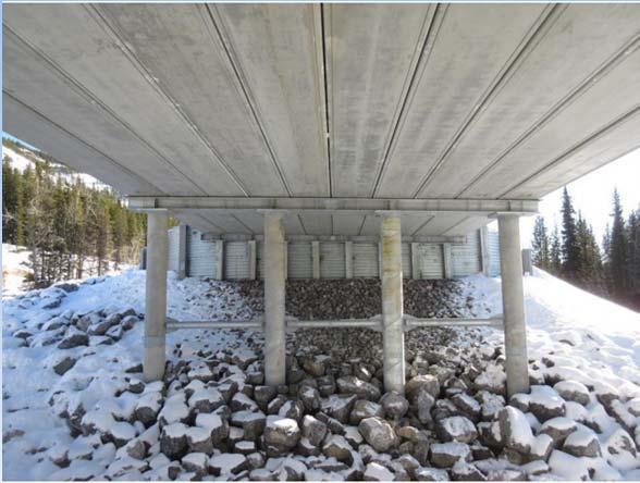
.") BRIDGE INSPECTION BRIDGE NO./NAME N4-005: Akolkolex Crawford FSR (19.0 km) Inspection Date: September 22 nd, 2012 Inspected By: M. Hanson, R. Veitch Year Built: 1982 Number of Spans: 1 Span Lengths: Superstructure
BRIDGE INSPECTION BRIDGE NO./NAME N4-005: Akolkolex Crawford FSR (19.0 km) Inspection Date: September 22 nd, 2012 Inspected By: M. Hanson, R. Veitch Year Built: 1982 Number of Spans: 1 Span Lengths: Superstructure
2011 BRIDGE INSPECTION REPORT
 2011 BRIDGE INSPECTION REPORT BYRD PARK PUMP STATION BRIDGE OVER KANAWHA CANAL April 2011 FINAL December 2011 Looking - from Abutment B to Abutment A Prepared by: WHITMAN, REQUARDT, & ASSOCIATES, LLP 9030
Executive Summary RPT-GEN November 28. Bridge No Quartz Creek Bridge Inspection Report
 Executive Summary The No. 01607 carries the Trans-Canada Highway over Quartz Creek, approximately 45 km northwest of Golden, BC. As part of an Enhanced Bridge Inspection Program, the BC Ministry of Transportation
VIRGINIA DEPARTMENT OF TRANSPORTATION NORTHERN VIRGINIA DISTRICT
 VIRGINIA DEPARTMENT OF TRANSPORTATION NORTHERN VIRGINIA DISTRICT STATE BRIDGE NO. 6081 CITY OR COUNTY 053 LOUDOUN TYPE OF BRIDGE REPORT: REGULAR INSPECTION JANUARY 2016 BRIDGE NAME: DIRECTION: FOREST MILLS
UNDERWATER BRIDGE INSPECTION REPORT STRUCTURE NO CSAH 24 OVER HAWKINSON CREEK ST. LOUIS COUNTY
 UNDERWATER BRIDGE INSPECTION REPORT STRUCTURE NO. 7685 CSAH 24 OVER HAWKINSON CREEK ST. LOUIS COUNTY JUNE 21, 2012 PREPARED FOR THE MINNESOTA DEPARTMENT OF TRANSPORTATION BY COLLINS ENGINEERS, INC. JOB
UNDERWATER BRIDGE INSPECTION REPORT STRUCTURE NO CRANE LAKE ROAD OVER HAWKINSON CREEK ST. LOUIS COUNTY
 UNDERWATER BRIDGE INSPECTION REPORT STRUCTURE NO. 7883 CRANE LAKE ROAD OVER HAWKINSON CREEK ST. LOUIS COUNTY JUNE 21, 2012 PREPARED FOR THE MINNESOTA DEPARTMENT OF TRANSPORTATION BY COLLINS ENGINEERS,
UNDERWATER BRIDGE INSPECTION REPORT STRUCTURE NO CSAH NO. 4 OVER THE CLEARWATER RIVER (DAM) DISTRICT 2 - CLEARWATER COUNTY
 DISTRICT 2 - CLEARWATER COUNTY") UNDERWATER BRIDGE INSPECTION REPORT STRUCTURE NO. 4992 CSAH NO. 4 OVER THE CLEARWATER RIVER (DAM) DISTRICT 2 - CLEARWATER COUNTY PREPARED FOR THE MINNESOTA DEPARTMENT OF TRANSPORTATION BY COLLINS ENGINEERS,
UNDERWATER BRIDGE INSPECTION REPORT STRUCTURE NO. 4992 CSAH NO. 4 OVER THE CLEARWATER RIVER (DAM) DISTRICT 2 - CLEARWATER COUNTY PREPARED FOR THE MINNESOTA DEPARTMENT OF TRANSPORTATION BY COLLINS ENGINEERS,
UNDERWATER BRIDGE INSPECTION REPORT STRUCTURE NO th STREET OVER THE ZUMBRO RIVER CITY OF ROCHESTER
 UNDERWATER BRIDGE INSPECTION REPORT STRUCTURE NO. 89188 7 th STREET OVER THE ZUMBRO RIVER CITY OF ROCHESTER OCTOBER 2, 2012 PREPARED FOR THE MINNESOTA DEPARTMENT OF TRANSPORTATION BY COLLINS ENGINEERS,
\\H\15\ PH9 Inspection Photos
 SHOP SLIDE Photo 1. at cracking across the footpath at the end of the Hwy 2 EB to Hwy 684 SB off ramp at the 99 Ave. intersection. Drop in asphalt trail (background) has worsened since 2013 and is now
STONY PLAIN REGION GEOHAZARD RISK ASSESSMENT SITE INSPECTION FORM HIGHWAY AND KM: Hwy 621:02, km 16.39
 SITE NUMBER AND NAME: NC 52 Pembina River Bridge LEGAL DESCRIPTION: SE 1-50-9-W5M STONY PLAIN REGION GEOHAZARD RISK ASSESSMENT SITE INSPECTION FORM HIGHWAY AND KM: Hwy 621:02, km 16.39 NAD 83 COORDINATES:
APPENDIX A INTEGRAL ABUTMENTS
 APPENDIX A INTEGRAL ABUTMENTS Appendix A Guidelines for Design of Integral Abutments Rev. 1 - September, 2007 These guidelines draw on the experiences and practices from Ontario, the FHWA, various DOT
Emergency Bridge Stabilization at Mile Watrous Subdivision
 Emergency Bridge Stabilization at Mile 189.70 Watrous Subdivision Christophe Deniaud, Ph.D., P.Eng. Bridge Engineer, CN 10004-104 Avenue Edmonton, Alberta, Canada T5J 0K2 Tel: (780) 421-6021 Fax: (780)
Questions and Answers on VDOT's Supplement to the AASHTO Manual for Bridge Element Inspection
 Questions and Answers on VDOT's Supplement to the AASHTO Manual for Bridge Element Inspection No. 1 2/26/2016 830 MSE Wall V 26 Is ADE 830 MSE Wall to be used in conjunction with NBE 218 Other Abutment
Using the sharp-crested weir formula the outflow was:
 Date: 2009 July 16 11:00 AM 14 Island Lake Dam Inspection Report Persons Present: Bryon Keene, P.Eng. Harry Stinson Brett Dark (14 Island Lake Association) Peter Peart (14 Island Lake Association) The
Reducing Bridge Damage Caused by Pavement Forces Part 1: Some Examples
 Reducing Bridge Damage Caused by Pavement Forces Part 1: Some Examples BY MARTIN P. BURKE, JR. Innumerable bridges both in the U.S. and abroad have been, and continue to be, damaged by the restrained growth
Three Bridges at I-64/Mercury Boulevard Interchange in Hampton, VA
 Three Bridges at I-64/Mercury Boulevard Interchange in Hampton, VA IRFAN A. ALVI, P.E., Alvi Associates, Inc., Baltimore, MD IBC-02-25 KEYWORDS: box girder, counterweight abutment, curved girder, high-performance
Appendix C Guidelines for Design of Integral Abutments March 3, 2003
 These guidelines draw on the experiences and practices from Ontario, the FHWA, various DOT s and the UK Highways Agency. They provide guidance and outline the issues that need to be considered and should
Integral Abutment Bridge Design with Soil Structure Interaction
 Integral Abutment Bridge Design with Soil Structure Interaction Thursday, May 11, 2017 3:00 PM 4:00 PM EST Speaker Engineer: Suthichai Saelim Project Location WESTBOROUGH Railroad HOPKINTON Project Location
Bank Erosion and Bridge Scour
 JULY 2017 NCHRP PRACTICE-READY SOLUTIONS FOR Bank Erosion and Bridge Scour NCHRP NATIONAL COOPERATIVE HIGHWAY RESEARCH PROGRAM RESEARCH TOPIC HIGHLIGHTS INTRODUCTION Bank Erosion and Bridge Scour: NCHRP
2017 UNDERWATER BRIDGE INSPECTION REPORT. TWP 332 over ROOT RIVER. Date of Inspection: Equipment Used: 10/22/2016. Town or Township Highway Agency
 2017 UNDERWATER BRIDGE INSPECTION REPORT BRIDGE # L4870 TWP 332 over ROOT RIVER DISTRICT: District 6 COUNTY: Fillmore CITY/TOWNSHIP: JORDAN STATE: Minnesota Date of Inspection: Equipment Used: 10/22/2016
Conditional assessment of Kiri Bridge in Shkoder, Albania
 Conditional assessment of Kiri Bridge in Shkoder, Albania Gentian Rexhaj 1, Enea Mustafaraj 2 1 2 Department of Civil Engineering, Epoka University, Albania 2 Department of Civil Engineering, Epoka University,
2016 UNDERWATER BRIDGE INSPECTION REPORT BRIDGE # CR
 2016 UNDERWATER BRIDGE INSPECTION REPORT BRIDGE # 88756 CR 597 over RICE RIVER DISTRICT: District 1 COUNTY: St. Louis CITY/TOWNSHIP: ANGORA STATE: Minnesota Date of Inspection: Equipment Used: 06/21/2016
Integral bridges and environmental conditions
 Integral bridges and environmental conditions COMISU CLAUDIU-CRISTIAN, BOACĂ GHEORGHITĂ Department of Roads and Foundations Faculty of Civil Engineering and Building Services The "Gheorghe Asachi" Technical
Inspection Report. River Falls Hydroelectric Project FERC Project No. P Junction Falls Dam River Falls, Wisconsin.
 Inspection Report River Falls Hydroelectric Project FERC Project No. P-10489 Junction Falls Dam River Falls, Wisconsin Prepared for: River Falls Municipal Utilities River Falls, Wisconsin December 2009
Numerical analysis of the embedded abutments of integral bridges
 Numerical analysis of the embedded abutments of integral bridges Ming XU Researcher, Dept. of Civil & Env. Engrg., University of Southampton, UK Summary Alan G. BLOODWORTH Lecturer, Dept. of Civil & Env.
SUMMARY OF NOVEMBER 2018 REVISIONS - VERSION
 SUMMARY OF NOVEMBER 2018 REVISIONS - VERSION 3.2.5.0 Since the release of BRADD Version 3.2.4.3, several operational issues have been addressed. This release of BRADD Version 3.2.5.0 contains the following
Technology. Reinforced Earth Wall Typical Section. Traffic Barrier. Roadway. Select Granular Material. Facing Panel Random Backfill.
 Bridge Applications Technology The Reinforced Earth Company (RECo) offers a variety of bridge abutment and bridge crossing solutions, each are based on project specific requirements. Bridge abutments are
ACCELERATED BRIDGE CONSTRUCTION PROJECT: THE REPLACEMENT OF MD 362 OVER MONIE CREEK
 ACCELERATED BRIDGE CONSTRUCTION PROJECT: THE REPLACEMENT OF MD 362 OVER MONIE CREEK Joseph Navarra, P.E, Maryland State Highway Administration, 410-545-8315, jnavarra@sha.state.md.us ABSTRACT The MDSHA
Flume Installation Instructions
 Flume Installation Instructions To ensure a successful installation, it is important to keep the following points in mind: 1) There should be no bend, dips, elbows, or flow junction immediately upstream
Rebuilding and widening the 54- year-old Jane Addams Memorial Tollway into a state-of-the-art corridor linking Rockford to Elgin (three lanes) and
 and") Overview Design criteria for I-90 over Kishwaukee Integral Abutment Bridges (IAB) Design Criteria Design analysis, details and construction Lessons Learned during construction Instrumentation by Illinois
Overview Design criteria for I-90 over Kishwaukee Integral Abutment Bridges (IAB) Design Criteria Design analysis, details and construction Lessons Learned during construction Instrumentation by Illinois
Filed: , EB , Exhibit B, Tab 1, Schedule 1, Attachment 3, Page 1 of 8
 Filed: 2018-07-04, EB-2018-0108, Exhibit B, Tab 1, Schedule 1, Attachment 3, Page 1 of 8 Stantec Consulting Ltd. 300-675 Cochrane Drive West Tower Markham ON L3R 0B8 Tel: (905) 944-7777 Fax: (905) 474-9889
research report Field Measurements on Skewed Semi-Integral Bridge With Elastic Inclusion: Instrumentation Report
 Final Report VTRC 06-R35 Virginia Transportation Research Council research report Field Measurements on Skewed Semi-Integral Bridge With Elastic Inclusion: Instrumentation Report http:/www.virginiadot.org/vtrc/main/online_reports/pdf/06-r35.pdf
PENNDOT e-notification
 PENNDOT e-notification Bureau of Design Engineering Computing Management Division BRADD No. 027 August 30, 2010 Release of Version 3.1.5.0 PennDOT's Bridge Automated Design and Drafting Software (BRADD)
SEPTEMBER, 2006 ROAD DESIGN MANUAL 7-0(1) CHAPTER 7 PAVEMENT DESIGN
 CHAPTER 7 PAVEMENT DESIGN") SEPTEMBER, 2006 ROAD DESIGN MANUAL 7-0(1) CHAPTER 7 PAVEMENT DESIGN 7-1.0 INTRODUCTION 7-2.0 RIGID PAVEMENT DESIGN 7-2.01 Cross Sections 7-2.02 Ramps and Loops with Storage Area 7-2.03 Major Forks, Branch
SEPTEMBER, 2006 ROAD DESIGN MANUAL 7-0(1) CHAPTER 7 PAVEMENT DESIGN 7-1.0 INTRODUCTION 7-2.0 RIGID PAVEMENT DESIGN 7-2.01 Cross Sections 7-2.02 Ramps and Loops with Storage Area 7-2.03 Major Forks, Branch
CHAPTER 5 MODELING OF THE BRIDGE
 62 CHAPTER 5 MODELING OF THE BRIDGE 5.1 MODELING SAP2000, a nonlinear software package was used for modeling and analysing the study bridge. The following list provides details about the element type used
Stantec Consulting Ltd Cochrane Drive West Tower Markham ON L3R 0B8 Tel: (905) Fax: (905)
 Fax: (905)") Filed: 2018-07-04, EB-2018-0108, Exhibit B, Tab 1, Schedule 1, Attachment 4, Page 1 of 10 Stantec Consulting Ltd. 300-675 Cochrane Drive West Tower Markham ON L3R 0B8 Tel: (905) 944-7777 Fax: (905) 474-9889
Filed: 2018-07-04, EB-2018-0108, Exhibit B, Tab 1, Schedule 1, Attachment 4, Page 1 of 10 Stantec Consulting Ltd. 300-675 Cochrane Drive West Tower Markham ON L3R 0B8 Tel: (905) 944-7777 Fax: (905) 474-9889
Shifting the Canning Bus Bridge Sideways
 Shifting the Canning Bus Bridge Sideways Ros MacKinlay Design Engineer, Wyche Consulting SYNOPSIS The Perth Mandurah railway proposed in 2002 required the replacement of an existing Kwinana Freeway bus
Semi-Integral Abutment Bridges
 Ministry of Transportation Report BO-99-03 Bridge Office Leslie Street Over Hwy 407 Semi-Integral Abutment Bridges Ministry of Transportation Report BO-99-03 Bridge Office Semi-Integral Abutment Bridges
OVER US 6 LATERAL BRIDGE SLIDE: I-75
 LATERAL BRIDGE SLIDE: I-75 OVER US 6 Bob Beasley, PE, Ohio Bridge Manager, Arcadis U.S., Inc. Todd Lezon, Regional Manager, Kokosing Construction Company, Inc. November 4, 2016 1 Agenda Design Bob Beasley,
Retrofit to improve earthquake performance of bridge abutment slopes
 Proceedings of the Ninth Pacific Conference on Earthquake Engineering Building an Earthquake-Resilient Society 14-16 April, 2011, Auckland, New Zealand Retrofit to improve earthquake performance of bridge
IL 115 OVER GAR CREEK ACCELERATED BRIDGE REPLACEMENT. Chad Hodel, S.E., P.E. (WHKS) Stan Kaderbek, S.E., P.E. (Milhouse)
 Stan Kaderbek, S.E., P.E. (Milhouse)") IL 115 OVER GAR CREEK ACCELERATED BRIDGE REPLACEMENT Chad Hodel, S.E., P.E. (WHKS) Stan Kaderbek, S.E., P.E. (Milhouse) AGENDA Project Overview and Need Design and Special Provisions Construction Engineering
IL 115 OVER GAR CREEK ACCELERATED BRIDGE REPLACEMENT Chad Hodel, S.E., P.E. (WHKS) Stan Kaderbek, S.E., P.E. (Milhouse) AGENDA Project Overview and Need Design and Special Provisions Construction Engineering
1 Study the drawings and the installation. 2 Ensure that you have the correct components. 3 Follow the manufacturer s instructions
 1 Study the drawings and the installation plan ahead of time. Consider laying the components out in the approximate order in which they will be installed. This will help workers become familiar with the
Webinar Q&A Documentation Slide In Bridge Construction (SIBC) Construction/Contractor Perspective March 6, 2014
 Construction/Contractor Perspective March 6, 2014") Updated: 5/15/14 1 What was driver for deciding to slide vs. roll? Overall weight? 2 1. Why the two different slide methods? 2. How much experience should your contractor have to perform the slide work?
Updated: 5/15/14 1 What was driver for deciding to slide vs. roll? Overall weight? 2 1. Why the two different slide methods? 2. How much experience should your contractor have to perform the slide work?
Potential For Fracture To Occur In Iowa DOT Steel Girder Bridges Due to Triaxial Constraint
 Potential For Fracture To Occur In Iowa DOT Steel Girder Bridges Due to Triaxial Constraint Introduction The purpose of this white paper is to provide information regarding the potential for fractures
EAH 422 ADVANCED WATER RESOURCES ENGINEERING
 EAH 422 ADVANCED WATER RESOURCES ENGINEERING Bridge Hydraulics Prof. Aminuddin Ab. Ghani References The Art And Science Of River Engineering Bridge Failure Pier scour Pier scour Pier scour Bridge Failure
Analyses of State Highway Bridges Damaged in the Darfield and Christchurch Earthquakes
 Analyses of State Highway Bridges Damaged in the Darfield and Christchurch Earthquakes J. H. Wood John Wood Consulting, Lower Hutt. ABSTRACT: 2012 NZSEE Conference Twelve State Highway (SH) bridges subjected
Modular Steel Bridges. Stark County Fischer Bridge Bottineau County Oak Creek Bridge
 Modular Steel Bridges Stark County Fischer Bridge Bottineau County Oak Creek Bridge This John Deere grain hauler was too heavy for the bridge. OOPS! An excavator and tow truck are needed to remove the
MONTANA FLUME. User s Manual. Montana (Short Parshall) Flume User s Manual
 Flume User s Manual") MONTANA FLUME User s Manual i Montana (Short Parshall) Flume User s Manual TABLE OF CONTENTS Introduction to the Montana Flume... 1 Function... 1 Design... 1 Standards... 2 Accuracy... 3 Dimensions...
MONTANA FLUME User s Manual i Montana (Short Parshall) Flume User s Manual TABLE OF CONTENTS Introduction to the Montana Flume... 1 Function... 1 Design... 1 Standards... 2 Accuracy... 3 Dimensions...
Keywords: integral abutment bridge, pile head abutment connection, finite element method.
 Global Journal of Researches in Engineering: e Civil And Structural Engineering Volume 15 Issue 1 Version 1.0 Year 2015 Type: Double Blind Peer Reviewed International Research Journal Publisher: Global
Appendix B. Shallow Foundations Report
 12/10/2013 GEOTECHNICAL MANUAL Appendix B. Shallow Foundations Report PLEASE NOTE A sample foundations report is included here for reference. It is provided as an example of content, format, and organization
5 DAMAGE TO TRANSPORTATION FACILITIES
 5 DAMAGE TO TRANSPORTATION FACILITIES In the Kocaeli, Turkey earthquake of August 17, 1999, extensive damage of transportation facilities occurred in the Kocaeli and Sakarya region, Turkey as shown in
A Tale of Two Bridges: Comparison between the Seismic Performance of Flexible and Rigid Abutments
 A Tale of Two Bridges: Comparison between the Seismic Performance of Flexible and Rigid Abutments A.M. Morsy. Department of Civil, Architectural, and Environmental Engineering, The University of Texas
The Structure upon which the ends of a Bridge rests is referred to as an Abutment
 ABUTMENTS The Structure upon which the ends of a Bridge rests is referred to as an Abutment The most common type of Abutment Structure is a Retaining Wall, Although other types of Abutments are also possible
PRELIMINARY GEOTECHNICAL DESIGN
 PNCC Manawatu River Pedestrian/ Cycle Bridge PRELIMINARY GEOTECHNICAL DESIGN 1 Introduction Opus has been commissioned by the Palmerston North City Council (PNCC) to prepare a Detailed Business Case (DBC)
Update on Seismic Behavior and Design of
 Update on Seismic Behavior and Design of Steel Plate Girder Bid Bridges Ahmad M. Itani, Ph.D., P.E., S.E. Professor Department of Civil and Environmental Engineering University of Nevada, Reno Background
Modified Sheet Pile Abutment for Low-Volume Road Bridge
 Modified Sheet Pile Abutment for Low-Volume Road Bridge Ryan R. Evans Department of Civil, Construction, and Environmental Engineering Iowa State University 176 Town Engineering Ames, IA 50011 ryevans@iastate.edu
Critically damaged bridges & concepts for earthquake recovery
 Critically damaged bridges & concepts for earthquake recovery J. Waldin, J. Jennings & P. Routledge Opus International Consultants Ltd, Christchurch, New Zealand 2012 NZSEE Conference ABSTRACT: This paper
Bridge Office Trunk Highway Bridge Flood Response Plan
 Bridge Office Trunk Highway Bridge Flood Response Plan Updated 7/18/2012 Purpose Bridges are vulnerable to damage and failure during flooding. Scour may undermine the bridge foundations or remove the protection
BEHAVIOR AND ANALYSIS OF AN INTEGRAL ABUTMENT BRIDGE
 BEHAVIOR AND ANALYSIS OF AN INTEGRAL ABUTMENT BRIDGE Paul J. Barr Marv W. Halling Conner Huffaker Hugh Boyle Utah State University Department of Civil and Environmental Engineering Logan, Utah September
MBW3-45 ELR: No coring surveys have been found for this structure. There are no records of any previous inspections of the structure.
 Scour Assessment Report Location Plan: Scale 1:5,000 MBW3-45 Score: 16.86 ELR: Contains Ordnance Survey data Crown copyright and database right 2010 Category: HIGH Assessment Date: 19/11/2010 Contract:
Aerial of Conceptual Path and Bridge Tysons-Old Meadow Road Bike/Ped Improvements
 Aerial of Conceptual Path and Bridge Barnes & Noble at One Place Project Location Corner Center Proposed Bridge Encore Condominiums Regency Club Condominiums Path continues to Dolley Madison Boulevard
Figure 3: Analytic procedure
 International Journal of Scientific and Research ublications, Volume 7, Issue 5, May 2017 567 Investigation of Integral Bridge Effect under Dynamic Loading Haymanmyintmaung *,kyawlinnhtat ** * Department
Geosynthetic Reinforced Soil (GRS) Integrated Bridge Systems (IBS) John Bowders University of Missouri
 Integrated Bridge Systems (IBS) John Bowders University of Missouri") Geosynthetic Reinforced Soil (GRS) Integrated Bridge Systems (IBS) John Bowders University of Missouri Adams et al. (2012), FHWA Geosynthetic Reinforced Soil Integrated Bridge System Interim Implementation
Geosynthetic Reinforced Soil (GRS) Integrated Bridge Systems (IBS) John Bowders University of Missouri Adams et al. (2012), FHWA Geosynthetic Reinforced Soil Integrated Bridge System Interim Implementation
DATA GATHERING AND DESIGN DETAILS OF AN INTEGRAL ABUTMENT BRIDGE
 DATA GATHERING AND DESIGN DETAILS OF AN INTEGRAL ABUTMENT BRIDGE Abstract S. Hassiotis M. ASCE Stevens Institute of Technology, Hoboken, N.J. 07030 sophia.hassiotis@stevens.edu An integral-abutment bridge
DESIGN AND CONSTRUCTION OF BR1449 VICTORIA PARK DRIVE MODIFICATIONS, BURSWOOD, WA
 DESIGN AND CONSTRUCTION OF BR1449 VICTORIA PARK DRIVE MODIFICATIONS, BURSWOOD, WA Brian Lord, Arup Pty Ltd, Australia ABSTRACT Arup was lead designer for Lend Lease on the Victoria Park Drive Modifications
Earthquake Resistance of Bridges With Friction Slab Abutments
 Earthquake Resistance of s With Friction Slab Abutments J. H. Wood John Wood Consulting, Lower Hutt. ABSTRACT: 2010 NZSEE Conference Findings from experimental and numerical research on the force resistance
Ashton Avenue Integral Bridge
 Ashton Avenue Integral Bridge Behzad Golfa, Senior Bridge Engineer, GHD Pty Ltd ABSTRACT The Ashton Avenue Bridge is a replacement of the original three-span timber bridge over Perth- Fremantle Rail line
Structural health monitoring of the reinforced concrete plug joint system for existing concrete bridges
 Proceedings of the 9th International Conference on Structural Dynamics, EURODYN 214 Porto, Portugal, 3 June - 2 July 214 A. Cunha, E. Caetano, P. Ribeiro, G. Müller (eds.) ISSN: 2311-92; ISBN: 978-972-752-165-4
Detailed Seismic Assessment and Seismic Improvements of Market Road Underpass
 Detailed Seismic Assessment and Seismic Improvements of Market Road Underpass D. Novakov, D. Ashby, T. Chin & A. George Opus International Consultants Ltd, Wellington - Auckland, New Zealand. G. Gregg
CHAPTER 11 APPENDIX D
 OFFICE OF STRUCTURES STRUCTURE HYDROLOGY AND HYDRAULICS DIVISION CHAPTER 11 APPENDIX D SCOUR COUNTERMEASURES FOR PIERS AND ABUTMENTS MAY 2015 Maryland SHA Office of Structures, Chapter 11, Appendix D May2015Page
s MASH Mobility (m/s)/n Frequency, Hz 2.5 x x x x x Average mobility
/n Frequency, Hz 2.5 x x x x x Average mobility") Purpose For a long time, users of NDT systems have wished for a rapid, easy to use method for rapid screening of the integrity of structures. The s MASH impulse-response test system fulfills this wish.
Purpose For a long time, users of NDT systems have wished for a rapid, easy to use method for rapid screening of the integrity of structures. The s MASH impulse-response test system fulfills this wish.
Geosynthetic-reinforced soil bridge abutments
 Geosynthetic-reinforced soil bridge abutments Measuring the performance of geosynthetic reinforcement in a Colorado bridge structure. By Jorge G. Zornberg, Naser Abu-Hejleh, and Trever Wang The technology
County of Orange. Presented to the Flood Division August 13, 2001 by Nadeem Majaj
 Using HECRAS TO Evaluate Scour At Bridges County of Orange Presented to the Flood Division August 3, 200 by Nadeem Majaj Approximately 575,000 bridges are built over waterways in the US. The most common
Bahavior and Analysis of an Integral Abutment Bridge
 Utah State University DigitalCommons@USU All Graduate Theses and Dissertations Graduate Studies 2013 Bahavior and Analysis of an Integral Abutment Bridge Conner D. Huffaker Follow this and additional works
AN EXPERIMENTAL INVESTIGATION ON BEHAVIOR OF RC PARAPET WALL OF ABUTMENT UNDER COLLISION
 International Journal of Civil Engineering and Technology (IJCIET) Volume 9, Issue 9, September 2018, pp. 1831 1838, Article ID: IJCIET_09_09_177 Available online at http://www.iaeme.com/ijciet/issues.asp?jtype=ijciet&vtype=9&itype=9
Draft. Not yet Approved. Natural Waterways 2012
 Natural Waterways 2012 3.1 General 1 3 5 3.1.1 Scope (2012) 1 3 5 3.1.2 Importance (1992) R(2012) 1 3 5 3.2 Hydrologic Capacity of Waterway Openings1 1 3 5 3.2.1 General (2012) 1 3 5 3.2.2 Drainage Basin
Fort Goff Creek Bridge R04 ABC Project. Dorie Mellon, PE Structure Policy & Innovation Division of Engineering Services Caltrans May 20, 2015
 Fort Goff Creek Bridge R04 ABC Project Dorie Mellon, PE Structure Policy & Innovation Division of Engineering Services Caltrans May 20, 2015 Fort Goff Creek Bridge Lead Adopter SHRP2 Solutions Innovative
SUMMARY OF NOVEMBER 2013 REVISIONS - VERSION
 SUMMARY OF NOVEMBER 2013 REVISIONS - VERSION 3.2.0.0 Since the release of BRADD Version 3.1.6.2, several major enhancements have been made to the software and many reported operational issues have been
Fun With Foam Deep Injection
 Fun With Foam Deep Injection Stephen Cruise Environmental Resource Specialist Where were we? Original Project Culvert to Bridge Fish Passage Improvement Modular Concrete Block bridge design Pacific Bridge
Independent Hybrid Corrosion Protection Appraisal
 Transportation Concrete Preservation Technologies Ltd 07/05/2015 Independent Hybrid Corrosion Protection Appraisal On behalf of: Concrete Preservation Technologies Ltd. Prepared by:... Checked by:... Wayne
Slip, Trip, and Fall Prevention Guide
 Slip, Trip, and Fall Prevention Guide Slips, trips and falls can happen in any workplace. They can occur at the entry of a building, in the kitchen, in cold rooms, on loading docks and even as you walk
Comparative Study of Behaviour of Integral and Bearing Type Bridge under Temperature Loading
 IJSRD - International Journal for Scientific Research & Development Vol. 3, Issue 03, 2015 ISSN (online): 2321-0613 Comparative Study of Behaviour of Integral and Bearing Type Bridge under ing B. J. Shah
EFFECTS OF SPATIAL VARIATION OF SEISMIC INPUTS ON BRIDGE LONGITUDINAL RESPONSE
 13 th World Conference on Earthquake Engineering Vancouver, B.C., Canada August 1-6, 24 Paper No. 64 EFFECTS OF SPATIAL VARIATION OF SEISMIC INPUTS ON BRIDGE LONGITUDINAL RESPONSE Jiachen WANG 1, Athol
EXAMINATION OF THE RESPONSE OF SKEWED STEEL BRIDGE SUPERSTRUCTURE DURING DECK PLACEMENT
 Norton et al. Word Count: 8400 Tables: 5 Figures: 13 1 EXAMINATION OF THE RESPONSE OF SKEWED STEEL BRIDGE SUPERSTRUCTURE DURING DECK PLACEMENT Date submitted: 08/01/02 Date Revised and Resubmitted: 11/15/02
Integral Abutment Bridges-Development of Soil Model for Soil Structure Interaction in Time History Analysis
 International Journal of Engineering Research and Development e-issn: 2278-067X, p-issn: 2278-800X, www.ijerd.com Volume 10, Issue 3 (March 2014), PP.31-40 Integral Abutment Bridges-Development of Soil
Ahmed Mongi, M.S., P.E. Engineering Division
 1 Ahmed Mongi, M.S., P.E. Engineering Division 2 Honey Creek Bridge Completed in 2006 at a cost of $2.6 Million Precast pier caps and abutments. 3 Honey Creek Bridge Bridge closed for 60 days Simple span
Development of Abutment Design Standards for Local Bridge Designs Volume 1 of 3
 F. W. Klaiber, D. J. White, T. J. Wipf, B. M. Phares, V. W. Robbins Development of Abutment Design Standards for Local Bridge Designs Volume 1 of 3 Development of Design Methodology August 2004 Sponsored
STATE ROUTE 30 OVER BESSEMER AVE. SUPERSTRUCTURE REPLACEMENT IN 57 HOURS
 STATE ROUTE 30 OVER BESSEMER AVE. SUPERSTRUCTURE REPLACEMENT IN 57 HOURS Louis J. Ruzzi P.E., PennDOT District 11-0 Bridge Engineer John Myler, PennDOT Assistant Construction Engineer, District 11-0 Bala
The short path seepage area is between the dam embankment and the bend in the existing drainage tunnel. This area is highlighted in red on the
 2 The short path seepage area is between the dam embankment and the bend in the existing drainage tunnel. This area is highlighted in red on the picture in the top left hand corner. Water in this pathway
Effect of Pile Orientation in Skewed Integral Abutment Bridges
 Effect of Pile Orientation in Skewed Integral Abutment Bridges RABIH NAJIB, Ph.D., PE, Alpha Corporation, Baltimore, Maryland and AMDE M. AMDE, Ph.D., PE, University of Maryland, College Park, Maryland
SEISMIC PERFORMANCE OF SEAT- TYPE ABUTMENT HIGHWAY BRIDGES IN ILLINOIS
 CIVIL ENGINEERING STUDIES Illinois Center for Transportation Series No. 18-015 UILU-ENG-2018-2015 ISSN: 0197-9191 SEISMIC PERFORMANCE OF SEAT- TYPE ABUTMENT HIGHWAY BRIDGES IN ILLINOIS Prepared By James
Bridge pile abutment deck interaction in laterally spreading ground: Lessons from Christchurch
 Bridge pile abutment deck interaction in laterally spreading ground: Lessons from Christchurch P.Tasiopoulou,E. Smyrou School of Civil Engineering, National Technical University, Athens İ.E. Bal Istanbul
Winona Bridge Visual Quality Review Committee
 Winona Bridge Visual Quality Review Committee Summary of Preferred Features October 7, 2014 Creating Bridges As Art 1 Summary of Preferred Features Based on Visual Quality Review Committee Final Design
STUDY OF THE REASONS THAT INDUCE CRACKS AT BRIDGE DECK END
 STUDY OF THE REASONS THAT INDUCE CRACKS AT BRIDGE DECK END by Zhengyu Liu Research Team: Zhengyu Liu, Graduate Research Student, Bridge Engineering Center, Iowa State University Brent M Phares, Director,
Product Information Packet
 Product Information Packet Pendulum Full Rack Product Part Number: 410706 Patents: #D562670, Patent Pending Pendulum Full Rack shown with optional pull-up arches. Table of Contents Introduction..... 1
ABSCOUR 9 USERS MANUAL
 OFFICE OF STRUCTURES BRIDGE SCOUR PROGRAM CHAPTER 11 APPENDIX A ABSCOUR 9 USERS MANUAL PART 1: DERIVATION OF METHODOLOGY APRIL 2011 Preface ABSCOUR 9, Build 2.3 is the current version of this program as
1 Exam Prep. SMACNA Architectural Sheet Metal Questions
 1 Exam Prep SMN rchitectural Sheet Metal Questions 1. Which of the following is not an advantage of terne? Lightweight High expansion rate Low expansion rate urable 2. ownspouts should be constructed with
Two-Dimensional Computer Modeling of Pomme de Terre River at Highways 12 and 22 in Minnesota
 Two-Dimensional Computer Modeling of Pomme de Terre River at Highways 12 and 22 in Minnesota Kamal Saffarinia 1, G. Kenneth Young 2, J. Sterling Jones 3, and Stuart Stein 4 This paper investigates two-dimensional