MatrixMIDFACE Plate and Screw System. Surgical Technique
|
|
|
- Sophia Knight
- 5 years ago
- Views:
Transcription


1 MatrixMIDFACE Plate and Screw System Surgical Technique
2 Image intensifier control This description alone does not provide sufficient background for direct use of DePuy Synthes products. Instruction by a surgeon experienced in handling these products is highly recommended. Processing, Reprocessing, Care and Maintenance For general guidelines, function control and dismantling of multi-part instruments, as well as processing guidelines for implants, please contact your local sales representative or refer to: For general information about reprocessing, care and maintenance of Synthes reusable devices, instrument trays and cases, as well as processing of Synthes non-sterile implants, please consult the Important Information leaflet (SE_023827) or refer to:
3 Table of Contents Introduction MatrixMIDFACE Plate and Screw System 2 AO Principles 6 Intended Use, Indications, Contraindications, 7 Warnings, Precautions, General Adverse Events and MRI Information Surgical Technique Trauma Repair and Reconstruction 10 Orbital Plates 16 Product Information MatrixMIDFACE Plates Orbital 21 MatrixMIDFACE Plates Standard 24 Instruments 31 MatrixMIDFACE Modules 35 Ordering Information 38 Surgical Technique MatrixMIDFACE DePuy Synthes 1


4 MatrixMIDFACE Plate and Screw System Introduction The aim of surgical fracture treatment is to reconstruct the bony anatomy and restore its function. According to the AO, internal fixation is distinguished by anatomical reduction, stable fixation, preservation of blood supply, and early, active mobilization. 1 Plate and screw osteosynthesis has been established and clinically recognized for some time. Keeping the AO philosophy at its core, Matrix is the new plating platform for internal fixation of the craniomaxillo- facial skeleton-addressing neuro, craniofacial, mandibular, and orthognathic surgery. Matrix is a simple yet comprehensive system that offers flexibility and ease of use. All screws work with all plates within each Matrix system One blade for all screws within each Matrix system Reduced plate/screw profile, where applicable Self-retaining screws/blades that minimize cam-out* Standardized instrumentation Color-coding by strength for easy identification Rounded edges on plates for less irritation to soft tissue, where applicable Reduced inventory for hospitals without compromising clinical solutions *Data on file at DePuy Synthes 1 Müller ME, Allgöwer M, Schneider R, Willenegger H. Manual of Internal Fixation. 3 rd, expanded and completely revised edition. Berlin, Heidelberg, New York: Springer DePuy Synthes MatrixMIDFACE Surgical Technique


5 One screwdriver blade works for all screws self-tapping emergency screw self-drilling One screw diameter works for all plates One system for all midface trauma anatomical regions Surgical Technique MatrixMIDFACE DePuy Synthes 1
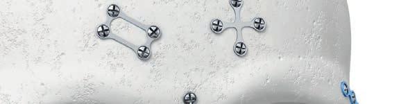
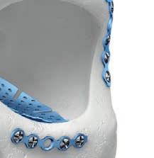
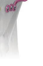
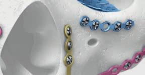
6 MatrixMIDFACE Plate and Screw System Micro plates, silver Anatomical Region: Nasal, orbital, and frontal region Midface plates 0.4 mm thick Orbital plates 0.2 mm thick Mini plates, blue Anatomical Region: Nasal, orbital, zygoma, frontal and maxillary region Midface plates 0.5 mm thick Orbital plates 0.3 mm thick 4 DePuy Synthes MatrixMIDFACE Surgical Technique
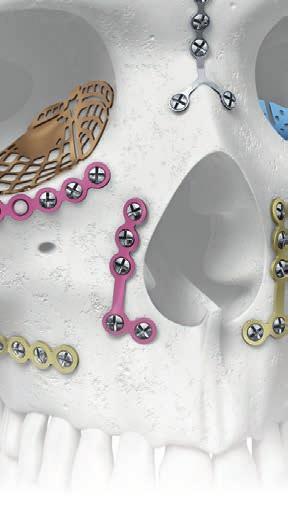
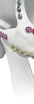
7 Medium plates, pink Anatomical Region: Nasal, orbital, zygoma, and maxillary region Midface plates 0.7 mm thick Orbital plates 0.4 mm thick Large plates, gold Anatomical Region: Central and lateral midface, orbital and zygoma region Midface plates 0.8 mm thick Orbital plates 0.5 mm thick MatrixMIDFACE plates color-coding/strength gradient Midface plates, thickness 0.4 mm 0.5 mm 0.7 mm 0.8 mm Orbital plates, thickness 0.2 mm 0.3 mm 0.4 mm 0.5 mm Surgical Technique MatrixMIDFACE DePuy Synthes 5
8 AO Principles In 1958, the AO formulated four basic principles, which have become the guidelines for internal fixation 1,2. They are: Anatomic reduction Fracture reduction and fixation to restore anatomical relationships. A comprehensive implant and instrument selection offers the ability to address most simple and complex fixation needs. Stable fixation Stability by rigid fixation or splintage, as the personality of the fracture and the injury requires. The MatrixMID- FACE Plate and Screw System is optimized to achieve stable bone fixation. Preservation of blood supply Preservation of the blood supply to soft tissue and bone by careful handling and gentle reduction techniques. Early, active mobilization Early and safe mobilization of the part and patient. The MatrixMIDFACE Plate and Screw System, combined with AO technique, provides stable fixation enough to allow a functional aftercare. 1 Müller ME, Allgöwer M, Schneider R, Willenegger H. Manual of Internal Fixation. 3 rd, expanded and completely revised edition. Berlin, Heidelberg, New York: Springer Rüedi TP, Buckley RE, Moran CG. AO Principles of Fracture Management. 2 nd expanded edition. Stuttgart, New York: Thieme DePuy Synthes MatrixMIDFACE Surgical Technique
9 Intended Use, Indications, Contraindications, Warnings, Precautions, General Adverse Events and MRI Information Intended Use MatrixMIDFACE Plate and Screw System is intended for use as trauma repair and reconstruction of the craniomaxillo facial skeleton. Indications MatrixMIDFACE Plate and Screw System is indicated for use in trauma repair and reconstruction of the craniomaxillofacial skeleton. MatrixMIDFACE Orbital Plates are indicated for orbital fracture treatment. MatrixMIDFACE Preformed Orbital Plates are indicated for use in: Orbital floor fractures Medial orbital wall fractures Combined orbital floor and medial wall fractures Contraindications No specific contraindications. Warnings: Using an internal fixation system on patients with active or latent infection may cause potential risks which may include construct failure and deterioration of infection. It is at the physician s discretion to evaluate the patient s medical conditions and select a fixation device most appropriate for the individual patient. It is also at the physician s discretion to consider all other necessary treatment methods to effectively manage the infection. Confirm the quality of bone at the selected plate position. Using an internal fixation system on patients with insufficient quantity or quality of bone may cause potential risks which may include device loosening and construct failure. It is at the physician s discretion to evaluate the patient s medical conditions and select a fixation device most appropriate for the individual patient. These devices can break during use (when subjected to excessive forces or outside the recommended surgical technique). While the surgeon must make the final decision on removal of the broken part based on associated risk in doing so, we recommend that whenever possible and practical for the individual patient, the broken part should be removed. Be aware that implants are not as strong as native bone. Implants subjected to substantial loads may fail. Instruments, screws and cut plates may have sharp edges or moving joints that may pinch or tear user s glove or skin. Take care to remove all fragments that are not fixated during the surgery. While the surgeon must make the final decision on implant removal, we recommend that whenever possible and practical for the individual patient, fixation devices should be removed once their service as an aid to healing is accomplished. Implant removal should be followed by adequate post-operative management to avoid refracture. Precautions: Confirm functionality of instruments and check for wear during reprocessing. Replace worn or damaged instruments prior to use. It is recommended to only use the instruments identified for use within the MatrixMIDFACE (DSEM/CMF/0216/0113) and MatrixORBITAL surgical techniques (DSEM/CMF/0216/0114) with the MatrixMIDFACE implants. Handle devices with care and dispose worn bone cutting instruments in a sharps container. Always irrigate and apply suction for removal of debris potentially generated during implantation or removal. General Adverse Events As with all major surgical procedures, risks, side effects and adverse events can occur. While many possible reactions may occur, some of the most common include: Problems resulting from anesthesia and patient positioning (e.g. nausea, vomiting, dental injuries, neurological impairments, etc.), thrombosis, embolism, infection, nerve and/or tooth root damage or injury of other critical structures including blood vessels, excessive bleeding, damage to soft tissues incl. swelling, abnormal scar formation, functional impairment of the musculoskeletal system, pain, discomfort or abnormal sensation due to the presence of the device, allergy or hypersensitivity reactions, side effects associated with hardware prominence, loosening, bending, or breakage of the device, mal-union, non-union or delayed union which may lead to breakage of the implant, reoperation. Surgical Technique MatrixMIDFACE DePuy Synthes 7
10 Intended Use, Indications, Contraindications, Warnings, Precautions, General Adverse Events and MRI Information Device-specific Adverse Events Device-specific adverse events include but are not limited to: Malunion / non-union that may be associated with: Implant inappropriately dimensioned for the intended use Hole deformation due to plate bending Construct failure due to inadequate strength design Construct strength too weak for post-operative loading forces Plate/mesh hole diameter too large or screw head too small Wrong implant material/design Misleading/incorrect label Information provided to the end-user (i.e. IFU, TG, care guide) is insufficient, incorrect or imprecise Insufficient screw holes left after plate has been cut Reverse and repeated bending applied Adverse Tissue Reaction that may be associated with: Instruments debris/particle created during cutting Instruments debris/particle created during implantation and/or removal Incorrect label i.e. wrong data provided on the LMD i.e. wrong text, missing symbols, wrong expiry date Damage to vital organs / surrounding structures that may be associated with: Premature plate/mesh failure Plate/mesh does not offer enough options for screw placement Plate/mesh too thick for anatomical area Fixation holes do not allow for appropriate fixation Insufficient mesh structure Screw placement into nerve, tooth buds/roots and or any other critical structures Screw core diameter is too small leading to screw breakage post-operatively Screw deforms or breaks during insertion with generation of fragments that the surgeon is unaware of or unable to retrieve, potentially resulting in fragment migration Screw recess strips due to blade cam-out Burrs/sharp edges on edge of plate Plate/mesh inadequately contoured resulting in inadequate reduction Screw breaks during insertion and fragments are not retrieved Screw breakage post-operatively Blade cams-out of screw recess Screw passes completely through plate Generation of particle debris during surgical procedure Screw strips bone post-operatively Screw not safely retained resulting in loss of screw intra-operatively Screw or plate migrates or deforms post-operatively Plate hole does not hold screw head Implant loses functionality post-operatively Improper use of implant resulting in treatment failure Wrong plate selection Incorrect plate/screw position resulting in irreversible damage Inappropriate use of screws or drill bits Overheating of drill bit causing thermal necrosis of bone Injury to user that may be associated with: Sharp edges caused during cutting of plates punctures surgical glove/hand Loosening that may be associated with: Insufficient implant fixation Screw breakage post-operatively Inappropriate screw used Peripheral Nerve that may be associated with: Screws inserted into nerve, tooth buds/roots and or any other critical structures Soft Tissue Damage that may be associated with: Premature plate/mesh failure Screw breakage post-operatively Burrs/sharp edges on edge of plate Implant loses its function post-operatively Systemic Infection that may be associated with: Incomplete/incorrect processing leading to implantation of a non-sterile product Sterile barrier compromised leading to implantation of a non-sterile product Implantation of non-sterile product Implantation of non-sterile unclean product due to incorrect label Reuse of single use implant 8 DePuy Synthes MatrixMIDFACE Surgical Technique
11 MRI Information Torque, Displacement and Image Artifacts according to ASTM F , ASTM F and ASTM F Non-clinical testing of a worst case scenario in a 3 T MRI system did not reveal any relevant torque or displacement of the construct for an experimentally measured local spatial gradient of the magnetic field of 5.4 T/m. The largest image artifact extended approximately 20 mm from the construct when scanned using the Gradient Echo (GE). Testing was conducted on a Siemens Prisma 3 T MRI system. Radio-Frequency-(RF-)induced heating according to ASTM F a Non-clinical electromagnetic and thermal simulations of a worst case scenario lead to temperature rises of 9.3 C (1.5 T) and 6 C (3 T) under MRI Conditions using RF Coils (whole body averaged specific absorption rate [SAR] of 2 W/kg for 15 minutes). Precautions: The above mentioned test relies on nonclinical testing. The actual temperature rise in the patient will depend on a variety of factors beyond the SAR and time of RF application. Thus, it is recommended to pay particular attention to the following points: It is recommended to thoroughly monitor patients undergoing MR scanning for perceived temperature and/or pain sensations. Patients with impaired thermoregulation or temperature sensation should be excluded from MR scanning procedures. Generally, it is recommended to use an MRI system with low field strength in the presence of conductive implants. The employed specific absorption rate (SAR) should be reduced as far as possible. Using the ventilation system may further contribute to reduce temperature increase in the body. Surgical Technique MatrixMIDFACE DePuy Synthes 9

12 Trauma Repair and Reconstruction 1. Expose and reduce fracture After completing the preoperative plan, expose the fracture or osteotomy site. In trauma reduce the fracture as required. Notes: For the reduction of displaced craniofacial fractures the MatrixMIDFACE Threaded Reduction Tools and T-Handle can be used. For handling instructions please refer to the MatrixMIDFACE Threaded Reduction Tools and T-Handle brochure ( ). 11 DePuy Synthes MatrixMIDFACE Surgical Technique
13 2. Select and prepare the implant Instruments Plate Holder, short Plate Holder, long Plate Cutter for MatrixMIDFACE top side bony side Select the appropriate plate for the nature of the fracture. Orient the plate so that the topside is facing out. Cut to length, if necessary. Optional Instruments Bending Templates for MatrixMIDFACE Note: When working with sterile implants, bending templates can be used to support the plate selection. Precautions: Bending templates are not intended to be implanted or used as a drill guide for surgical planning. In order to determine the appropriate amount of screws needed to achieve stable construct fixation, the surgeon should consider the fracture size and shape. Take care to protect soft tissue from trimmed plate edges. Surgical Technique MatrixMIDFACE DePuy Synthes 11
14 Trauma Repair and Reconstruction 3. Contour the plate Instruments Bending Pliers 3D for MatrixMIDFACE Plates Bending Pliers for MatrixMIDFACE Plates (two bending pliers required) Contour the plate to fit to the patient anatomy using the bending pliers. Ensure the plate is passively adapted to the bone. Precautions: If contouring is necessary, the surgeon should avoid bending the device at a screw hole. Avoid sharp bends, repetitive and reverse bending as it increases the risk of implant breakage. 4. Position the plate Instruments Plate Holder, short Plate Holder, long Place the plate over the fracture or osteotomy site. Precaution: Confirm that plate positioning allows for adequate clearance of nerves, tooth buds and/or tooth roots and any other critical structures. 11 DePuy Synthes MatrixMIDFACE Surgical Technique
15 5. Drill the hole Predrilling is recommended in complex fractures of the midface and in regions with thick cortical bone. Drill the first hole close to the fracture or osteotomy site. Notes: Screws are available in self-drilling (silver), self-tapping (bronze), and emergency (blue) designs. If a pilot hole is desired, use the appropriate 1.1 mm diameter MatrixMIDFACE drill bit for drilling up to 8 mm length and the 1.25 mm diameter MatrixMIDFACE drill bit for screw lengths of 10 mm or more. Precautions: Confirm that drill bit length and diameter correspond to selected screw length prior to drilling. Predrilling not recommended for 3 mm selfdrilling screws. Drill speed rate should never exceed 1,800 rpm, particularly in dense, hard bone. Higher drill speed rates can result in: thermal necrosis of the bone, soft tissue burns, an oversized hole, which can lead to reduced pull-out force, increased ease of the screws stripping in bone, suboptimal fixation, and/or the need for emergency screws. Always irrigate during drilling to avoid thermal damage to the bone and ensure drill bit is concentric to plate hole. Avoid damaging the plate threads with the drill. Avoid drilling over nerve or tooth roots. Take care while drilling as to not damage, entrap, or tear a patient s soft tissue or damage critical structures. Be sure to keep drill clear of loose surgical materials. Surgical Technique MatrixMIDFACE DePuy Synthes 11

16 Trauma Repair and Reconstruction 6. Screw insertion Instruments Screwdriver Shaft MatrixMIDFACE, short, self-holding, length 52 mm, with Hexagonal Coupling Screwdriver Shaft MatrixMIDFACE, medium, self-holding, length 76 mm, with Hexagonal Coupling Screwdriver Shaft MatrixMIDFACE, long, self-holding, length 96 mm, with Hexagonal Coupling Screwdriver Shaft MatrixMIDFACE, medium, with Holding Sleeve, length 79 mm, with Hexagonal Coupling Screwdriver Shaft MatrixMIDFACE, long, with Holding Sleeve, length 95 mm, with Hexagonal Coupling Handle, small, with Hexagonal Coupling Handle, medium, with Hexagonal Coupling Handle, large, with Hexagonal Coupling To engage the screw on the blade, align the blade over the cruciform recess and slowly rotate it counter-clockwise until the blade drops into the recess; firmly press the blade to fully seat it into the screw. A half counterclockwise rotation of the engaged screwdriver facilitates the screw removal from the clip. 11 DePuy Synthes MatrixMIDFACE Surgical Technique
17 Insert the first screw close to the fracture or osteotomy site, and tighten until secure. Insert the second screw on the opposite side of the fracture or osteotomy site, and then all remaining screws following the outlined procedure. If the screw is inserted with angulation, verify that the screw is safely retained in the plate hole and that the construct profile is not significantly increased. Precautions: Confirm screw length prior to implantation. In order to determine the appropriate amount of screws needed to achieve stable construct fixation, the surgeon should consider the fracture size and shape. Tighten screws in a controlled manner. Applying too much torque to the screws may cause screw/ plate deformation or bone stripping. If bone becomes stripped, remove the screw from the bone and replace with an emergency screw. Surgical Technique MatrixMIDFACE DePuy Synthes 11


18 Orbital Plates 1. Select plate design Instruments Plate Holder, short Plate Holder, long Select the appropriate plate shape and thickness that best suits the bony anatomy and treatment objective. Optional Instruments Bending Templates for MatrixMIDFACE Notes: When working with sterile implants bending templates can be used for the plate selection. For surgical technique for MatrixMIDFACE Preformed Orbital Plates including correct handling of the orbital retractors refer to the surgical technique DSEM/CMF/0216/ DePuy Synthes MatrixMIDFACE Surgical Technique
19 2. Adapt plate to the bone Instruments Cutting Scissor for Mesh Plates, short Cutting Scissor for Mesh Plates, long Bending Pliers 3D for MatrixMIDFACE Plates Bending Pliers for MatrixMIDFACE Plates (two bending pliers required) If required, cut and contour the plate to fit to the patient anatomy using the cutting scissor and the bending pliers respectively. Ensure that the plate is passively adapted to the bone. Precautions: Confirm that plate positioning allows for adequate clearance of nerves and any other critical structures. If contouring is necessary, the surgeon should avoid bending the device at a screw hole. Avoid sharp bends, repetitive and reverse bending as it increases the risk of implant breakage. The lateral anterior part of the MatrixMIDFACE Preformed Orbital Plate is intentionally prebent higher than the orbital rim anatomy to allow free plate movement during plate positioning. The lateral anterior part can be further contoured to match patient anatomy. Avoid contouring of the implant in situ that may lead to implant malposition and/or posterior cantilever effect. Take care to protect soft tissue from trimmed edges. Surgical Technique MatrixMIDFACE DePuy Synthes 11
20 Orbital Plates 3. Drill the hole Drill the hole with the appropriate diameter drill bit. Notes: Self-tapping and self-drilling screws are available. If a pilot hole is desired, use the appropriate 1.1 mm dia meter MatrixMIDFACE drill bit for drilling up to 8 mm length and the 1.25 mm diameter MatrixMIDFACE drill bit for screw lengths of 10 mm or more. Precautions: Confirm that drill bit length and diameter correspond to selected screw length prior to drilling. Predrilling not recommended for 3 mm selfdrilling screws. Drill speed rate should never exceed 1,800 rpm, particularly in dense, hard bone. Higher drill speed rates can result in: thermal necrosis of the bone, soft tissue burns, an oversized hole, which can lead to reduced pull-out force, increased ease of the screws stripping in bone, suboptimal fixation, and/or the need for emergency screws. Always irrigate during drilling to avoid thermal damage to the bone and ensure drill bit is concentric to plate hole. Avoid drilling over nerve or tooth roots. Take care while drilling as to not damage, entrap, or tear a patient s soft tissue or damage critical structures. Be sure to keep drill clear of loose surgical materials. 11 DePuy Synthes MatrixMIDFACE Surgical Technique

21 4. Fixate plate to the bone Instruments Screwdriver Shaft MatrixMIDFACE, short, self-holding, length 52 mm, with Hexagonal Coupling Screwdriver Shaft MatrixMIDFACE, medium, self-holding, length 76 mm, with Hexagonal Coupling Screwdriver Shaft MatrixMIDFACE, long, self-holding, length 96 mm, with Hexagonal Coupling Screwdriver Shaft MatrixMIDFACE, medium, with Holding Sleeve, length 79 mm, with Hexagonal Coupling Screwdriver Shaft MatrixMIDFACE, long, with Holding Sleeve, length 95 mm, with Hexagonal Coupling Handle, small, with Hexagonal Coupling Handle, medium, with Hexagonal Coupling Handle, large, with Hexagonal Coupling To engage the screw on the blade, align the blade over the cruciform recess and slowly rotate it counter-clockwise until the blade drops into the recess; firmly press the blade to fully seat it into the screw. A half counter - clockwise rotation of the engaged screwdriver facilitates the screw removal from the clip. Stabilize the implant with screws inserted through selected screw holes in the plate. Insert 1.5 mm Matrix- MIDFACE screws of appropriate length to secure the plate to the bone. If the screw is inserted with angulation, verify that the screw is safely retained in the plate hole and that the construct profile is not significantly increased. Surgical Technique MatrixMIDFACE DePuy Synthes 11
22 Orbital Plates Notes: Test for impingement: A forced duction test must be completed to ensure unrestricted lateral and medial movement of the globe. For the surgical technique for MatrixMIDFACE Preformed Orbital Plates refer to the surgical technique DSEM/CMF/0216/0114. Precautions: Confirm screw length prior to implantation. Tighten screws in a controlled manner. Applying too much torque to the screws may cause screw/ plate deformation or bone stripping. If bone becomes stripped, remove the screw from the bone and replace with an emergency screw. In order to determine the appropriate amount of screws needed to achieve stable construct fixation, the surgeon should consider the fracture size and shape. 22 DePuy Synthes MatrixMIDFACE Surgical Technique


23 MatrixMIDFACE Plates Orbital Orbital Floor Mesh Plate, thickness 0.2 mm, Pure Titanium Orbital Floor Mesh Plate, thickness 0.3 mm, Pure Titanium Anatomic Orbital Floor Plate, small, thickness 0.3 mm, Pure Titanium Anatomic Orbital Floor Plate, medium, thickness 0.3 mm, Pure Titanium Shown in actual size Surgical Technique MatrixMIDFACE DePuy Synthes 22


24 MatrixMIDFACE Plates Orbital Anatomic Orbital Floor Plate, large, thickness 0.3 mm, Pure Titanium Universal Orbital Floor Plate, thickness 0.4 mm, Pure Titanium Orbital Floor Mesh Plate, thickness 0.4 mm, Pure Titanium Shown in actual size 22 DePuy Synthes MatrixMIDFACE Surgical Technique


25 Universal Orbital Plate, thickness 0.5 mm, Pure Titanium / MatrixMIDFACE Preformed Orbital Plate, small, left/right, Pure Titanium / MatrixMIDFACE Preformed Orbital Plate, large, left/right, Pure Titanium Shown in actual size Surgical Technique MatrixMIDFACE DePuy Synthes 22


26 MatrixMIDFACE Plates Standard Micro Plates Orbital Rim Plate, 12 holes, thickness 0.4 mm, Pure Titanium MatrixMIDFACE Adaption Plate, 6 holes, thickness 0.4 mm, Pure Titanium MatrixMIDFACE Adaption Plate, 8 holes, thickness 0.4 mm, Pure Titanium Adaption Plate, 20 holes, thickness 0.4 mm, Pure Titanium Y-Plate, 3 holes, thickness 0.4 mm, Pure Titanium Double-Y-Plate, 6 holes, thickness 0.4 mm, Pure Titanium Frame Plate, 4 holes, 5 10 mm, thickness 0.4 mm, Pure Titanium Frame Plate, 4 holes, mm, thickness 0.4 mm, Pure Titanium X-Plate, 4 holes, thickness 0.4 mm, Pure Titanium Strut Plate, 18 holes, thickness 0.4 mm, Pure Titanium Shown in actual size 22 DePuy Synthes MatrixMIDFACE Surgical Technique
27 Mini Plates H-Plate, 11 holes, thickness 0.5 mm, Pure Titanium L-Plate, 2+3 holes, left, thickness 0.5 mm, Pure Titanium L-Plate, 2+3 holes, right, thickness 0.5 mm, Pure Titanium L-Plate, 3+4 holes, left, thickness 0.5 mm, Pure Titanium L-Plate, 3+4 holes, right, thickness 0.5 mm, Pure Titanium T-Plate, 3+4 holes, thickness 0.5 mm, Pure Titanium L-Plate, 4+6 holes, left, thickness 0.5 mm, Pure Titanium L-Plate, 4+6 holes, right, thickness 0.5 mm, Pure Titanium Orbital Rim Plate,12 holes, thickness 0.5 mm, Pure Titanium Shown in actual size Surgical Technique MatrixMIDFACE DePuy Synthes 22

28 MatrixMIDFACE Plates Standard Mini Plates Adaption Plate, 6 holes, thickness 0.5 mm, Pure Titanium Adaption Plate, 8 holes, thickness 0.5 mm, Pure Titanium Adaption Plate, 20 holes, thickness 0.5 mm, Pure Titanium Y-Plate, 3 holes, thickness 0.5 mm, Pure Titanium Double-Y-Plate, 6 holes, thickness 0.5 mm, Pure Titanium Frame Plate, 4 holes, 5 10 mm, thickness 0.5 mm, Pure Titanium Frame Plate, 4 holes, mm, thickness 0.5 mm, Pure Titanium X-Plate, 4 holes, thickness 0.5 mm, Pure Titanium Strut Plate, 18 holes, thickness 0.5 mm, Pure Titanium Shown in actual size 22 DePuy Synthes MatrixMIDFACE Surgical Technique


29 Medium Plates H-Plate, 11 holes, thickness 0.7 mm, Pure Titanium L-Plate, 2+3 holes, left, thickness 0.7 mm, Pure Titanium L-Plate, 2+3 holes, right, thickness 0.7 mm, Pure Titanium L-Plate, 3+4 holes, left, thickness 0.7 mm, Pure Titanium L-Plate, 3+4 holes, right, thickness 0.7 mm, Pure Titanium T-Plate, 3+4 holes, thickness 0.7 mm, Pure Titanium L-Plate, 4+6 holes, left, thickness 0.7 mm, Pure Titanium L-Plate, 4+6 holes, right, thickness 0.7 mm, Pure Titanium Orbital Rim Plate, 12 holes, thickness 0.7 mm, Pure Titanium Shown in actual size Surgical Technique MatrixMIDFACE DePuy Synthes 22


30 MatrixMIDFACE Plates Standard Medium Plates Adaption Plate, 6 holes, thickness 0.7 mm, Pure Titanium Adaption Plate, 8 holes, thickness 0.7 mm, Pure Titanium Adaption Plate, 20 holes, thickness 0.7 mm, Pure Titanium Y-Plate, 3 holes, thickness 0.7 mm, Pure Titanium Double-Y-Plate, 6 holes, thickness 0.7 mm, Pure Titanium Frame Plate, 4 holes, 5 10 mm, thickness 0.7 mm, Pure Titanium Frame Plate, 4 holes, mm, thickness 0.7 mm, Pure Titanium X-Plate, 4 holes, thickness 0.7 mm, Pure Titanium Strut Plate, 18 holes, thickness 0.7 mm, Pure Titanium Shown in actual size 22 DePuy Synthes MatrixMIDFACE Surgical Technique
31 Large Plates H-Plate, 11 holes, thickness 0.8 mm, Pure Titanium L-Plate, 2+3 holes, left, thickness 0.8 mm, Pure Titanium L-Plate, 2+3 holes, right, thickness 0.8 mm, Pure Titanium L-Plate, 3+4 holes, left, thickness 0.8 mm, Pure Titanium L-Plate, 3+4 holes, right, thickness 0.8 mm, Pure Titanium T-Plate, 3+4 holes, thickness 0.8 mm, Pure Titanium L-Plate, 4+6 holes, left, thickness 0.8 mm, Pure Titanium L-Plate, 4+6 holes, right, thickness 0.8 mm, Pure Titanium Adaption Plate, 20 holes, thickness 0.8 mm, Pure Titanium Shown in actual size Surgical Technique MatrixMIDFACE DePuy Synthes 22
32 MatrixMIDFACE Plates Standard Orbital Rim Plate, 12 holes, thickness 0.8 mm, Pure Titanium Adaption Plate, 6 holes, thickness 0.8 mm, Pure Titanium Adaption Plate, 8 holes, thickness 0.8 mm, Pure Titanium Shown in actual size 33 DePuy Synthes MatrixMIDFACE Surgical Technique


33 Instruments Plate Holders Short Long Handles, with Hexagonal Coupling Small Medium Large Screwdriver Shaft MatrixMIDFACE, self-holding, with Hexagonal Coupling Short, length 52 mm Medium, length 76 mm Long, length 96 mm Screwdriver Shaft MatrixMIDFACE, with Holding Sleeve, with Hexagonal Coupling Medium, length 79 mm Long, length 95 mm Surgical Technique MatrixMIDFACE DePuy Synthes 33
34 Instruments Bending Pliers 3D for MatrixMIDFACE Plates 33 DePuy Synthes MatrixMIDFACE Surgical Technique

35 Cutting Scissors for Mesh Plates, short Cutting Scissors for Mesh Plates, long Bending Pliers for MatrixMIDFACE Plates Plate Cutter for MatrixMIDFACE Surgical Technique MatrixMIDFACE DePuy Synthes 33


36 Instruments Orbital Retractor, left Orbital Retractor, right T-Handle, small, with Hexagonal Coupling Threaded Reduction Tools, hex coupling S Threaded Reduction Tool B 2.4 mm, self-drilling, length 78 mm, with Hexagonal Coupling, sterile Threaded Reduction Tool B 3.5 mm, self-tapping, length 78 mm, with Hexagonal Coupling Threaded Reduction Tool B 3.5 mm, self-tapping, length 43 mm, with Hexagonal Coupling 33 DePuy Synthes MatrixMIDFACE Surgical Technique


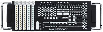
37 MatrixMIDFACE Modules MatrixMIDFACE Standard Set Configuration Module for MatrixMIDFACE Plates, 3/3, with Lid, without Contents Module for MatrixMIDFACE Screws and Instruments, 2/3, with Lid, without Contents Instrument Tray MatrixMIDFACE, 2/3, with Lid, without Contents Module for MatrixMIDFACE Plates, 3/3, with Lid, without Contents MatrixMIDFACE Plate Set, 3/ Module for MatrixMIDFACE Plates, blue 0.5 mm and pink 0.7 mm, 2/3, with Lid, without Contents MatrixMIDFACE Plate Set, blue 0.5 mm and pink 0.7 mm, 2/ Module for MatrixMIDFACE Plates, pink 0.7 mm and gold 0.8 mm, 2/3, with Lid, without Contents MatrixMIDFACE Plate Set, pink 0.7 mm and gold 0.8 mm, 2/3 Surgical Technique MatrixMIDFACE DePuy Synthes 33


38 MatrixMIDFACE Modules Module for MatrixMIDFACE Plates, blue 0.5 mm and gold 0.8 mm, 2/3, with Lid, without Contents MatrixMIDFACE Plate Set, blue 0.5 mm and gold 0.8 mm, 2/ Module for MatrixMIDFACE Plates, silver 0.4 mm and blue 0.5 mm, 2/3, with Lid, without Contents MatrixMIDFACE Plate Set, silver 0.4 mm and blue 0.5 mm, 2/ Module for MatrixMIDFACE Plates, silver 0.4 mm and pink 0.7 mm, 2/3, with Lid, without Contents MatrixMIDFACE Plate Set, silver 0.4 mm and pink 0.7 mm, 2/ Module for MatrixMIDFACE Screws and Instruments, 2/3, with Lid, without Contents MatrixMIDFACE Screws and Instrument Set, 2/ Module MatrixMIDFACE, 1/3, with Lid, without Contents, for use with sterile Implants MatrixMIDFACE Set, 1/3, for use with sterile Implants 33 DePuy Synthes MatrixMIDFACE Surgical Technique


 Surgical Technique MatrixORBITAL. MatrixMIDFACE Preformed Orbital Plates.")
39 This publication is not intended for distribution in the USA. Instruments and implants approved by the AO Foundation. CMF Matrix This publication is not intended for distribution in the USA. Instruments and implants approved by the AO Foundation Instrument Tray MatrixMIDFACE, 2/3, with Lid, without Contents MatrixMIDFACE Instrument Set, 2/ Instrument Tray for MatrixMIDFACE Threaded Reduction Tools and T-Handle, 1/3, with Lid, without Contents MatrixMIDFACE Threaded Reduction Tool and T-Handle Set, 1/ Module MatrixMIDFACE Compact, 3/3, with Lid, without Contents MatrixMIDFACE Compact Set, 3/3 Also available MatrixORBITAL Surgical Technique (DSEM/CMF/0216/0114) Surgical Technique MatrixORBITAL. MatrixMIDFACE Preformed Orbital Plates. Surgical Technique MatrixMIDFACE Threaded Reduction Tools and T-Handle. For the reduction of displaced craniofacial fractures. MatrixMIDFACE Threaded Reduction Tools and T-Handle Surgical Technique (DSEM/CMF/0916/0154) CMF Matrix Surgical Technique MatrixMIDFACE DePuy Synthes 33
40 Ordering Information MatrixMIDFACE Modules Module MatrixMIDFACE, 1/3, with Lid, without Contents, for use with sterile Implants Instrument Tray MatrixMIDFACE, 2/3, with Lid, without Contents Module for MatrixMIDFACE Plates, silver 0.4 mm and blue 0.5 mm, 2/3, with Lid, without Contents Module for MatrixMIDFACE Screws and Instruments, 2/3, with Lid, without Contents Module for MatrixMIDFACE Plates, silver 0.4 mm and pink 0.7 mm, 2/3, with Lid, without Contents, 2/ Module for MatrixMIDFACE Plates, 3/3, with Lid, without Contents Module for MatrixMIDFACE Plates, blue 0.5 mm and pink 0.7 mm, 2/3, with Lid, without Contents Module for MatrixMIDFACE Plates, blue 0.5 mm and gold 0.8 mm, 2/3, with Lid, without Contents Module for MatrixMIDFACE Plates, pink 0.7 mm and gold 0.8 mm, 2/3, with Lid, without Contents Module MatrixMIDFACE Compact, 3/3, with Lid, without Contents MatrixMIDFACE Screws, Titanium Alloy (TAN) Predrilling is recommended with 1.1 mm MatrixMIDFACE Drill Bits for screw lengths 3 mm 8 mm and 1.25 mm MatrixMIDFACE Drill Bits for screw lengths of 10 mm or more. Drill bits are combined with power tools Length 3 mm Length 4 mm Length 5 mm Length 6 mm Length 8 mm Length 10 mm Length 12 mm Length 14 mm Length 16 mm Length 18 mm Self-tapping Screws B 1.5 mm Self-drilling Screws B 1.5 mm Length 3 mm ( predrilling not recommended) Length 4 mm Length 5 mm Length 6 mm Length 8 mm Length 3 mm Length 4 mm Length 5 mm Length 6 mm Length 8 mm Length 10 mm Length 12 mm Length 14 mm Length 16 mm Length 18 mm Emergency Screws B 1.8 mm, self-tapping MatrixMIDFACE Plates, Pure Titanium Orbital Floor Plates Anatomic Orbital Floor Plate, small, thickness 0.3 mm Anatomic Orbital Floor Plate, medium, thickness 0.3 mm Anatomic Orbital Floor Plate, large, thickness 0.3 mm Universal Orbital Floor Plate, thickness 0.4 mm Universal Orbital Plate, thickness 0.5 mm Orbital Floor Mesh Plate, thickness 0.2 mm Orbital Floor Mesh Plate, thickness 0.3 mm Orbital Floor Mesh Plate, thickness 0.4 mm Preformed Orbital Plates Small, left Large, left Small, right Large, right Orbital Rim Plates holes, thickness 0.4 mm holes, thickness 0.5 mm holes, thickness 0.7 mm holes, thickness 0.8 mm Adaption Plates holes, thickness 0.4 mm holes, thickness 0.5 mm holes, thickness 0.7 mm holes, thickness 0.8 mm holes, thickness 0.4 mm holes, thickness 0.5 mm holes, thickness 0.7 mm holes, thickness 0.8 mm holes, thickness 0.4 mm holes, thickness 0.5 mm holes, thickness 0.7 mm holes, thickness 0.8 mm Y-Plates Y-Plate, 3 holes, thickness 0.4 mm Y-Plate, 3 holes, thickness 0.5 mm Y-Plate, 3 holes, thickness 0.7 mm Double-Y-Plate, 6 holes, thickness 0.4 mm Double-Y-Plate, 6 holes, thickness 0.5 mm Double-Y-Plate, 6 holes, thickness 0.7 mm 33 DePuy Synthes MatrixMIDFACE Surgical Technique
41 Frame Plates holes, 5 10 mm, thickness 0.4 mm holes, 5 10 mm, thickness 0.5 mm holes, 5 10 mm, thickness 0.7 mm holes, mm, thickness 0.4 mm holes, mm, thickness 0.5 mm holes, mm, thickness 0.7 mm X-Plates holes, thickness 0.4 mm holes, thickness 0.5 mm holes, thickness 0.7 mm Strut Plates holes, thickness 0.4 mm holes, thickness 0.5 mm holes, thickness 0.7 mm L-Plates holes, left, thickness 0.5 mm holes, left, thickness 0.7 mm holes, left, thickness 0.8 mm holes, right, thickness 0.5 mm holes, right, thickness 0.7 mm holes, right, thickness 0.8 mm holes, left, thickness 0.5 mm holes, left, thickness 0.7 mm holes, left, thickness 0.8 mm holes, right, thickness 0.5 mm holes, right, thickness 0.7 mm holes, right, thickness 0.8 mm holes, left, thickness 0.5 mm holes, left, thickness 0.7 mm holes, left, thickness 0.8 mm holes, right, thickness 0.5 mm holes, right, thickness 0.7 mm holes, right, thickness 0.8 mm T-Plates holes, thickness 0.5 mm holes, thickness 0.7 mm holes, thickness 0.8 mm H-Plates holes, thickness 0.5 mm holes, thickness 0.7 mm holes, thickness 0.8 mm Screw /plate overview Pack of 1 unit Pack of 4 units Pack of 1 unit, sterile Pack of 4 units, sterile Labelling clips Self-tapping screws (in clips) xxx.01C xxx.04C xxx.01S xxx.04S xxxLC Self-drilling screws (in clips) xxx.01C xxx xxx.01S xxx.04S xxxLC2 Emergency screws (in clips) xxx.01C xxx.01S xxxLC Plates xxx xxxS xxxLC Drill bits xxx xxxS xxxLC 1 For color-coding of MatrixMIDFACE plates refer to strength gradient on page 5. 2 Labelling clips for self-drilling screws are marked with SD , and self-tapping screws are only available in packs of 1 unit. Surgical Technique MatrixMIDFACE DePuy Synthes 33
42 Ordering Information Instruments Plate Holder, short Cutting Scissors for Mesh Plates, short Plate Holder, long Bending Pliers 3D for MatrixMIDFACE Plates Cutting Scissors for Mesh Plates, long Bending Pliers for MatrixMIDFACE Plates Plate Cutter for MatrixMIDFACE Screwdriver Shaft MatrixMIDFACE, self-holding, with Hexagonal Coupling Short, length 52 mm Medium, length 76 mm Long, length 96 mm Screwdriver Shaft MatrixMIDFACE, with Holding Sleeve, with Hexagonal Coupling Medium, length 79 mm Long, length 95 mm MatrixMIDFACE Drill Bits B 1.1 mm, for J-Latch Coupling Drill Bit with Stop, length 44.5/4 mm Drill Bit with Stop, length 44.5/6 mm Drill Bit with Stop, length 44.5/8 mm MatrixMIDFACE Drill Bits B 1.25 mm, for J-Latch Coupling Drill Bit with Stop, length 10/44.5 mm, 2-flute Drill Bit with Stop, length 12/44.5 mm, 2-flute Drill Bit with Stop, length 18/44.5 mm, 2-flute Drill Bit with Stop, length 18/125 mm, 2-flute Drill Bit, length 80 mm, 2-flute Drill Bit, length 125 mm, 2-flute MatrixMIDFACE Drill Bits B 1.1mm, for Mini Quick Coupling Drill Bit with Stop, length 44.5/4 mm Drill Bit with Stop, length 44.5/6 mm Drill Bit with Stop, length 44.5/8 mm MatrixMIDFACE Drill Bits B 1.25 mm, for Mini Quick Coupling Drill Bit with Stop, length 10/44.5 mm, 2-flute Drill Bit with Stop, length 12/44.5 mm, 2-flute Drill Bit with Stop, length 18/44.5 mm, 2-flute Drill Bit with Stop, length 18/125 mm, 2-flute Drill Bit, length 80 mm, 2-flute Drill Bit, length 125 mm, 2-flute Small Medium Large Handles, with Hexagonal Coupling MatrixMIDFACE Bending Templates Anatomic Orbital Floor Plate, small Anatomic Orbital Floor Plate, medium Anatomic Orbital Floor Plate, large Universal Orbital Floor Plate Universal Orbital Plate Orbital Floor Mesh Plate Adaption Plate, 20 holes Orbital Rim Plate, 12 holes L-Plate, 2+3 holes L-Plate, 3+4 holes L-Plate, 4+6 holes Y-Plate, 3 holes X-Plate, 4 holes H-Plate, 11 holes T-Plate, 3+4 holes Frame Plate, 4 holes, 5 10 mm Frame Plate, 4 holes, mm Strut Plate, 18 holes Double-Y-Plate, 6 holes, thickness 0.4 mm Double-Y-Plate, 6 holes, thickness 0.5 mm Double-Y-Plate, 6 holes, thickness 0.7 mm Additionally Available MatrixMIDFACE Orbital Retractors Orbital Retractor, left Orbital Retractor, right MatrixMIDFACE Threaded Reduction Tools and T-Handle Module Instrument Tray for MatrixMIDFACE Threaded Reduction Tools and T-Handle, 1/3, with Lid, without Contents Instruments T-Handle, small, with Hexagonal Coupling S Threaded Reduction Tool B 2.4 mm, self-drilling, length 78 mm, with Hexagonal Coupling, sterile Threaded Reduction Tool B 3.5 mm, self-tapping, length 78 mm, with Hexagonal Coupling Threaded Reduction Tool B 3.5 mm, self-tapping, length 43 mm, with Hexagonal Coupling Drill Guide Drill Bit B 2.4 mm, length 80 mm, 2-flute, for J-Latch Coupling Additionally Available Drill Bit B 1.8 mm, length 80 mm, 2-flute, for J-Latch Coupling Double Drill Guide 2.4/ DePuy Synthes MatrixMIDFACE Surgical Technique
43
44 DSEM/CMF/0216/0113(1) 02/18 Synthes GmbH Eimattstrasse Oberdorf Switzerland Tel: Fax: Not all products are currently available in all markets. This publication is not intended for distribution in the USA. All surgical techniques are available as PDF files at DePuy Synthes CMF, a division of Synthes GmbH All rights reserved
Compact Midface. The systematic solution for craniomaxillofacial indications and displacement osteotomies.
 Compact Midface. The systematic solution for craniomaxillofacial indications and displacement osteotomies. Surgical Technique This publication is not intended for distribution in the USA. Instruments and
LOW PROFILE NEURO. This publication is not intended for distribution in the USA. SURGICAL TECHNIQUE
 LOW PROFILE NEURO This publication is not intended for distribution in the USA. SURGICAL TECHNIQUE TABLE OF CONTENTS INTRODUCTION Low Profile Neuro Plating System 2 Intended Use, Indications, Contraindications
MatrixNEURO. The next generation cranial plating system.
 MatrixNEURO. The next generation cranial plating system. Surgical Technique This publication is not intended for distribution in the USA. Instruments and implants approved by the AO Foundation. Image intensifier
MatrixNEURO. The next generation cranial plating system.
 MatrixNEURO. The next generation cranial plating system. Technique Guide CMF Matrix This publication is not intended for distribution in the USA. Instruments and implants approved by the AO Foundation
Low Profile Neuro Plating System. Surgical Technique
 Low Profile Neuro Plating System Surgical Technique TABLE OF CONTENTS INTRODUCTION Low Profile Neuro Plating System 2 SURGICAL TECHNIQUE Technique 5 PRODUCT INFORMATION Low Profile Neuro Plates 10 Low
Compact 2.0 LOCK Mandible. The locking system for the mandible.
 Compact 2.0 LOCK Mandible. The locking system for the mandible. Surgical Technique This publication is not intended for distribution in the USA. Instruments and implants approved by the AO Foundation.
Orthodontic Bone Anchor (OBA) System
 System") Skeletal implants for the orthodontic movement of the teeth Orthodontic Bone Anchor (OBA) System Surgical Technique Image intensifier control This description alone does not provide sufficient background
Skeletal implants for the orthodontic movement of the teeth Orthodontic Bone Anchor (OBA) System Surgical Technique Image intensifier control This description alone does not provide sufficient background
MatrixMIDFACE Preformed Orbital Plates. MatrixORBITAL. Surgical Technique
 MatrixMIDFACE Preformed Orbital Plates MatrixORBITAL Surgical Technique Image intensifier control This description alone does not provide sufficient background for direct use of DePuy Synthes products.
low ProfIle neuro PlaTIng system
 low ProfIle neuro PlaTIng system surgical TeChnIque Table of Contents Introduction Low Profile Neuro Cranial Plating System 2 Surgical Technique Technique 5 Product Information Low Profile Neuro Plates
LCP Metaphyseal Plates. For extra-articular fractures.
 LCP Metaphyseal Plates. For extra-articular fractures. Surgical Technique This publication is not intended for distribution in the USA. Instruments and implants approved by the AO Foundation. Image intensifier
Technique Guide. Compact 2.0 LOCK Mandible. The locking system for the mandible.
 Technique Guide Compact 2.0 LOCK Mandible. The locking system for the mandible. Table of Contents Introduction Compact 2.0 LOCK Mandible 2 AO Principles 4 Indications and Contraindications 5 Surgical
OBSOLETED. LCP Medial Distal Tibia Plate, without Tab. The Low Profile Anatomic Fixation System with Angular Stability and Optimal Screw Orientation.
 LCP Medial Distal Tibia Plate, without Tab. The Low Profile Anatomic Fixation System with Angular Stability and Optimal Screw Orientation. Surgical Technique LCP Small Fragment System This publication
MatrixORTHOGNATHIC TM Plating System
 Specialized Implants and Instruments for Orthognathic Surgery MatrixORTHOGNATHIC TM Plating System Surgical Technique TABLE OF CONTENTS INTRODUCTION MatrixORTHOGNATHIC Plating System 2 Features and Benefits
Mandible External Fixator II
 Provides treatment for fractures of the mandible Mandible External Fixator II Surgical Technique Image intensifier control This description alone does not provide sufficient background for direct use of
The Calcaneal Plate. The Synthes non-locking solution for the Calcaneus.
 The Calcaneal Plate. The Synthes non-locking solution for the Calcaneus. Surgical Technique This publication is not intended for distribution in the USA. Instruments and implants approved by the AO Foundation.
2.4 mm Variable Angle LCP Volar Extra-Articular Distal Radius System. For fragment-specific fracture fixation with variable angle locking technology.
 2.4 mm Variable Angle LCP Volar Extra-Articular Distal Radius System. For fragment-specific fracture fixation with variable angle locking technology. Surgical Technique This publication is not intended
Button Plate. Reinforcement for transosseous fixations.
 Button Plate. Reinforcement for transosseous fixations. Product Information This publication is not intended for distribution in the USA. Instruments and implants approved by the AO Foundation. Image intensifier
Distal Radius Plate 2.4/2.7 dorsal and volar
 Distal Radius Plate 2.4/2.7 dorsal and volar Surgical Technique This publication is not intended for distribution in the USA. Instruments and implants approved by the AO Foundation. Distal Radius Plate
LCP DISTAL TIBIA PLATE
 LCP DISTAL TIBIA PLATE Instruments and implants approved by the AO Foundation. This publication is not intended for distribution in the USA. SURGICAL TECHNIQUE Image intensifier control This description
LCP Proximal Radius Plates 2.4. Plates for radial head rim and for radial head neck address individual fracture patterns of the proximal radius.
 LCP Proximal Radius Plates 2.4. Plates for radial head rim and for radial head neck address individual fracture patterns of the proximal radius. Surgical Technique This publication is not intended for
IMF Screw Set. For temporary, peri opera tive stabilisation of the occlusion in adults.
 IMF Screw Set. For temporary, peri opera tive stabilisation of the occlusion in adults. Surgical Technique This publication is not intended for distribution in the USA. Instruments and implants approved
LCP Low Bend Medial Distal Tibia Plates 3.5 mm. Anatomic plates with low profile head for intra- and extraarticular fractures.
 LCP Low Bend Medial Distal Tibia Plates 3.5 mm. Anatomic plates with low profile head for intra- and extraarticular fractures. Surgical Technique This publication is not intended for distribution in the
MatrixNEURO Cranial Plating System
 The Next Generation Cranial Plating System MatrixNEURO Cranial Plating System Surgical Technique TABLE OF CONTENTS INTRODUCTION MatrixNEURO Cranial Plating System 2 MatrixNEURO Reconstruction Mesh 6 MatrixNEURO
Internal Midface Distractor.
 Internal Midface Distractor. Surgical Technique This publication is not intended for distribution in the USA. Instruments and implants approved by the AO Foundation. Image intensifier control This description
2.0 mm Mandible Locking Plate System
 Advanced Plating System for Trauma, Microvascular Reconstruction, and Orthognathic Surgery 2.0 mm Mandible Locking Plate System Surgical Technique TABLE OF CONTENTS INTRODUCTION 2.0 mm Mandible Locking
LCP Proximal Radius Plates 2.4. Plates for radial head rim and for radial head neck address individual fracture patterns of the proximal radius.
 LCP Proximal Radius Plates 2.4. Plates for radial head rim and for radial head neck address individual fracture patterns of the proximal radius. Surgical Technique This publication is not intended for
Mandible External Fixator II. Provides treatment for fractures of the maxillofacial area.
 Mandible External Fixator II. Provides treatment for fractures of the maxillofacial area. Technique Guide This publication is not intended for distribution in the USA. Instruments and implants approved
Specialized Implants and Instruments for Orthognathic Surgery. MatrixORTHOGNATHIC. Surgical Technique
 Specialized Implants and Instruments for Orthognathic Surgery MatrixORTHOGNATHIC Surgical Technique Image intensifier control This description alone does not provide sufficient background for direct use
orthodontic Bone anchor (oba) SYStem
 SYStem") orthodontic Bone anchor (oba) SYStem Skeletal implants for the orthodontic movement of teeth SurgIcal technique Table of Contents Introduction Orthodontic Bone Anchor (OBA) System 2 Indications and Contraindications
orthodontic Bone anchor (oba) SYStem Skeletal implants for the orthodontic movement of teeth SurgIcal technique Table of Contents Introduction Orthodontic Bone Anchor (OBA) System 2 Indications and Contraindications
MATRIX PLATFORM FEATURES DESIGNED TO COMPLEMENT AO FIXATION PRINCIPLES
 MATRIX PLATFORM FEATURES DESIGNED TO COMPLEMENT AO FIXATION PRINCIPLES The aim of surgical fracture treatment is to reconstruct the bony anatomy and restore its function. Internal fixation is distinguished
Femoral Neck System. Surgical Technique
 Femoral Neck System Surgical Technique Image intensifier control This description alone does not provide sufficient background for direct use of DePuy Synthes products. Instruction by a surgeon experienced
Technique Guide. Orthodontic Bone Anchor (OBA) System. Skeletal implants for the orthodontic movement of the teeth.
 System. Skeletal implants for the orthodontic movement of the teeth.") Technique Guide Orthodontic Bone Anchor (OBA) System. Skeletal implants for the orthodontic movement of the teeth. Table of Contents Introduction Orthodontic Bone Anchor (OBA) System 2 Indications and
Technique Guide Orthodontic Bone Anchor (OBA) System. Skeletal implants for the orthodontic movement of the teeth. Table of Contents Introduction Orthodontic Bone Anchor (OBA) System 2 Indications and
PHILOS and PHILOS Long. The anatomic fixation system for the proximal humerus.
 PHILOS and PHILOS Long. The anatomic fixation system for the proximal humerus. Surgical Technique This publication is not intended for distribution in the USA. Instruments and implants approved by the
LCP Distal Fibula Plates. Part of the Synthes locking compression plate (LCP) system.
 system.") LCP Distal Fibula Plates. Part of the Synthes locking compression plate (LCP) system. Surgical Technique This publication is not intended for distribution in the USA. Instruments and implants approved
LCP Distal Fibula Plates. Part of the Synthes locking compression plate (LCP) system. Surgical Technique This publication is not intended for distribution in the USA. Instruments and implants approved
Surgical Technique. This publication is not intended for distribution in the USA. Instruments and implants approved by the AO Foundation.
 LCP Extra-articular Distal Humerus Plate. The anatomically shaped and angular stable fixation system for extraarticular fractures of the distal humerus. Surgical Technique This publication is not intended
Condylar Head Add-on System. Adjustable system for condylar head reconstruction.
 Condylar Head Add-on System. Adjustable system for condylar head reconstruction. Surgical Technique This publication is not intended for distribution in the USA. Instruments and implants approved by the
VA-LCP Anterior Clavicle Plate. The anatomically precontoured fixation system with angular stability for clavicle shaft and lateral clavicle.
 VA-LCP Anterior Clavicle Plate. The anatomically precontoured fixation system with angular stability for clavicle shaft and lateral clavicle. Surgical Technique This publication is not intended for distribution
Lag Screw Device Intended for symphyseal fracture fixation of the mandible
 Lag Screw Device Intended for symphyseal fracture fixation of the mandible SUrgicaL TecHNiqUe Lag Screw Device Intended for symphyseal fracture fixation of the mandible Simplifies the lag screw fixation
LCP Superior Anterior Clavicle Plate. The anatomically precontoured fixation system with angular stability for clavicle shaft and lateral clavicle.
 LCP Superior Anterior Clavicle Plate. The anatomically precontoured fixation system with angular stability for clavicle shaft and lateral clavicle. Surgical Technique This publication is not intended for
LCP Medial Proximal Tibial Plate 3.5. Part of the Synthes small fragment Locking Compression Plate (LCP) system.
 system.") LCP Medial Proximal Tibial Plate 3.5. Part of the Synthes small fragment Locking Compression Plate (LCP) system. Surgical Technique This publication is not intended for distribution in the USA. Instruments
LCP Medial Proximal Tibial Plate 3.5. Part of the Synthes small fragment Locking Compression Plate (LCP) system. Surgical Technique This publication is not intended for distribution in the USA. Instruments
VECTRA-T SURGICAL TECHNIQUE. The Translational Anterior Cervical Palate System. This publication is not intended for distribution in the USA.
 VECTRA-T The Translational Anterior Cervical Palate System This publication is not intended for distribution in the USA. SURGICAL TECHNIQUE Image intensifier control This description alone does not provide
Low Bend Distal Tibia Plates
 Part of the DePuy Synthes Locking Compression Plate (LCP ) System 3.5 mm LCP Low Bend Medial Distal Tibia Plates Surgical Technique Table of Contents Introduction 3.5 mm LCP Low Bend Medial Distal Tibia
3.0/3.5/4.0/4.5/6.5/7.0/7.3. Cannulated Screws. Surgical Technique
 3.0/3.5/4.0/4.5/6.5/7.0/7.3 Cannulated Screws Surgical Technique Image intensifier control This description alone does not provide sufficient background for direct use of DePuy Synthes products. Instruction
LCP Distal Fibula Plates. Part of the Synthes locking compression plate (LCP) system.
 system.") LCP Distal Fibula Plates. Part of the Synthes locking compression plate (LCP) system. Surgical Technique This publication is not intended for distribution in the USA. Instruments and implants approved
LCP Distal Fibula Plates. Part of the Synthes locking compression plate (LCP) system. Surgical Technique This publication is not intended for distribution in the USA. Instruments and implants approved
VA-LCP Olecranon Plates 2.7/3.5. The fracture-specific low-profile fixation system with variable angle locking technology.
 VA-LCP Olecranon Plates 2.7/3.5. The fracture-specific low-profile fixation system with variable angle locking technology. Surgical Technique This publication is not intended for distribution in the USA.
matrixwave tm mmf expand your possibilities A novel system that expands and compresses to achieve maxillomandibular fixation
 matrixwave tm mmf expand your possibilities A novel system that expands and compresses to achieve maxillomandibular fixation Designed for adaptability, versatility, and patient comfort MatrixWAVE TM MMF
VA LOCKING CALCANEAL PLATES 2.7
 VA LOCKING CALCANEAL PLATES 2.7 Instruments and Implants approved by the AO Foundation. This publication is not intended for distribution in the USA. SURGICAL TECHNIQUE Image intensifier control Warning
Wrist Fusion Instrument and Implant Set.
 Wrist Fusion Instrument and Implant Set. Surgical Technique Discontinued December 2016 DSEM/TRM/0815/0479(2) This publication is not intended for distribution in the USA. Instruments and implants approved
LCP Condylar Plate 4.5/5.0. Part of the LCP Periarticular Plating System.
 LCP Condylar Plate 4.5/5.0. Part of the LCP Periarticular Plating System. Surgical Technique This publication is not intended for distribution in the USA. Instruments and implants approved by the AO Foundation.
ANGLED BLADE PLATES FOR ADULTS
 ANGLED BLADE PLATES FOR ADULTS Instruments and implants approved by the AO Foundation. This publication is not intended for distribution in the USA. SURGICAL TECHNIQUE Image intensifier control This description
3.5 mm LCP Olecranon Plates
 Part of the DePuy Synthes Locking Compression Plate (LCP ) System 3.5 mm LCP Olecranon Plates Surgical Technique Table of Contents Introduction 3.5 mm LCP Olecranon Plates 2 AO Principles 3 Indications
LCP Ulna Osteotomy System 2.7. Low profile angular stable fixation for ulna shortening osteotomies.
 LCP Ulna Osteotomy System 2.7. Low profile angular stable fixation for ulna shortening osteotomies. Surgical Technique This publication is not intended for distribution in the USA. Instruments and implants
Mandible External Fixator II
 Provides Treatment for Fractures of the Mandible Mandible External Fixator II Surgical Technique Table of Contents Introduction Mandible External Fixator II 2 AO Principles 4 Indications 5 MRI Information
ARCH Laminoplasty System. Dedicated System for Open-door Laminoplasty.
 ARCH Laminoplasty System. Dedicated System for Open-door Laminoplasty. Surgical Technique This publication is not intended for distribution in the USA. Instruments and implants approved by the AO Foundation.
3.5 mm LCP Extra-articular Distal Humerus Plate
 Part of the DePuy Synthes Locking Compression Plate (LCP ) System 3.5 mm LCP Extra-articular Distal Humerus Plate Surgical Technique Table of Contents Introduction 3.5 mm LCP Extra-articular Distal Humerus
Long Volar Plates for Diaphyseal-Metaphyseal Radius Fractures LCP. Dia-Meta Volar Distal Radius Plates. Surgical Technique
 Long Volar Plates for Diaphyseal-Metaphyseal Radius Fractures LCP Dia-Meta Volar Distal Radius Plates Surgical Technique Table of Contents Introduction LCP Dia-Meta Volar Distal Radius Plates 2 AO Principles
LCP Medial Distal Tibia Plate, without Tab. The Low Profile Anatomic Fixation System with Angular Stability and Optimal Screw Orientation.
 LCP Medial Distal Tibia Plate, without Tab. The Low Profile Anatomic Fixation System with Angular Stability and Optimal Screw Orientation. Technique Guide LCP Small Fragment System Table of Contents Introduction
VA-LCP Anterior Clavicle Plate. The anatomically precontoured fixation system with angular stability for clavicle shaft and lateral clavicle.
 Technique Guide VA-LCP Anterior Clavicle Plate. The anatomically precontoured fixation system with angular stability for clavicle shaft and lateral clavicle. Table of Contents Introduction VA-LCP Anterior
LCP Medial Proximal Tibial Plate 3.5. Part of the Synthes small fragment Locking Compression Plate (LCP) system.
 system.") LCP Medial Proximal Tibial Plate 3.5. Part of the Synthes small fragment Locking Compression Plate (LCP) system. Technique Guide This publication is not intended for distribution in the USA. Instruments
LCP Medial Proximal Tibial Plate 3.5. Part of the Synthes small fragment Locking Compression Plate (LCP) system. Technique Guide This publication is not intended for distribution in the USA. Instruments
TSLP Thoracolumbar Spine Locking Plate
 Anterior thoracolumbar spine locking plate TSLP Thoracolumbar Spine Locking Plate Surgical Technique Image intensifier control This description alone does not provide sufficient background for direct use
DOUBLE/TRIPLE PELVIC OSTEOTOMY PLATES For Treating Coxofemoral Joint Instability and Subluxation in Immature Dogs
 DOUBLE/TRIPLE PELVIC OSTEOTOMY PLATES For Treating Coxofemoral Joint Instability and Subluxation in Immature Dogs Instruments and implants approved by the AO Foundation. This publication is not intended
External Distal Radius Fixator. Supplement to the 8 mm rod fixator system
 External Distal Radius Fixator. Supplement to the 8 mm rod fixator system Surgical technique This publication is not intended for distribution in the USA. Instruments and implants approved by the AO Foundation
Technique Guide. Midface Distractor System. For the temporary stabilization and gradual lengthening of the cranial or midfacial bones.
 Technique Guide Midface Distractor System. For the temporary stabilization and gradual lengthening of the cranial or midfacial bones. Table of Contents Introduction Midface Distractor System 2 Indications
ARCH Laminoplasty System
 Dedicated System for Open-door Laminoplasty ARCH Laminoplasty System Surgical Technique Image intensifier control This description alone does not provide sufficient background for direct use of DePuy Synthes
Cannulated Pediatric Osteotomy System (CAPOS). A single system of osteotomy blade plates and cannulated instrumentation.
. A single system of osteotomy blade plates and cannulated instrumentation.") Cannulated Pediatric Osteotomy System (CAPOS). A single system of osteotomy blade plates and cannulated instrumentation. Surgical Technique This publication is not intended for distribution in the USA.
Cannulated Pediatric Osteotomy System (CAPOS). A single system of osteotomy blade plates and cannulated instrumentation. Surgical Technique This publication is not intended for distribution in the USA.
The Locking Calcaneal Plate Instrument and Implant Sets
 Part of the DePuy Synthes Locking Compression Plate (LCP ) System The Locking Calcaneal Plate Instrument and Implant Sets Surgical Technique Table of Contents Introduction Locking Calcaneal Plate 2 AO
The Versatile Polyaxial Solution for the Universal Spine Systems. USS II Polyaxial. Surgical Technique
 The Versatile Polyaxial Solution for the Universal Spine Systems USS II Polyaxial Surgical Technique Image intensifier control This description alone does not provide sufficient background for direct use
LCP Proximal Tibial Plate 4.5/5.0 with Periarticular Aiming Arm Instruments
 LCP Proximal Tibial Plate 4.5/5.0 with Periarticular Aiming Arm Instruments Surgical Technique This publication is not intended for distribution in the USA. Instruments and implants approved by the AO
Technique Guide. 3.5 mm LCP Low Bend Medial Distal Tibia Plates. Part of the Synthes locking compression plate (LCP) system.
 system.") Technique Guide 3.5 mm LCP Low Bend Medial Distal Tibia Plates. Part of the Synthes locking compression plate (LCP) system. Table of Contents Introduction 3.5 mm LCP Low Bend Medial Distal Tibia Plates
Technique Guide 3.5 mm LCP Low Bend Medial Distal Tibia Plates. Part of the Synthes locking compression plate (LCP) system. Table of Contents Introduction 3.5 mm LCP Low Bend Medial Distal Tibia Plates
3.5 mm LCP Clavicle Hook Plates
 Part of the Synthes Locking Compression Plate (LCP ) System 3.5 mm LCP Clavicle Hook Plates Surgical Technique Table of Contents Introduction 3.5 mm LCP Clavicle Hook Plates 2 AO Principles 4 Indications
LCP Superior Clavicle Plate. The anatomically precontoured fixation system with angular stability for clavicle shaft and lateral clavicle.
 LCP Superior Clavicle Plate. The anatomically precontoured fixation system with angular stability for clavicle shaft and lateral clavicle. Surgical Technique This publication is not intended for distribution
LCP Condylar Plate 4.5/5.0. Part of the LCP Periarticular Plating System.
 LCP Condylar Plate 4.5/5.0. Part of the LCP Periarticular Plating System. Surgical Technique This publication is not intended for distribution in the USA. Instruments and implants approved by the AO Foundation.
VA-Locking Intercarpal Fusion System. Variable angle locking technology for mediocarpal partial arthrodesis.
 VA-Locking Intercarpal Fusion System. Variable angle locking technology for mediocarpal partial arthrodesis. Surgical Technique This publication is not intended for distribution in the USA. Image intensifier
Technique Guide. LCP Distal Fibula Plates. Part of the Synthes locking compression plate (LCP) system.
 system.") Technique Guide LCP Distal Fibula Plates. Part of the Synthes locking compression plate (LCP) system. Table of Contents Introduction LCP Distal Fibula Plates 2 AO Principles 4 Indications 5 Surgical Technique
Technique Guide LCP Distal Fibula Plates. Part of the Synthes locking compression plate (LCP) system. Table of Contents Introduction LCP Distal Fibula Plates 2 AO Principles 4 Indications 5 Surgical Technique
VA LCP MEDIAL COLUMN FUSION PLATES 3.5
 VA LCP MEDIAL COLUMN FUSION PLATES 3.5 Instruments and Implants approved by the AO Foundation. This publication is not intended for distribution in the USA. SURGICAL TECHNIQUE Image intensifier control
LCP Periarticular Proximal Humerus Plate 3.5. The anatomic fixation system with anterolateral shaft placement.
 LCP Periarticular Proximal Humerus Plate 3.5. The anatomic fixation system with anterolateral shaft placement. Surgical Technique This publication is not intended for distribution in the USA. Instruments
PROXIMAL FEMORAL NAIL REMOVAL SET
 PROXIMAL FEMORAL NAIL REMOVAL SET for PFN, TFN and PFNA/PFNA-II Instruments and Implants approved by the AO Foundation. This publication is not intended for distribution in the USA. SURGICAL TECHNIQUE
ECD EXPANDABLE CORPECTOMY DEVICE Continuously Expandable Vertebral Body Replacement for Tumour Cases
 ECD EXPANDABLE CORPECTOMY DEVICE Continuously Expandable Vertebral Body Replacement for Tumour Cases Instruments and implants approved by the AO Foundation. This publication is not intended for distribution
MEFiSTO. Monolateral External Fixation System for Trauma and Orthopaedics.
 MEFiSTO. Monolateral External Fixation System for Trauma and Orthopaedics. Surgical Technique This publication is not intended for distribution in the USA. Instruments and implants approved by the AO Foundation.
LCP Medial Proximal Tibial Plate 4.5/5.0. Part of the Synthes LCP periarticular plating system.
 LCP Medial Proximal Tibial Plate 4.5/5.0. Part of the Synthes LCP periarticular plating system. Technique Guide This publication is not intended for distribution in the USA. Instruments and implants approved
CSLP-Cervical Spine Locking Plate
 For anterior, cervical fixation CSLP-Cervical Spine Locking Plate Surgical Technique Image intensifier control This description alone does not provide sufficient background for direct use of DePuy Synthes
SynPOR HD Facial Shape System. For the augmentation or reconstruction of the craniomaxillofacial skeleton.
 SynPOR HD Facial Shape System. For the augmentation or reconstruction of the craniomaxillofacial skeleton. Technique Guide This publication is not intended for distribution in the USA. Instruments and
LCP Proximal Femoral Hook Plate 4.5/5.0. Part of the LCP Periarticular Plating System.
 LCP Proximal Femoral Hook Plate 4.5/5.0. Part of the LCP Periarticular Plating System. Surgical Technique This publication is not intended for distribution in the USA. Instruments and implants approved
MATrIxMANDIBLE. PrEFOrMED reconstruction PLATES. SUrgICAL TEChNIqUE
 MATrIxMANDIBLE PrEFOrMED reconstruction PLATES Preshaped ed to the mandibular anatomy SUrgICAL TEChNIqUE Table of Contents Introduction MatrixMANDIBLE Preformed Reconstruction Plates 2 AO Principles 5
VA-LCP Distal Humerus Plates 2.7/3.5. The low-profile fixation system with variable angle locking technology.
 VA-LCP Distal Humerus Plates 2.7/3.5. The low-profile fixation system with variable angle locking technology. Surgical Technique This publication is not intended for distribution in the USA. Instruments
LCP Superior Clavicle Plate. The anatomically precontoured fixation system with angular stability for clavicle shaft and lateral clavicle.
 Technique Guide LCP Superior Clavicle Plate. The anatomically precontoured fixation system with angular stability for clavicle shaft and lateral clavicle. Table of Contents Introduction LCP Superior Clavicle
TELEFIX SURGICAL TECHNIQUE. Implant system for the anterior stabilization of the thoracolumbar spine
 TELEFIX Implant system for the anterior stabilization of the thoracolumbar spine Instruments and implants approved by the AO Foundation. This publication is not intended for distribution in the USA. SURGICAL
Part of the DePuy Synthes Locking Compression Plate (LCP ) System. 3.5 mm LCP Medial Proximal Tibia Plates
 System. 3.5 mm LCP Medial Proximal Tibia Plates") Part of the DePuy Synthes Locking Compression Plate (LCP ) System 3.5 mm LCP Medial Proximal Tibia Plates Surgical Technique Table of Contents Introduction 3.5 mm LCP Medial Proximal Tibia Plates 2 AO
Part of the DePuy Synthes Locking Compression Plate (LCP ) System 3.5 mm LCP Medial Proximal Tibia Plates Surgical Technique Table of Contents Introduction 3.5 mm LCP Medial Proximal Tibia Plates 2 AO
Variable Angle LCP Volar Rim Distal Radius Plate 2.4. For fragment-specific fracture fixation with variable angle locking technology.
 Technique Guide Variable Angle LCP Volar Rim Distal Radius Plate 2.4. For fragment-specific fracture fixation with variable angle locking technology. Image intensifier control Warning This description
MatrixMANDIBLETM plating system
 MatrixMANDIBLETM plating system Comprehensive anatomic locking plate selection in a single streamlined set Surgical Technique TABLE OF CONTENTS Introduction MatrixMANDIBLE TM Plating System 2 AO Principles
3.5 mm LCP Hook Plate
 Part of the DePuy Synthes Locking Compression Plate (LCP ) System 3.5 mm LCP Hook Plate Surgical Technique Table of Contents Introduction 3.5 mm LCP Hook Plate 2 AO Principles 4 Indications 5 Clinical
Small Fragment Locking Compression Plate (LCP ) System
 System") Stainless Steel and Titanium Small Fragment Locking Compression Plate (LCP ) System Surgical Technique Table of Contents Introduction Small Fragment Locking Compression Plate (LCP) System 2 AO Principles
Stainless Steel and Titanium Small Fragment Locking Compression Plate (LCP ) System Surgical Technique Table of Contents Introduction Small Fragment Locking Compression Plate (LCP) System 2 AO Principles
Cannulated Pediatric Osteotomy System (CAPOS). A single system of osteotomy blade plates and cannulated instrumentation.
. A single system of osteotomy blade plates and cannulated instrumentation.") Cannulated Pediatric Osteotomy System (CAPOS). A single system of osteotomy blade plates and cannulated instrumentation. Surgical Technique This publication is not intended for distribution in the USA.
Cannulated Pediatric Osteotomy System (CAPOS). A single system of osteotomy blade plates and cannulated instrumentation. Surgical Technique This publication is not intended for distribution in the USA.
LCP Wrist Fusion Set. Anatomic plates for total wrist fusion.
 LCP Wrist Fusion Set. Anatomic plates for total wrist fusion. Surgical Technique This publication is not intended for distribution in the USA. Instruments and implants approved by the AO Foundation. Image
Titanium Wire with Barb and Needle. Surgical Technique Guide for Canthal Tendon Procedures.
 Titanium Wire with Barb and Needle. Surgical Technique Guide for Canthal Tendon Procedures. Technique Guide This publication is not intended for distribution in the USA. Instruments and implants approved
Cannulated Angled Blade Plate 3.5 and 4.5, 90.
 Cannulated Angled Blade Plate 3.5 and 4.5, 90. Technique Guide This publication is not intended for distribution in the USA. Instruments and implants approved by the AO Foundation. Table of Contents Introduction
3.5 mm LCP Distal Humerus Plates
 Part of the DePuy Synthes Locking Compression Plate (LCP ) System 3.5 mm LCP Distal Humerus Plates Surgical Technique Table of Contents Introduction 3.5 mm LCP Distal Humerus Plates 2 AO Principles 4 Indications
4.5 mm LCP Medial Proximal Tibia Plates
 Part of the DePuy Synthes LCP Periarticular Plating System 4.5 mm LCP Medial Proximal Tibia Plates Surgical Technique Table of Contents Introduction 4.5 mm LCP Medial Proximal Tibia Plates 2 AO Principles
3.5 mm Clavicle Hook Plates
 A Single Solution for Lateral Clavicle Fractures and Acromioclavicular Joint Dislocations 3.5 mm Clavicle Hook Plates Surgical Technique Discontinued December 2017 DSUS/TRM/1016/1126(1) Table of Contents
Technique Guide. PHILOS and PHILOS Long. The anatomic fixation system for the proximal humerus.
 Technique Guide PHILOS and PHILOS Long. The anatomic fixation system for the proximal humerus. Table of Contents Introduction PHILOS and PHILOS Long 2 AO Principles 4 Indications 5 Surgical Technique