Development of a surgical simulation toolkit for mitral valve repair surgeries
|
|
|
- Byron Perry
- 5 years ago
- Views:
Transcription

 thesis, University of Iowa, 2014. http://ir.uiowa.edu/etd/1319. Follow this and additional works at: http://ir.uiowa.edu/etd Part of the Biomedical Engineering and Bioengineering Commons")
1 University of Iowa Iowa Research Online Theses and Dissertations Summer 2014 Development of a surgical simulation toolkit for mitral valve repair surgeries Piyusha Sanjay Gade University of Iowa Copyright 2014 Piyusha Sanjay Gade This thesis is available at Iowa Research Online: Recommended Citation Gade, Piyusha Sanjay. "Development of a surgical simulation toolkit for mitral valve repair surgeries." MS (Master of Science) thesis, University of Iowa, Follow this and additional works at: Part of the Biomedical Engineering and Bioengineering Commons
2 DEVELOPMENT OF A SURGICAL SIMULATION TOOLKIT FOR MITRAL VALVE REPAIR SURGERIES by Piyusha Sanjay Gade A thesis submitted in partial fulfillment of the requirements for the Master of Science degree in Biomedical Engineering in the Graduate College of The University of Iowa August 2014 Thesis Supervisor: Assistant Professor Sarah Celeste Vigmostad
3 Copyright by PIYUSHA SANJAY GADE 2014 All Rights Reserved
4 Graduate College The University of Iowa Iowa City, Iowa CERTIFICATE OF APPROVAL MASTER'S THESIS This is to certify that the Master's thesis of Piyusha Sanjay Gade has been approved by the Examining Committee for the thesis requirement for the Master of Science degree in Biomedical Engineering at the August 2014 graduation. Thesis Committee: Sarah Celeste Vigmostad, Thesis Supervisor Nicole Grosland Madhavan Raghavan Vincent Magnotta
5 I learned very early the difference between knowing the name of something and knowing something. Richard Feynman ii
6 ACKNOWLEDGMENTS I would like to thank my advisor, Dr. Sarah Vigmostad for giving me the opportunity to work on this fantastic project. I am grateful for her support and guidance during the course of the research. Additionally, I would like to thank the committee members for their time in giving me valuable feedback and suggestions. Especially, I sincerely thank Dr. Nicole Grosland and Dr. Vincent Magnotta for their advice and inputs at every stage of the project. Their help in assisting me with the IA-FEMesh software platform and advice towards further extending it for the purpose of this project has been invaluable. I would also like to thank our collaborators, Dr. Hyunggun Kim, Dr. Yonghoon Rim and Dr. Choi for providing us with the patient data and sharing computational modeling results for validation. I also thank my lab mates John, Liza, Nirmal, Oishik, Seth, Mehrdad and Ehsan for making the lab a fun place to work. Most of all, I would like to thank my parents, my brother and my friends for their love and support throughout my education. I could not have done it without them. iii
7 ABSTRACT Heart valve disease is estimated to cost over a billion dollars in the Unites States annually and mitral valve disorders account for the largest portion of the disease with treatments involving valve repair and replacement (Roger et. al). It is estimated that an experienced surgeon can effectively repair percent of mitral valve (MV) disorders but a recent study showed that the average rate of MV repair is 41 percent. The current paradigm in treatments include diagnostic imaging data to see the current state of the patient, empirical data from previous similar cases to evaluate the efficacy of prior treatment and the judgment of the surgeon. Due to immense variability amongst patients in terms of anatomy and physiological conditions, this data alone is insufficient to predict outcomes of treatments. We therefore propose a new paradigm of combining imaging techniques and computational modeling allowing for patient specific modeling of anatomical structures and finite element analysis to predict surgical outcomes. Performing this approach currently requires extensive knowledge of the particular fields and can be difficult to follow for a non-expert. We are thus in the process of developing a user friendly tool which combines these techniques into a single framework which can easily be used by non-experts. The hypothesis of this work is that providing surgeons with prior knowledge of post-repair dynamics of a diseased MV will improve surgical decision making and increase repair rates. This work outlines a framework of user interactive tools for simulating the common techniques used by surgeons to correct mitral regurgitation. This toolset is built as an extension of IA-FEMesh (Grosland et. al) and enables MV leaflet mesh and chordae tendinae mesh generation from point cloud data. It also includes tools for repairing the chordae tendinae, resecting a portion of the valve, iv
8 applying MV material properties, boundary conditions and exporting these as an Abaqus (.inp) file where the simulation is carried out. The results of these simulations ultimately serve as biomechanical markers for identifying the best surgical method to be used. v
9 TABLE OF CONTENTS LIST OF TABLES... viii LIST OF FIGURES... ix CHAPTER 1 INTRODUCTION Overview Aims...2 CHAPTER 2 BACKGROUND AND MOTIVATION Mitral Valve Anatomy Leaflets The Annulus Suspension System Mitral Valve Pathologies Mitral Regurgitation Mitral Stenosis Mitral Valve Treatment Mitral Valve Replacement Mitral Valve Repair The Role of Biomechanics in Mitral Valve Repair Surgery Literature Review of Mitral Valve Modeling and Virtual Surgical Procedures Discussion...16 CHAPTER 3 VIRTUAL SURGICAL SIMULATION Introduction IA-FEMesh Framework Visualization Toolkit (VTK) Insight Toolkit (ITK) KWWidgets Cmake Mesh generation framework Surface Mesh Generation Protocol: Mitral Valve Leaflet Validation of the leaflet mesh generation protocol Line mesh generation protocol: Chordae Tendinae Framework for the resection technique Introduction Methodology Framework for application of material properties Introduction Methodology Framework for application of boundary conditions Introduction Methodology Discussion and Summary...36 CHAPTER 4 TESTING THE GUI FRAMEWORK Introduction Validation of protocol for dynamic FE analysis Case 1: Patient vi
10 4.2.2 Case 2: Patient Case 3: Patient Testing of the Resection Technique Protocol Summary, Conclusions, and Limitations...55 REFERENCES...70 vii
11 LIST OF TABLES Table 1: Various software used for each step of the modeling protocol Table 2: Annulus edge perimeter calculated for the IA-FEMesh and ANSYSgenerated mesh Table 3: Chordae side edge perimeter calculated for IA-FEMesh and ANSYSgenerated mesh Table 4: Comparison of length of the cut profile viii
12 LIST OF FIGURES Figure 1: Configuration of valves of the heart across the cardiac cycle Figure 2: Configuration of the MV leaflets and chordae tendinae during diastole and systole...19 Figure 3: Division of the left ventricle into the inflow and outflow chamber by the anterior leaflet Figure 4: Anatomical distinction of the regions of the MV Figure 5: The aortic and MV annuli include an angle of 120 which facilitates LV filling Figure 6: Classification of the chordae tendiane based on (a) insertion point on leaflet (b) position of attachment Figure 7: There are three main MV regurgitation types classified by their functional disorder. From left: Type I, Type II, Type IIIa, Type IIIb Figure 8: Alferi stitch used for correcting Type II mitral regurgitation Figure 9: There are two types of resection techniques to correct for prolapsing leaflets. From left: Quadrangular resection, triangular resection Figure 10: Ring annuloplasty technique [55] Figure 11: Flowchart showing the protocol developed for MV evaluation and surgical correction...38 Figure 12: IA-FEMesh GUI framework. (a) The complete front-end (b) Main window (c) Command panel (d) Object manager Figure 13: Inheritance diagram for IA-FEMesh...39 Figure 14: Generation of MV leaflet mesh from point cloud data by using spline interpolation Figure 15: Comparison of the annulus profile generated by ANSYS (black) and IA- FEMesh (red) for three patients Figure 16: Color plot of standard deviation of the two (IA-FEMesh and ANSYSgenerated) meshes when superimposed for Patient 2 and Patient Figure 17: MV leaflet mesh from which the annulus and chordae side is extracted and perimeter of which is measured for comparison Figure 18: IA-FEMesh and ANSYS generated meshes cut in the same arbitrary plane to compare topology at that plane for patient 2 and patient ix
13 Figure 19: Scatter plot of points extracted along arbitrary cut planes to illustrate matching topologies for IA-FEMesh and ANSYS generated meshes Figure 20: Illustration of the method of generating chordae tendinae along the margin of the MV leaflet. (b)top view of leaflet along the margin of the leaflet. Six line segments each are generated for the main and sub-chordae Figure 21: Chordae tendinae generated along the MV leaflet margin using the protocol mentioned above Figure 22: Illustration of the surgical capabilities of IA-FEMesh. (a)quadrangular resection technique using a cutting box (b)triangular resection technique using multiple intersecting planes...45 Figure 23: GUI for the application of material properties. Values for the Fung-type anisotropic model can be entered and an element set can be selected. Element sets can also be defined with the help of the separate tab provided Figure 24: GUI for application of boundary conditions. The nodes turn red upon application of the boundary condition Figure 25: Illustration of the entire procedure followed starting with point cloud data to post-repair analysis Figure 26: Transvalvular pressure gradient across the MV Figure 27: Comparison of Von Mises stress between (a) IA-FeMesh generated mesh and (b) ANSYS generated mesh at peak systole (t = 0.2 sec) across P1, P2 and P3. Mild regurgitation in both geometries caused due to ineffective coaptation Figure 28: Comparison of contact pressure (CPRESS) between (a)ansys generated mesh (b) IA-FEMesh generated mesh to verify the zone of regurgitation Figure 29: Comparison of Von Mises stress between (a) IA-FeMesh generated mesh and (b) ANSYS generated mesh at peak diastole (t = 0.8 sec) Figure 30: Comparison of Maximum In Plane (absolute) stress between (a) IA- FeMesh generated mesh and (b) ANSYS generated mesh at peak systole (t = 0.2 sec) Figure 31: Comparison of Von Mises stress between (a) IA-FeMesh generated mesh and (b) ANSYS generated mesh at peak systole (t = 0.2 sec) Figure 32: Comparison of contact pressure (CPRESS) between (a)ansys generated mesh (b) IA-FEMesh generated mesh to verify the zone of regurgitation Figure 33: Comparison of Von Mises stress between (a) IA-FeMesh generated mesh and (b) ANSYS generated mesh at peak diastole (t = 0.8 sec) x
14 Figure 34: Comparison of Maximum In Plane (absolute) stress between (a) IA- FeMesh generated mesh and (b) ANSYS generated mesh at peak systole (t = 0.2 sec) Figure 35: Comparison of Von Mises stress between (a) IA-FeMesh generated coarse mesh, (b) ANSYS generated mesh and (c) IA-FEMesh generated fine mesh at peak systole (t = 0.2 sec) Figure 36: Comparison of contact pressure (CPRESS) between (a)ansys generated mesh (b) IA-FEMesh generated coarse mesh and (c) IA-FEMesh generated fine mesh to verify the zone of regurgitation Figure 37: Comparison of Von Mises stress between (a) IA-FEMesh generated coarse mesh, (b) ANSYS generated mesh and (c)ia-femesh generated fine mesh at peak diastole (t = 0.8 sec) Figure 38: Comparison of Maximum In Plane (absolute) stress between (a) IA- FEMesh generated coarse mesh, (a) ANSYS generated mesh and (c) IA- FEMesh generated fine mesh at peak systole (t = 0.2 sec) Figure 39: Simulation of the quadrangular resection technique. From left: Cut geometry obtained by cutting in the surgical toolkit, Von Mises stress distribution after application of displacement boundary conditions on cut edge Figure 40: Von Mises stress distribution on the model post-cutting by generating chordae and applying cardiac cycle pressure data Figure 41: Triangular resection technique results post-cutting by application of displacement boundary conditions for simulating suturing in the surgical toolkit for patient Figure 42: Quadrangular resection technique results post-cutting by applying displacement boundary conditions for simulating suturing in the surgical toolkit for patient Figure 43: Summary of the available features and future work to be done in the surgical toolkit xi
15 1 CHAPTER 1 INTRODUCTION 1.1 Overview Mitral valve (MV) disease is one of the most common heart valve diseases [1], the prevalence of which is increasing sharply as the population in the United States ages [2]. Heart valve disease is estimated to cost over a billion dollars in the United States annually and mitral valve disorders account for the largest portion of the disease with treatments involving both valve repair and replacement. Changes in leaflet morphology, chordae tendinae damage or ventricular asynchrony lead to inadequate closure of the leaflets which cause backflow of blood and lead to various other complications. Total MV replacement or MV repair are the two routes taken by a surgeon in order to restore the valve to its original functional state. The success of the surgery is measured by two critical factors: fluid dynamics and valve mechanics. MV replacement is an open heart surgical procedure whereas MV repair is often only a single incision procedure which reduces its cost and also increases success rates regardless of the etiology. When studying the cause of low repair success rates in some surgeons, it was seen that inappropriate selection of the surgical repair technique was the primary cause of reoperation in MV patients [3]. Recent studies of MV repair techniques show that MV etiology should guide the selection of the surgical procedure [4]. Developments in imaging techniques have allowed for in vivo evaluation of the cardiovascular system and computational modeling allows for patient specific modeling of anatomical structures which provides invaluable information for diagnosis, but the use of these methods requires extensive knowledge of the field. The hypothesis of this work is that providing surgeons with prior knowledge of post-repair dynamics of a diseased MV will improve surgical decision making and increase repair rates. This study outlines a framework of user interactive tools for simulating mitral valve repair procedures with
16 2 finite element analysis. It demonstrates the resection and edge-to-edge repair technique (ETER) which are often used by surgeons to correct mitral regurgitation. This tool is built as an extension of IA-FEMesh [5] and enables MV leaflet mesh and chordae tendinae mesh generation from point cloud data. It also includes tools for repairing the chordae tendinae, resecting a portion of the valve, applying MV material properties, boundary conditions and exporting these as an Abaqus (.inp) file where the simulation is carried out. The results of these simulations ultimately serve as biomechanical markers for identifying the best surgical method to be used. 1.2 Aims Although computational modeling is inherently an idealization of a complex system, it provides a great tool to explore what-if scenarios, which can otherwise be very difficult to do. In line with this thought, the surgical simulation tool envisioned, aims to combine imaging, computational modeling and finite element analysis to provide a platform that will enable a non-expert in the field to use it for exploring scenarios, predicting post repair dynamics and eventually surgical planning. This work addresses development of a mesh generation protocol from segmentation point cloud data obtained from Transesophageal Echocardiography (TEE) data to generate a surface mesh of MV leaflets and chordae tendinae. It integrates all aspects required for carrying out the MV resection and chordae repair surgery. At every step results are validated by comparison with previous results obtained by Rim et al. [6, 7]. The last aspect of this work is software development for IA-FeMesh in terms of addition of new classes while maintaining the existing code architecture to develop a unified framework for virtual surgical planning.
17 3 CHAPTER 2 BACKGROUND AND MOTIVATION 2.1 Mitral Valve Anatomy The mitral valve (MV), also known as the bicuspid valve is located between the left atrium (LA) and the left ventricle (LV) and is responsible for preventing backflow of blood into the LA. It serves as a passive mechanical structure operating on the pressure differences between the two heart chambers to ensure unidirectional flow of blood. It consists of the anterior and posterior leaflets encompassed by the annulus, the chordae tendinae (which act as the suspension system) and the papillary muscles which are the supports for the suspension system. The configuration of MV system varies over the cardiac cycle. Ventricular diastole is the filling phase in which blood passes through the MV which is open due to the high pressure in the LA into the LV. End of diastole, causes the MV to close due to the transvalvular pressure difference. Ventricular systole, the phase in which the ventricles contract causing the pressure in the ventricles to increase, also causes the papillary muscles to contract which prevent the MV from prolapsing back thus allowing the blood to pass through the aorta into the systemic circulation. Figure 2 shows the change in the chordae tautness and the corresponding change in MV leaflet position and morphology over the phases of the cardiac cycle. It can be seen that the chordae play a major role in maintaining the closed position of the MV and preventing regurgitation Leaflets The MV is a bi-leaflet structure with the two leaflets being the anterior (anteromedial) leaflet and the posterior (posterolateral) leaflet. These leaflets are attached to the annulus and have a hinge type motion with respect to it. The optimal closure of the leaflets is responsible for the proper functioning of the entire apparatus and for preventing backflow of blood into the LA. The shape of the two leaflets is different, with
18 4 the posterior leaflet being extended more in the transverse direction and the anterior leaflet being more extended in the vertical direction, but the surface area is roughly the same [8]. The anterior leaflet is trapezoidal in shape with the distal end- also called the coaptation zone, being thick and irregular due to the attachment of the chordae tendinae on the ventricular side. During diastole the anterior leaflet divides the left ventricle into two chambers, the inflow and the outflow chamber as can be seen in figure 3. The posterior leaflet is highly folded into 3 distinct regions, P1, P2 and P3 as seen in fig. 4 to aid valve analysis [9]. The corresponding areas to these segments on the anterior leaflet are called A1, A2 and A3 and the commissures are AC and PC The Annulus The annulus is a band of connective tissue that encompasses the two leaflets and gives the mitral valve its shape. Its shape varies throughout the cardiac cycle, being circular during diastole and fairly elliptical during systole. Instead of having a planar configuration, the annulus has a three-dimensional saddle-shaped configuration [10]. The planes of the aortic and mitral valve annuli include an angle of 120 degrees which facilitates filling of the left ventricle. During ventricular systole, the annulus is displaced by 5-10 mm apically causing the left atrium to expand and fill Suspension System The suspension system of the MV consists of the chordae tendinae (the elastic structure) and the papillary muscles (the contractile structure). These together are responsible for preventing relapse of the valve during ventricular systole. The distance between the tip of the papillary muscle and the leaflet varies with an average distance of mm. The chordae can be classified into three categories depending upon their position of attachment on the leaflet as basal, intermediary and marginal chordae [11]. They can also be classified based on the insertion point of the chordae on the leaflet as
19 5 can be seen in figure 6. As main (or strut) which supports the center portion, paramedical supporting the margins, paracommisural and commissural which are trifurcated. 2.2 Mitral Valve Pathologies A normal functioning valve ensures unidirectional flow of blood, but disease conditions cause improper closure of the leaflets thereby leading to backflow of blood and reducing valve efficiency. The three main pathologies associated with the abnormal functioning of the valve are outlined in detail below. The symptoms associated with these pathologies can vary across a broad range, from no symptoms at all to a heart attack depending on the stage of the disease. Signs of mitral stenosis are fatigue, arrhythmias, angina-like chest pain and also right-side heart failure. The main symptom of a mitral regurgitation (MR) is a heart murmur which can be heard with a stethoscope. The other indicators are unusual fatigue, shortness of breath, swelling in the ankles and feet, dizziness and excessive urination. Nevertheless, the presence of these symptoms does not necessarily mandate the presence of MR and can be the due to various other diseases. This requires further examination in order to make an accurate diagnosis of the disease. Further examinations include the use of various imaging modalities and the most commonly used are stated below. Echocardiography: Imaging the heart by directing sounds waves using a hand held transducer. It is used to take a closer look at the MV. Chest X-ray: It works on the principle that dissimilar materials absorb different amounts of radiation thereby showing up with different intensities. It is used to determine if the LV is enlarged and to evaluate the lungs in which blood might have backed up. Thoracic Computed Tomography (CT): An x-ray beam is moved in a circle or spiral longitudinally across the body allowing for different views of the same organ thus enabling better visualization. This information is
20 6 fed to a computer which interprets the data and presents it as 2D slices of images. It can be performed with or without a contrast (dye) agent. This also done to determine the size and shape of the heart and to evaluate the presence of fluid in the lungs. Transthoracic Echocardiogram (TTE): This procedure is performed by placing the transducer on the chest wall thereby giving a quick assessment of the overall health of the heart. Transesophageal Echocardiography (TEE): This modality offers a better view of the various structures of the heart. In this procedure, a probe containing the ultrasound transducer is inserted into the patient s esophagus. It is better than TTE as it provides clearer images because the heart lies just on top of the esophagus leaving only millimeters for the ultrasound beam to travel thus reducing beam attenuation and enhancing image quality. It is the best method to obtain images of the aorta, valves, septa, the atria and the pulmonary artery. This method is used to obtain the required data for analysis in our protocol. Due to its advantages of high resolution images and better anatomical view, the segmentation of the valve from this modality yields a fairly accurate segmentation result which then leads to a more accurate mesh representation. It therefore serves a dual purpose of serving as a diagnostic tool and as a means of obtaining patient-specific geometries for the purpose of this surgical toolset Mitral Regurgitation Mitral regurgitation is the most commonly occurring disorder in the mitral valve and can lead to various complications like arrhythmias and heart failure [12]. It is caused due to inadequate coaptation between the two leaflets and can occur due to various factors. There are three functional classifications of this type of disorder based on the
21 7 specific factors for incorrect closure. As shown in figure 7, regurgitation can be of the following types: Type I: Leaflets have a normal trajectory of movement; the regurgitation is due to annular dilation, leaflet perforation, tear or growths on the leaflets. Type II : Also called leaflet prolapse, it is a condition where the free edge of the leaflet overrides the plane of the orifice during systole [8]. This produces a regurgitant jet which runs over the non-prolapsing leaflet. It is caused mainly due to rupture or elongation of the chordae tendinae or the papillary muscles. Type III : Type III mitral regurgitation is characterized by the restricted motion of the leaflets during diastole (type IIIa) or systole (type IIIb) [9]. It is mainly a result of leaflet thickening (type IIIa), commissure fusion, myocardial infarction and ventricular dilation (type IIIb). Depending on the severity of the regurgitation, treatment options range from beta blockers ad blood thinners to surgical treatment options. These include leaflet resection, chordae replacement, ring annuloplasty and total valve replacement. As can be seen, there can be a myriad of reasons for mitral regurgitation and etiology must be taken into consideration during surgical treatment. This is because the etiology influences the type and complexity of lesions the surgeon will encounter during surgery which affects the selection of surgical technique[4]. As every surgical technique demands a different level of surgical expertise, it directly affects the choice of surgeon and thus the success rate of the surgery. It is therefore imperative that etiology should be accounted for while making surgical decision Mitral Stenosis Mitral stenosis is the narrowing of the mitral valve orifice. It is often due to thickening of the leaflets and the chordae tendinae which impede flow into the left ventricle which can be the result of rheumatic heart disease [13]. Severe cases also
22 8 include calcification of the annulus, infective endocarditis and carcinoid heart disease. Due to mitral stenosis, there is a buildup of pressure in the left atrium which in the long term can lead to atrial dilation and hence fibrillation. Surgical treatment options include percutaneous mitral balloon valvotomy, commissurotomy, and mitral valve replacement[14]. 2.3 Mitral Valve Treatment Failure of the valve requires surgical correction in order to prevent possible death [15]. Surgical repair techniques are chosen based on the cause of mitral regurgitation and are divided into two broad categories: mitral valve repair and mitral valve replacement. The repair techniques include leaflet resection, leaflet suturing, replacing chordae with a synthetic material and placing an annuloplasty ring [16]. Repair has obvious advantages over replacement as it is less invasive, has higher success rates, is cheaper and has a lower recovery time for patients[17]. However certain etiologies and sometimes some surgeons lean toward valve replacement over repair. The techniques for these two procedures are outlined below Mitral Valve Replacement Although valve repair is established to be the best surgical option, unfortunately not all valves can be repaired. The replaced valves are either mechanical or biological valves, each having its own advantages and shortcomings. With mechanical valves, durability is the primary advantage while biological valves circumvent the need for lifelong anti-coagulant therapy. Mechanical valve options include the St. Jude and Hall- Medtronic valve amongst many others [18]. One of the main complications of these valves is thrombus formation due to high shear stresses created, which demands anticoagulation therapy for the patients. The effectiveness of these valves is measured by the effective orifice area which can be calculated as follows:
23 9 where, Q 2 EOA( cm ) rms 51.6 P ( 1 ) Qrms is the root mean square flow rate and Δp is the mean systolic/diastolic pressure drop with a higher EOA corresponding to lower energy loss. The other option consists of biological valves being human, porcine or bovine which do not require any anti-coagulation therapy. They also have the advantage of biocompatibility and more physiological hemodynamics [19]. Although there are definite advantages of tissue valves over mechanical valves, there are some inherent drawbacks like durability, calcification and tearing. However with the improvement in technology, great progress is being made in developing an autologous valve prosthesis Mitral Valve Repair MV repair is a procedure which alters the geometry of the defective valve thus enabling it to continue performing under normal physiological loads. Various surgical procedures exist to correct for the pathologies mentioned in the earlier section. This section will discuss the most used techniques in MV repair surgeries. Regurgitation caused by chordal rupture or change in chordae tendinae material properties is typically corrected by the chordae replacement [20], chordal transposition (repositioning chordae on the other areas of the leaflet) [21] or edge-to-edge repair [22] surgery. The most commonly used material for the replacement surgery is expanded polytetrafluroethylene (eptfe) [23]. Although the properties of eptfe match the properties of the natural chordae more than the previously used materials [24], they are still not an ideal match and studies have shown that this can lead to reduced leaflet motility due to the greater stiffness of the material [25]. As a result, one long-term concern for this material mismatch is that the leaflets can potentially be exposed to altered stress patterns.
24 10 Another procedure used to correct type II mitral regurgitation is the edge-to-edge repair using sutures. It is a procedure wherein an Alferi stitch is used to produce a double-orifice valve by supporting the prolapsing leaflet with the non-prolapsing one [26]. Figure 8 shows the alferi stitch which is basically sutures placed between the A2 and P2 segments of the MV. It results in significantly reducing the regurgitation but sometimes might lead to mitral stenosis. Although highly successful, this procedure has the added drawback of increasing the diastolic pressure gradient due to reduction in the effective orifice area for blood flow [22]. Two resection techniques are performed to correct for prolapsed MV leaflets. The quadrangular resection is the gold standard technique used to correct posterior leaflet prolapse [27]. It is performed by removing excess tissue, cutting along the annulus, suturing the valve back together and also suturing along the annulus to reduce the orifice diameter to its original size. The other technique is the triangular resection technique, which is mostly used to treat anterior leaflet prolapse [28]. This is a less complicated surgery compared to quadrangular resection as it only involves making a triangular cut and suturing the leaflets together with no additional hassle of annulus plication and suturing along the annulus. Ring annuloplasty is another frequently used procedure, which is used along with the resection techniques. It is performed using a ring measured during surgery to fit the patients annulus and is used to reduce the annulus diameter in order to bring the leaflets together and reduce orifice area thus preventing regurgitation. The ring size is determined by measuring the intertrigonal distance, intercommissural distance and surface of the anterior leaflet during surgery. The success of the surgery is most likely due to the re-establishment of posterior leaflet compressive stresses and near-normal coaptation [29].
25 The Role of Biomechanics in Mitral Valve Repair Surgery Mitral valves open and close at least times over a single lifetime [30] and are exposed to high levels of shear and tensile stresses. The main purpose of the MV is to maximize flow rate while minimizing resistance. In a healthy individual blood flows past the MV at a peak of [31]. Every repair procedure aims at restoring flow to this normal value while minimizing the pressure gradient necessary to produce this flow. As the MV repair surgery focuses on altering the MV structure to reproduce normal stress and flow patterns, we believe that biomechanical evaluation of the surgical procedures is an important factor which, when considered, can yield better surgical results. The two factors critical to post-repair valve performance are: fluid dynamics and valve mechanics[32] which will be the focus of the biomechanics discussion throughout this thesis. In addition to the forward flow of blood during ventricular filling, flow patterns also play an important role behind the valve leaflets, as they are responsible for the normal closure of the valves [33]. As a result it is important to discuss the effect that alterations to the geometry of the valve may cause with respect to changes in these flow patterns, thus impacting valve closure and potentially disrupting flow through the left ventricle [34]. The length of systole is 0.3 seconds, during which the MV is completely closed under normal conditions and can sustain a negative pressure gradient of about 110 mmhg. Valve coaptation and closure leads to full loading (tension) of the valve. Thus, blood-leaflet interaction, leaflet-leaflet interaction, and flow dynamics into and within the ventricle are all critical parameters. Changes in hydrodynamic loading, valve geometry or material properties caused by MV repair can all result in altered deformation states and thus altered stress distributions. There is thus an obvious interdependence between fluid and valve mechanics and any successful repair procedure must seek to restore both to
26 12 normal conditions. As described above, biomechanics plays a very important role in determining the type of surgical procedure performed and the success of the same. There have been a number of studies which have addressed this problem of MV biomechanics by using finite element models with underlying assumptions. These studies seek to shed light on the utility of certain surgical procedures and the critical parameters that can be modified in a procedure. The next section gives a review of the virtual surgical simulation procedures that have been conducted. 2.5 Literature Review of Mitral Valve Modeling and Virtual Surgical Procedures Computational modeling allows the exploration of what-if scenarios which is often times very challenging or even impossible to do in vivo or even during in vitro studies. Computational analysis has been a great investigative tool for several decades. Efforts to use computational modeling in mitral valve repair analysis have been ongoing since the 1980 s. This section presents a brief review of the various studies using computational analysis for MV dynamics, and the refinement of models as computational tools and capabilities have developed. The first computational model of the mitral valve was developed by idealizing the leaflets as two semi-circular membranes having linear elastic properties [35], thereby obtaining the maximum stress in the leaflets as: 3 Eq 2 h a 2 S n ( 1 ) ( 2 ) where is the Young s Modulus, is the pressure applied on the valve, is the leaflet radius, is the valve thickness and γ is the Poisson s ratio. To better describe the leaflet geometry, the leaflets were further modeled as three dimensional shells by [36] with linear properties giving the following equation for stress:
27 13 A0 0.5 P tv ( 3 ) C h where, is orifice area, is the orifice circumference, is thickness and is the transvalvular pressure gradient. The main aim of the study was to develop a relationship between tensile forces in the chordae and the transvalvular pressure gradient using a mathematical model. Independent of shape of the mitral valve orifice, under all circumstances tensile force in the chordae was calculated to be equal or greater than half the force exerted on the mitral valve orifice by the transvalvular pressure. A computer graphics simulation capturing the geometry of the leaflets and the other components of the valve was carried out using BASIC, allowing for changes in geometry and certain biomechanical parameters to capture time-varying motion of the valve during systole [37]. With this program, the profiles of the mitral valve leaflets could be compared to clinical two-dimensional graphical data obtained from ultrasound. The first fully three-dimensional finite element model of the mitral valve assumed leaflet symmetry and employed linear elastic material properties, while modeling collagen fiber orientation, papillary muscles and chordae tendinae [38]. This study was performed to test the effect of papillary muscles and annulus contraction on valve function. It was shown that the inclusion of these parameters in the model produced the most uniform stress distribution on the leaflets which were physiological normal results not obtained in previous studies. The application of fluid dynamics to MV repair surgery was first performed by using a parametric model of the left side of the heart including the MV as a double orifice structure [39]. This structure was created by the edge-to-edge repair technique to study the effect on flow patterns following the surgical procedure. Votta et al. [40] developed a finite element model with linear elastic material properties and symmetry assumptions to simulate the edge-to-edge repair technique and compared the effect of different suture sizes on the leaflet stress profile. They found that diastolic stresses were increased to 0
28 14 systolic levels following the repair which mandated the use of an annuloplasty ring. Dal Pan et al. [41] did a comprehensive study by modeling the leaflets based on dimensions published in literature and comparing leaflet stress across material properties: from linear elastic to fully non-linear hyperelastic properties assuming symmetry. The edge-to-edge repair technique was then simulated to check for effect of suture number and size on the leaflet stress. It was found that a lateral shift of stitches improves valve functionality in terms of transvalvular pressure gradient, mobility and reduces the diastolic stresses. Lim et al. [42] developed a more sophisticated model in terms of eliminating the symmetry assumption and describing the annulus as saddle shaped, with the geometry obtained from ultrasound tracker data. However, while the geometry was more realistic, the model assumed the material properties to be linear isotropic. This was the first study which simulated valve function over the entire cardiac cycle. A more refined model of the mitral valve with realistic leaflet morphology, inclusion of chordae tendinae, nonlinear anisotropic material properties and fluid structure interaction between the leaflets and blood was developed by Einstein et al. [43] but the model still lacked correct annular profile and annular and papillary muscle movement. Their model also made several significant assumptions for flow dynamics and modeled blood as effectively having the properties of air. Another surgical technique which has been modeled is the ring annuloplasty. Votta et al. [44] compared various types of rings like the standard Physio annuloplasty ring with a newer Geoform ring design. Here they assumed a linear elastic, symmetric model of the MV with displacement of the papillary muscles being restricted to the vertical direction; these significant model limitations minimized the utility of the study. The first model from a healthy human patient was constructed by Votta et al.[45]. It consisted of physiologic annulus description obtained from segmented ultrasound data, nonlinear anisotropic material properties, moving annulus and papillary muscles with the goal of simulating the annuloplasty procedure. This model had a few limitations,
29 15 including the absence of strut chordae and an assumption of uniform thickness over the entire leaflet. These assumptions were addressed in the work done by Prot et al. [46] who examined the effect of these two parameters (presence/absence of strut chordae and uniform/varying leaflet thickness) on the leaflet stress. The study showed that the strut chordae carried 31% of the total load and that the leaflet stress is very sensitive to thickness. A comprehensive study was conducted by Stevanella et al. [47] to study the effect of all the parameters previously mentioned on the leaflet motion and stress profiles thus unifying our understanding of the effect of various parameters on valve function. This was the first study that could capture the global dynamics of the valve, provide insights into details of stress-strain distributions and compare with experimental results. The work done by Burlina et al. [48] demonstrates the effectiveness of using semi-automatic segmentation algorithms to obtain a patient-specific mesh from transesophageal echocardiography (TEE) segmented data, which then potentially could be used to simulate surgical procedures. One of the major limitations of all these studies was the lack of human mitral valve material properties. Prot et al. [49] presented an anisotropic hyperelastic material model obtained via uniaxial mechanical testing and employed this in a finite element model to compare human tissue properties with the porcine valve properties which were used in previous models. This study showed that human MV leaflets are stiffer the porcine leaflets and demonstrated the importance of material parameters in accurately measuring stress. Mansi et al. [50] simulated the MitraClip procedure; a percutaneous method of the edge-to-edge repair surgery, in order to aid surgeons by predicting the outcomes of the repair surgery. Although this was the first instance of using FE in a predictive manner for MV repair, it had certain limitations including the use of linear elastic material properties, and the model only simulated valve closure. The morphometric model developed by Pouch et al. and Xu et al. [51, 52] took advantage of the inherent contrast in TEE images and used active contours and
30 16 deformable registration to segment the MV (including thickness), and converted it to an FE mesh for further analysis. This provided a great tool to enable patient specific data for analysis, but was limited by the use of linear elastic material properties which prevented verification of results with more sophisticated models. Recently, a number of studies have been conducted which are using the imaging to computational modeling approach for mitral valve repair analysis. Aggarwal et al. and Lee et al. [53, 54] developed a high fidelity protocol by using spline fitting techniques to model population averaged collagen fiber orientations. Our collaborators, Rim et al. [6, 7] are also working towards developing a fully-automatic method to go from TEE images to FE simulations in order to predict the post-repair dynamics of mitral valve repair surgeries. Although extensive work has been done in this field, there has been very little effort in bringing the information and capabilities obtained from this type of work to the hands of surgeons. Thus, the long-term goal of this effort is to use the predictive nature of this method in a clinical setting and aid surgeons in diagnosis and aid in surgical decision- making. In the current study, we seek to develop an automated, patient-specific geometric representation and a user-friendly surgical repair tool that can modify patientspecific geometries based on the desired surgical intervention, thereby generating appropriate FE input files to perform FE analysis using ABAQUS. 2.6 Discussion The objective of this chapter was to provide an overview of the workings of the mitral valve from an anatomical and biomechanical perspective. As can be seen from the literature review, there have been numerous efforts in developing patient-specific models of the mitral valve and performing virtual surgeries on the same. In order to perform an FE study of patient specific MV geometry, the steps illustrated in table 1 are required to be followed. As can be seen in the list of steps, one challenge that is common to the previously described studies is the use of multiple
31 17 software packages, complex image segmentation and user-intensive finite element modeling techniques. This makes the modeling process time-consuming, complex, and prohibits the utility of this otherwise ideal diagnostic tool from being used in a clinical setting. Thus, there is a clear need to develop a user-friendly tool which can combine all of these steps into one platform that can enable non-experts in the field to use it to its full capacity as a diagnostic and surgical planning tool. In order to be used in such a capacity, automation of the techniques used in image analysis and finite element modeling is highly essential. In the current study, we thus seek to develop a surgical simulation tool that will require the minimal user intervention and training, and will combine the required analysis tools into a single user friendly platform.

32 18 Table 1: Various software used for each step of the modeling protocol. STEP Image acquisition Image segmentation and registration Mesh generation Geometry manipulation for surgical repair FE analysis IMAGING MODALITY/ SOFTWARE USED CT, TTE, TEE MATLAB, ITK, Slicer3D, ImageJ etc. ANSYS, Abaqus, Gambit, VTK, Rhino, HyperMesh etc. ANSYS, Abaqus, OpenMesh, MeshLab etc. ANSYS, Abaqus etc. Figure 1: Configuration of valves of the heart across the cardiac cycle.


33 19 Figure 2: Configuration of the MV leaflets and chordae tendinae during diastole and systole. Figure 3: Division of the left ventricle into the inflow and outflow chamber by the anterior leaflet.


")
34 20 Figure 4: Anatomical distinction of the regions of the MV. Figure 5: The aortic and MV annuli include an angle of 120 which facilitates LV filling. Figure 6: Classification of the chordae tendiane based on (a) insertion point on leaflet (b) position of attachment.


35 21 Figure 7: There are three main MV regurgitation types classified by their functional disorder. From left: Type I, Type II, Type IIIa, Type IIIb. Figure 8: Alferi stitch used for correcting Type II mitral regurgitation. Figure 9: There are two types of resection techniques to correct for prolapsing leaflets. From left: Quadrangular resection, triangular resection.

36 Figure 10: Ring annuloplasty technique [55]. 22
37 23 CHAPTER 3 VIRTUAL SURGICAL SIMULATION 3.1 Introduction This virtual surgical simulation tool is built as an add-on to IA-FEMesh [5] which is a surgical toolkit first built for orthopedic applications as a pre-processing and geometry manipulation software. Its main objective is to automate the development of patient specific models using imaging and finite element modeling techniques. It is developed mainly for the purpose of simulating mitral valve repair techniques. The motivation behind the current work is to develop a platform which enables users to investigate various surgical procedures by running surgical simulations on a model generated from patient-specific medical image data. The most frequent causes of MR are degenerative (myxomatous) disease (20 40%), ischemic heart disease (15 35%), rheumatic disease (10 30%) and infectious endocarditis (5 15%) [12]. These then manifest themselves into various symptoms as illustrated in the previous chapter. Most surgeons make surgical decisions on the basis of leaflet dysfunction (posterior, anterior or bileaflet prolapse) without clarifying the etiology of the disease. Furthermore, these studies use patient survival and freedom from re-operation as the main indicators of a durable result [56], [57], [58]. However, it has recently been shown that a portion of the patients free from re-operation after repair have significant recurrent regurgitation [59], [60] implying that freedom from re-operation is not a robust measurement of effectiveness of a surgery. Recent studies of long-term success of MV repair show that the etiology and not symptoms of the disease should guide surgical decision making [61]. As inappropriate selection of surgical repair technique is the major cause of re-operation, there is a need for quantitatively identifying the root cause of the disease in order to better aid the surgeon.
38 24 In order to provide quantified data there is a need for identification of biomechanical markers, but acquisition and quantification of the same requires various skillsets making it an arduous process. Figure 11 shows the method used to combine imaging and finite element analysis in a single platform in such a way as to reduce user intervention normally required for image processing and mesh generation which constitute the bulk of time and challenge in terms of computational modeling. This protocol has been developed specifically for the mitral valve repair procedures and in comparison with table 1 shows the utility of having all these techniques in a single userfriendly platform. The long term goal is to identify biomechanical markers with this approach. All the tools mentioned in the flowchart have been developed towards achieving this goal. IA-FEMesh offers a number of tools for simulating orthopedic surgical procedures, some of which can be used directly for simulating mitral valve procedures. Nevertheless, due to inherent differences in anatomy and material properties, many of the surgical procedures performed for MV repair require either some modifications to existing surgical tools or new development for the purpose of cardiovascular applications. IA-FEMesh has previously been used for cardiovascular applications, but another reason for the need of modification or additions is the requirement of working with point cloud data. Therefore, this work aims not only at developing new tools but also modifying existing tools to suit the needs of MV repair surgery. IA-FEMesh is written in C++ using open-source libraries like Visualization Toolkit (VTK), Insight Toolkit (ITK) and KWWidgets. The overall IA-FEMesh package was initially built for the purpose of generating hexahedral meshes and real time visualization for orthopedic applications. The program offers a number of operations for generating and interacting with volumetric meshes but is limited in its capability for developing and manipulating surface meshes. Due to the small thickness (on the order of 0.5 mm) of the MV leaflets and other cardiovascular tissues, surface meshes are often
39 25 utilized to model cardiovascular structures. This is the case for the MV, as it is often modeled using shell elements [62], [63]. As such, the extension of IA-FEMesh to the cardiovascular domain is benefited by the ability to create and manipulate surface meshes. The sections that follow outline the IA-FEMesh software architecture and describe the framework developed for extending this software to enable MV modeling and surgical repair. 3.2 IA-FEMesh Framework Figure 12 shows the front-end of IA-FEMesh. It consists of the main window, command panel, object manager and other tabs housed within the command panel to support specific functions. In terms of functionality, the graphical user interface (GUI) has the following components: 1. Main Window This window holds the controls for adjusting all the interface settings and allows you to change the view settings for the geometry being displayed in the window. It holds the other frames and windows which include the object manager and the command panel. 2. Command Panel This is the second level window which contains the object manager and tabs for displaying options available for Image, Surface, Block(s), Mesh, Quality, Materials and Load/BC. 3. Object Manager This is the control for viewing images, surfaces and meshes in the main window. It allows the user to control the display of the above objects in the main window. 4. Other tabs Every tab under the command window allows you to perform functions specific to that tab along with the common functionality of saving and deleting the particular function performed. Every tab also interacts with the object
40 26 manager to display the geometry and the function performed on it in the separate tabs. The software architecture for these functionalities is developed in a strictly objectoriented methodology using C++ and libraries offered by VTK, ITK and KWWidgets. An inheritance pattern is established (as shown in figure 13) by building a vtkkwmimxgroupbase which is the base class for all menu groups. It contains set functions and declarations for the operation button which in turn launches the GUI for the selected operation. vtkkwmimxmenuoptiongroup (derived from vtkkwmimxgroupbase) is the base class for all the GUI and contains the Apply and Cancel button along with a frame for the GUI. All the operations under the menu tabs are housed under the base class vtkkwmimxmainmenugroup. As every image, surface or mesh has to be displayed as an actor in the main window, a base class called vtkmimxactorbase is developed from which various types of actors are derived Visualization Toolkit (VTK) VTK is an open source toolkit for 3D computer graphics, image processing and visualization. It consists of a C++ class library and several interpreted interface layers including Tcl/Tk, Java, and Python. It provides algorithms for scalar, vector, tensor, texture, as well as volumetric methods; and advanced modeling techniques such as: implicit modeling, polygon reduction, mesh smoothing, cutting, contouring, and Delaunay triangulation. It also provides interactive widgets and integrates with databases on GUI toolkits like Qt and Tk Insight Toolkit (ITK) ITK is an open source segmentation and registration toolkit for image analysis. It is mostly templated C++ code which makes it a very powerful reusable tool. As with
41 27 VTK, memory management in ITK is also done with the help of smart pointers which manage objects with the help of reference counting thus preventing memory leaks KWWidgets KWWidgets is a free, cross-platform, and open-license GUI toolkit that provides low-level core widgets, advanced composite widgets, and high-level visualizationoriented widgets that can be interfaced to VTK. It is an object-oriented C++ toolkit that can interact and co-exist with Tcl/Tk directly from C++. Unlike many other toolkits it provides advanced composite widgets like toolbars, tooltips, progress gauges, splitframes, splash-screens, 2D/3D extents, color pickers, histograms, windows and dialogs Cmake CMake is an open-source software system that is used to compile and build software in an environment that is platform and compiler independent. It produces native build files appropriate to each respective operating systems. For example, it creates makefiles for Unix and generates projects and workspaces for Windows. It supports both in-place build, in the same source folder, as well as out-of-place build, in any folder other than the source directory. 3.3 Mesh generation framework Finite element mesh generation relates to the division of a geometric entity, such as a curve, a surface patch or a volume into simple shapes called finite elements. The final generated mesh should accurately capture the topology of the geometry. The size and distribution of the finite elements must be uniform, in that the skewness aspect ratio of elements must be within limits for good solution accuracy. This section outlines the mesh generation protocol developed for converting a point cloud data into a MV leaflet surface mesh and chordae tendinae line (truss) elements. The final generated meshes are stored as vtkunstructuredgrids. This type is the most general in terms of representing
42 28 topological and geometric structure in which cell types are explicitly stored. It enables random access to cells with a single dereference. Although computationally expensive, this is suitable for our purpose as different types of elements are stored in a mesh owing to the difference in topology for the MV leaflet and chordae tendinae Surface Mesh Generation Protocol: Mitral Valve Leaflet The point cloud used for the mesh generation protocol is obtained from a manual segmentation of TEE images of patient-specific mitral valves at diastole (t=0.8 sec), when the MV is fully opened [6] The point cloud data is ordered, in that there are 36 points in the circumferential direction and 10 points in the vertical direction. This structure of the data enables the use of splines for mapping and ordering elements to generate a structured finite element mesh. Refer to the point cloud image shown in figure 13 on the following page. This method uses cubic splines as the basis for interpolation. A cubic spline is a spline constructed of piece-wise third order polynomials which passes through a set of n+1 knots and has a continuous second derivative. A function S(x) is a spline of degree k on [a,b] if k 1 S C [ a, b] a t t t 0 t b ( 4 ) 1 2 n S S S( x) S 0 1 ( x), t ( x), t n ( x), t x t x t n x t n ( 5 ) Si 1( xi ) Si ( xi ), 1 i n 1 ( 6 ) As and interpolate the same value at, thus ( ) is automatically continuous. In order to be continuous everywhere, the necessary conditions are:
43 29 S S ' i 1 '' i 1 ( x ) S i ' i ( x ) S i '' i ( xi ), ( 7 ) ( x ) i This can be achieved if polynomials of degree 3 or higher are used. Cubic spline is the best approach as the problem of oscillation at the edges occurs with higher degree polynomials. The algorithm for leaflet mesh generation is as follows: Read in the point cloud data to the GUI. For each circumferential position (n = 1-36), fit cubic splines along the 10 points in the radial direction for that position. Interpolate points along radial splines to populate 5 more points, making a total of 15 points in the radial direction. This is done in order to decrease the mesh coarseness. For each circumferential position, fit cubic splines to 36 points in the circumferential direction. Interpolate these points along the circumferential spline to populate a total of 120 points circumferentially. Convert the point data to a quad mesh (vtkunstructuredgrid) by specifying connectivity to the points forming a mesh with 1800 elements. Triangulate these quad elements to form a triangular mesh of the leaflet surface. Output the mesh as a vtkunstructuredgrid Validation of the leaflet mesh generation protocol The mesh generated by this method is compared qualitatively and quantitatively to the meshes generated by our collaborators using ANSYS [64] for three sample patients, in order to verify that the protocol developed generates a surface that appropriately captures the mitral valve leaflet geometry. Figure 14 shows the comparison of the topology of the annulus of the two meshes. It can be seen that the mesh created
44 30 using the current protocol (red) closely follows the profile of the ANSYS-generated (black) mesh. Apart from qualitative analysis, the meshes were subjected to quantitative analysis. Figure 16 shows the ANSYS and current surface meshes superimposed, with the deviation of the two meshes described by color contours. The maximum deviation is , which when compared with the average element size (1 1.5 mm), lies within a reasonable margin of error, thus validating the mesh generation protocol. One of the most important regions which need to be accurately captured is the annulus in order to correctly quantify regurgitation. The reason being that annulus shape is one of the factors affecting mitral regurgitation with an increase in annulus dilation leading to an increase in regurgitation. Table 2 shows the comparison of the annulus perimeter across the meshes created. The margin of error being very small shows that the annulus edge profile has also been accurately captured and there will not be an under or over-estimation of mitral regurgitation owing to mesh generation. The last comparison that was performed to compare these meshes involved cutting the two meshes in the same arbitrary plane, and comparing the profiles generated. Figure 17 shows the plot of the profile extracted after cutting with the plane. Having compared the surface geometry created using the two mesh generation approaches, both qualitatively and quantitatively, it can be said that the newly developed approach compares well with the gold standard, i.e. the ANSYS created mesh within a reasonable margin of error and can thus be used in the surgical simulation toolkit Line mesh generation protocol: Chordae Tendinae The chordae tendinae are not visible on the 3D TEE scans and thus certain assumptions have been made in order to generate the mesh. Papillary muscles are visible, which are used as reference points for the main chordae. Once the leaflet has been meshed from the point cloud data, the location of the papillary muscles is fed to the GUI
45 31 and the chordae are generated as line elements. The location of the papillary muscles is obtained from the 3D TEE data and the length of the chordae is comparable with published results [11]. A total of 24 main chordae and 96 sub-chordae are modeled. The input to the code is the leaflet surface and the papillary muscle location. The pseudo-code for the generation of the chordae tendinae is as follows: Input the leaflet mesh and the two papillary muscle location. Interpolate every fourth point of the leaflet with the respective papillary muscle location to generate six points leading to generation of six elements for one main chordae. Sub-chordae are generated by interpolating the mid-point of the main chordae with the points along the leaflets, again generating six elements to define one subchordae. Connectivity is specified to these points, forming line elements (VTK_LINE). Output mesh file containing leaflet and chordae data in one file to prevent definition of multiple points along the lower leaflet edge. This data file can be loaded in the GUI and exported as an Abaqus input file where further analysis can be carried out. Figure 21 shows the final mesh of generated chordae along the margin of the MV leaflet. This whole process bypasses the need to use Ansys or any other meshing software in order to generate a mesh. This is one of the major advantages of this software tool, as the user just needs to provide the papillary muscle location, which is sufficient data for generating the mesh. The long term goal is to also combine the segmentation protocol in the same tool in order to enable to user to upload the TEE scan directly into the current software and generate the mesh automatically with the least user input.
46 Framework for the resection technique Introduction This tool offers the framework to perform various resection techniques on the mitral valve. Resection is the process of cutting away tissue from the leaflet, and suturing the newly created edges together, thus decreasing the leaflet surface area with the goal of minimizing mitral regurgitation One of the most commonly used resection technique is the triangular anterior leaflet resection [27] used as a reconstructive option for treatment of MV prolapse. Quadrangular resection is another technique used, primarily for repairing posterior leaflet prolapse [28]. Both these commonly used techniques can be simulated and the results analyzed in order to decide if further procedures need to be performed. In some cases, mitral regurgitation still exists after the surgery, and an annuloplasty is then performed to correct the defect. Thus, using this tool, the post-repair dynamics of the valve can be predicted thereby aiding the surgeon in decision making Methodology IA-FEMesh offers two methods of cutting surfaces; performing Boolean operations on the surface or using an implicit function (plane, curve etc.) in order to cut away parts of the mesh. The boolean operation used for cutting can be defined as: C A B { x x A, x B} ( 8 ) If the Boolean operation is being performed between two meshes by subtracting the first mesh from the second mesh, the algorithm works by identifying the line of intersection between the two surfaces by detecting the intersection between each triangle in the first mesh with all triangles in the second mesh. Oriented bounding box (OBB) trees are used to speed this process. In this way, after detection of the intersection line,
47 33 cells lying on it are split along the line and a new surface is generated with renumbered nodes. The second more widely used clipping method is using an implicit function. In this case, the resection is defined by either multiple intersecting planes or a bounding box, for cutting the surface. Clipping in this case means actually cutting through the cells of the surface and returning everything inside of the function. One drawback of this approach is that the function is treated as a single piecewise linear function and not every function is guaranteed to satisfy that criteria. This limitation is overcome in the case of using a box or a plane (as is the case for our purpose) and is also computationally faster. After loading the MV surface in the GUI, the desired portion of the leaflet can be removed using the box or the multiple planes as shown in figure 22. The two different widgets enable simulation of the two different resection techniques triangular and quadrangular resection. Using these tools, a new surface with the cut is redefined and can be converted to a mesh to further apply material properties and boundary conditions. 3.5 Framework for application of material properties Introduction Once the geometric model has been meshed, the next step in analysis is the application of material properties in order to simulate realistic behavior under the loading conditions. Constitutive equations which describe the macroscopic behavior of the material resulting from the internal constitution of the material are used to define the material properties. The mitral valve leaflets are modeled as an anisotropic hyperelastic material using a Fung-type anisotropic constitutive model, while the chordae tendinae are modeled as an elastic material. In terms of Green-Lagrange strain (E), the Cauchy stress (σ) can be derived by: 1 J W E T F F ( 9 )
48 34 Where J is the determinant of the deformation gradient (F). For the mitral valve properties, the Fung model was defined using the following strain energy function W with four parameters [65] W C Q 2 2 [ e 1], Q A1 E11 A2 E22 2A3 E11E22 ( 10 ) 2 The stress strain relationship is then given by: Q 2E 1) Ce ( A E A ) ( 11 ) c ( E22 Q r ( 2E22 1) Ce ( A3 E11 A2 E22) ( 12 ) The material parameters are determined by fitting biaxial mechanical testing data from a previous study[65] based on porcine mitral valves. This forms the basis for defining the material parameters. One limitation of this approach is the lack of human mitral valve experimental data which might result in less accurate simulation results. Another limitation is that there is no data for the in-plane shear stress component for the porcine valve, and as such, only the normal components are modeled. Thus, a more accurate simulation can be carried out if this data is made available by conducting experimental studies on the human mitral valve Methodology The Surgical Toolkit offers the ability to specify the material parameters required for the MV leaflet and the chordae tendinae. The properties are applied to the selected element set in the model which can then be exported as an Abaqus input file. The element sets are identified at the time of loading of the model as a mesh or can be defined later using the element set definition tab. Two separate tabs are provided to specify the material parameters for the linear elastic model and the anisotropic hyperelastic model. Figure 23 shows the GUI for the application of the material properties to the mesh model.
49 35 As can be seen, these applied properties are carried forward to the loads and boundary conditions tab where loading conditions are specified. 3.6 Framework for application of boundary conditions Introduction Physically accurate boundary conditions form the basis for a physiologically realistic simulation. Although this surgical tool offers the ability to specify various types of loads and boundary conditions, the most commonly used in the case of MV simulations are the displacement boundary conditions with cardiac cycle pressure data being applied as the load on the posterior side of the leaflets. Simulation of the suturing procedure after resecting a portion of the leaflet is done by applying nodal displacement boundary conditions. These serve to bring the edges of the leaflets together which are then subjected to pressure. The one limitation of this approach is that the chordae tendinae which are modeled as truss elements (T3D2) have to be generated after the application of the displacement boundary conditions. This limitation has been overcome by providing the capability of automatic chordae generation after resection Methodology Boundary conditions are applied to node sets in the mesh model. These node sets can be defined at the time of loading the mesh or can be defined at a later stage by interactively selecting the required nodes and labeling them appropriately. Displacement values can then be specified for the selected node set by entering the values in the given tabs as shown in figure 24. In order to automate the process of calculating and entering displacements values to reduce user association, the provision for automatically calculating the distance has been provided. This requires selection of nodes between which the distance has to be calculated. It is then calculated and applied to the selected
50 36 node set. This process automates the method to a certain extent, making it more userfriendly and also eliminating human error. 3.7 Discussion and Summary A combination of all the steps outlined above in a single surgical tool allows for the simulation of MV surgical repair techniques. One of the key points of automation from an end user perspective is the generation of the leaflet and chordae meshes. It reduces the bulk of time and effort involved in simulation of anatomical structures. The blend of surgical and finite element tools allows for easy integration with Abaqus thus ensuring solution convergence. All the tools provided require the least amount of user involvement in terms of setting up a procedure. Having tested the protocols to perform the resection and edge to edge repair technique, the need for trial and error is eliminated in deciding the appropriate boundary conditions. As seen in figure 24, the protocol for resection begins with loading of the point cloud data from the surface tab and generating the MV leaflet and chordae tendinae as surfaces. Once the surfaces have been generated, the cutting is performed with the box or the multiple planes tool and the desired amount of the leaflet is cut off. The newly created geometry is then exported as a mesh and loaded in the mesh tab. Once the mesh has been loaded, material properties and boundary conditions are applied. After application of boundary conditions, the model is exported as an Abaqus file where the simulation can be run without additional user input. This seamless integration of the required steps in one tool reduces the need for using various software to achieve the end result and also does not demand great knowledge of modeling procedures from the user. Although most of the above tools can be found in some form in various modeling software or libraries, a steep learning curve is associated with the perfecting of techniques for every tool available. This learning curve is reduced, if not completely eliminated with the current toolset as every capability has been developed with the end goal of utilizing it for mitral valve repair surgery.
51 37 Table 2: Annulus edge perimeter calculated for the IA-FEMesh and ANSYS-generated mesh. Annulus Perimeter (m) IA-FEMesh ANSYS %Error Patient Patient Patient Table 3: Chordae side edge perimeter calculated for IA-FEMesh and ANSYS-generated mesh. Chordae Edge Perimeter (m) IA-FeMesh Ansys %Error Patient Patient Patient Table 4: Comparison of length of the cut profile. Cut Edge Length IA-FeMesh Ansys Patient Patient

52 Figure 11: Flowchart showing the protocol developed for MV evaluation and surgical correction. 38

 Main window (c) Command")

53 39 Figure 12: IA-FEMesh GUI framework. (a) The complete front-end (b) Main window (c) Command panel (d) Object manager. Figure 13: Inheritance diagram for IA-FEMesh

54 Figure 14: Generation of MV leaflet mesh from point cloud data by using spline interpolation. 40
55 Figure 15: Comparison of the annulus profile generated by ANSYS (black) and IA- FEMesh (red) for three patients. 41


56 Figure 16: Color plot of standard deviation of the two (IA-FEMesh and ANSYSgenerated) meshes when superimposed for Patient 2 and Patient 3. 42


57 43 Figure 17: MV leaflet mesh from which the annulus and chordae side is extracted and perimeter of which is measured for comparison. Figure 18: IA-FEMesh and ANSYS generated meshes cut in the same arbitrary plane to compare topology at that plane for patient 2 and patient 3.

top view of leaflet along the margin of the leaflet.")
58 44 Figure 19: Scatter plot of points extracted along arbitrary cut planes to illustrate matching topologies for IA-FEMesh and ANSYS generated meshes. Figure 20: Illustration of the method of generating chordae tendinae along the margin of the MV leaflet. (b)top view of leaflet along the margin of the leaflet. Six line segments each are generated for the main and sub-chordae.

quadrangular resection technique using a cutting box (b)triangular")
59 45 Figure 21: Chordae tendinae generated along the MV leaflet margin using the protocol mentioned above. Figure 22: Illustration of the surgical capabilities of IA-FEMesh. (a)quadrangular resection technique using a cutting box (b)triangular resection technique using multiple intersecting planes.

60 Figure 23: GUI for the application of material properties. Values for the Fung-type anisotropic model can be entered and an element set can be selected. Element sets can also be defined with the help of the separate tab provided. 46


61 Figure 24: GUI for application of boundary conditions. The nodes turn red upon application of the boundary condition. 47


62 Figure 25: Illustration of the entire procedure followed starting with point cloud data to post-repair analysis. 48
63 49 CHAPTER 4 TESTING THE GUI FRAMEWORK 4.1 Introduction This section outlines three patient cases which are analyzed using the framework described in Chapter 3. After completion of the pre-processing steps in the surgical tool, the input file generated is loaded in Abaqus and results are analyzed. Patient data for this analysis is obtained from the University of Texas Health Science Center (UTHSC) from 3D TEE performed on human subjects during diagnosis of suspected MV disease. The Committee for the Protection of Human Subjects at UTHSC approved this study. A written consent form was obtained prior to 3D TEE data acquisition. The first section of this chapter seeks to validate the ability of the surgical tool to appropriately generate the surface mesh, apply the required material properties and boundary conditions, the result of which is the ability to obtain a converged solution in Abaqus. The resulting stress profiles using the mesh generated in the current toolkit are validated against the stress profiles obtained for the mesh generated by an expert modeler (a post-doctoral fellow with several years of experience) using ANSYS. This adds another layer of validation against the earlier qualitative and quantitative mesh validation as shown in chapter 3. In subsequent sections, having verified the ability of the current approach to generate a realistic mesh and to obtain a solution that agrees with previous work, the resection tools are employed and the resected geometry is then simulated in Abaqus. The focus of the study is to show that a convergent solution can be obtained for any patient geometry by following the cutting protocol illustrated in the previous sections.
64 Validation of protocol for dynamic FE analysis The Abaqus input files generated by the surgical tool are run and the stress profiles are compared to the previous multi-step process described earlier, in order to validate the procedure developed for this toolkit. The stress results are compared to check if they lie within a reasonable margin of error. Three patient cases are analyzed with the protocol outlined in the previous chapter, with the full process going from mesh generation to the application of boundary conditions. The model was run in Abaqus as a dynamic simulation with damping, similar to the previous approach [6]. Damping was implemented to simulate the effect of blood on the normal and shear stress distribution on the MV leaflet. The density of the model was set to 1100 kg/m 3 [62] and the MV leaflet was modeled as an anisotropic hyperelastic material with the Fung anisotropic material model, described in Chapter 3. Material parameters were determined in previously published work by May-Newman by fitting the constitutive model to results from biaxial mechanical test data of the anterior and posterior leaflet tissue of porcine mitral valves [65]. The leaflet thickness was set to 0.51 mm [66]. The chordae were modeled as truss elements withelastic material properties having a cross section area of 4 mm 2 [49]. The model is subjected to the transvalvular pressure data over the cardiac cycle as shown in figure 25. This pressure is applied as a loading condition on the ventricular surface, as done by the previous group. The self-contact interaction module with the penalty method was used to model the leaflet coaptation in Abaqus. The penalty contact algorithm searches for slave node penetrations and edge-to-edge penetrations, and equal and opposite forces are applied to the slave nodes to oppose the penetration [67]. A friction coefficient of 0.05 was used to describe the frictional behavior between the contacting leaflets [47]. The same procedure was followed in the comparison studies using Ansys for the mesh generation and Abaqus CAE for applying the material properties and boundary conditions (hereafter referred to
65 51 as former approach ) and the two models were compared. Results of comparisons for all the patients are described in the subsequent sections Case 1: Patient 1 Mitral insufficiencies can be associated with a number of different etiologies as described in previous chapters. The identification of the correct etiology is the first step in determining the type of surgical treatment. As can be seen in figure 26, this patient presents a mild regurgitation in the P1 area. This regurgitation can be observed at the fully closed position in both cases (current and former approaches), characterized by gaps when the leaflet is in this position. The Von Mises stress is almost symmetrical in both the geometries, having peaks in the P2 region (0.7 MPa) for the posterior leaflet and A1 and A3 region (1.25 MPa) for the anterior leaflet. This location for this stress distribution is almost consistent across both the geometries. Figure 27 shows the contact pressure between the anterior and posterior leaflet. It can be seen that the contact pressure in the leftmost part of the P2 region is zero showing that the leaflets are not coapting, leading to regurgitation. The Von Mises stress distribution is also plotted for diastole (t=0.8 sec) in order to check if the stress distribution is comparable even at diastole for the two geometries. The plot of principal stress (figure 29) shows that the chordae connecting to the P2 region (region showing regurgitation) shows the maximum stress of 2.1 MPa for both the geometries. This indicates that regurgitation can lead to excessive stress on the chordae in the non-coaptation zone and can possibly lead to chordae rupture. As there can be a number of different surgical treatment options, treatment of the original etiology rather than treatment of symptoms must guide selection of the surgical procedure. This toolkit serves to provide more information regarding the etiology of the disease by providing biomechanical information. This will help the surgeon to gain a deeper understanding of the disease and will guide in selection of the appropriate surgical procedure.
66 Case 2: Patient 2 Patient 2, shown in figure 30, also presents with a mild case of regurgitation. Regurgitation areas are captured in the same location for both the geometries, thereby further verifying the current protocol. Both these geometries show peak Von Mises stress of 1.5 MPa in the A1 and A3 areas which also correspond to the areas showing regurgitation as can be seen in figure 30 at peak systole. At diastole, the stress reduces to 3.23 KPa and is almost evenly distributed. As opposed to the previous case, there isn t a particular chordae that is overtly stressed, owing to the fact that in the P1 region, the noncoapting zone is more widely distributed. Instead, there a general increase in stress from 0.27 to 1.2 MPa in the chordae connecting to the P1 and P3 regions. This can be seen in figure 33, which shows the principal stress at valve closure. Figure 31 shows the contact pressure between the two leaflets. This can be used as a measure of effectiveness of a surgical operation by checking for contact pressure before and after surgery in the critical zones Case 3: Patient 3 The patient case presented here again shows a case of mild regurgitation. A peak Von Mises stress of 2.36 MPa is observed, and is distributed along the anterior leaflet. A mesh convergence study is performed to compare stress across various mesh densities as shown in figure 34. The mesh generation protocol is extended to enable doubling the mesh density and a new mesh is generated. Results show that by doubling the mesh density, the stress profile matches the profile generated by the former approach. There is still some variability in the stress distribution, but it can be said with some confidence that the convergence of the solution is not affected by the mesh. Figure 34 showing the contact pressure also shows the discrepancy in the extent of mitral regurgitation based on mesh density. The finer mesh agrees more closely with the extent of regurgitation shown by the former approach than the coarse mesh. The toolkit offers the flexibility of having
67 53 different mesh densities, at the same time keeping the number of nodes along the margin constant (120) in order to facilitate generation of the same number of chordae as in the former approach. In spite of mesh-dependent inconsistencies in the location and extent of regurgitation, a maximum principal stress of 3.57 MPa can be observed along the chordae tendinae connected to the P1 zone of regurgitation on both the geometries across all the meshes and no such evidence can be seen in the P3 zone of the Ansys geometry, which shows regurgitation in that area. No causal relation between regurgitation zone and chordae stress has been established before, further studies can be done to check for the existence of such a correlation, which may potentially be used a biomechanical marker. 4.3 Testing of the Resection Technique Protocol As mentioned in previous chapters, treating etiology rather than the symptoms associated with mitral regurgitation leads to a higher chance of the success of surgical repair [4]. FEA can be used both to help identify the etiology of the disease, and also to guide repair, by simulating the valve mechanics and dynamics in their current, diseased state, as well as simulating potential procedures and analyzing the results to check for completeness of coaptation and reduction of high stress levels. Chapter 2 highlights the different types of resection techniques used and chapter 3 shows the tools developed to perform the different types of resections. This chapter aims to show the processed results from Abaqus following the resection technique. While patient data for post-repair dynamics or geometry is not available, the focus of this section is to demonstrate the feasibility of performing the simulations and also obtaining results without any geometry errors.
68 54 Case 1: Patient 1 Mild Regurgitation This case shows the Abaqus results obtained after using the surgical tool to cut the surface and apply displacement boundary conditions at the cut edge to simulate the suturing procedure. The quadrangular resection technique has been simulated by cutting off a portion of the posterior leaflet in order to ensure complete coaptation of the two leaflets and prevent mitral regurgitation. That being the main goal, this patient has been treated by a surgical procedure and the need for quadrangular resection has been eliminated. Hence, complete coaptation is not observed and the aim is just to show that the quadrangular resection technique along with the displacement boundary conditions can be performed and a convergent solution can be obtained. Figure 38 shows the cut geometry imported in Abaqus along with the results obtained after running the model. Once the suturing is complete, the geometry is again exported into the surgical tool and chordae are generated on the cut leaflet. The cardiac cycle pressure data is then applied on the leaflet and the model run to obtain the results post-cutting. Figure 39 shows the Von Mises stress distribution after cutting. Although complete coaptation is not achieved due to reasons mentioned earlier, it can be seen that there aren t any mesh related inconsistencies due to the cutting operation. Also, the region of suturing does not shows spikes in stress which is normally a numerical artifact. It can also be seen that the stress distribution is now spread evenly across the anterior leaflet rather than being concentrated along the annulus region. The overall stress values have also reduced from a maximum of 1.25 MPa to 0.95 MPa. The resection technique therefore has the potential to reduce the overall stress along the leaflets. This shows that the above protocol can be used to simulate the quadrangular resection technique effectively. The other resection technique that can be performed using this surgical tool is the triangular resection. Due to lack of an appropriate patient case in order to perform the triangular resection technique, this technique has been demonstrated on patient 2. This
69 55 was done in order to show that any of the two resection techniques can be successfully performed on any patient geometry to yield successful results. Figure 41 and 42 show the two types of resection techniques performed on the other two patient data available. Postcutting, chordae can be generated and the model can be run as in the previous case. The results for the same have not been shown because as mentioned earlier the ideal surgical treatment option for these patients is not the resection technique which therefore does not give meaningful results. These thereby illustrate that the surgical tool has the capability to perform the resection technique and output an Abaqus input file which can then give a convergent solution for the procedure without any constraints of meshing specificity. 4.4 Summary, Conclusions, and Limitations Although MV morphology obtained with 3D TEE image data may demonstrate relatively normal function with no regurgitation, the leaflets may be under extremely high stresses which can result in annular dilation and MV deterioration. Biomechanical information from computational simulation provides information to help better understand MV pathophysiology. Measures like contact pressure distribution give quantitative information regarding extent of coaptation and severity of regurgitation. Also, stress distribution provides an overall picture of the regions likely to undergo deterioration. The major step in obtaining correct simulation results is an accurate mesh representation of the geometry. In the present study we investigated the stress profiles for three patient specific geometries created by the surgical tool. These were compared with the geometries created in ANSYS to check for differences in values and distribution of stress. It was found that the peak stress values and the stress distribution over the leaflets and the chordae tendinae remains consistent across both the methods of mesh generation. A mesh convergence study for Patient 3 shows the effect of increasing mesh density and the feasibility of doing so within certain modeling constraints with the toolkit. Besides
70 56 validating the mesh generation protocol, examination of the principal stresses also gives valuable information towards changes in stress distribution with the occurrence of mitral regurgitation. It was seen that the chordae connected to the region of leaflets showing regurgitation show an increase in tensile stress. Surgical repair procedures are used to correct for mitral insufficiencies and restore normal leaflet-leaflet coaptation. The surgical toolkit offers the ability to cut the mesh in any plane, thereby also allowing cutting across mesh cells. This allows for creation of a straight cut edge as opposed to cutting along the cell lines thereby creating a jagged edge. This study also demonstrated that the surgical tool has the ability to apply displacement boundary conditions at the cut edge and obtain a convergent solution in Abaqus. The major limitation in validating the resection technique was the lack of available patient data which required resection for repair. Additionally, post-repair patient geometries have not been acquired up to this point, and as such, validation in this way is not yet possible. Due to this, the pre and post-repair geometry and dynamics could not be analyzed to obtain meaningful results. In spite of this limited patient data, it can be seen that a converged solution can be obtained after creating chordae post-suturing and applying the cardiac cycle pressure data without obtaining any errors on account of the mesh. Another repair technique that can be modeled is the chordae replacement technique. This technique involves replacing the ruptured chordae tendinae with a synthetic material. The surgical toolkit has the ability to cut the chordae and specify different material properties by creating a different element set. These would be the only requirements in terms of simulating the chordae replacement technique which are readily available in the toolkit. Having validated the mesh generation protocol and demonstrated the resection technique, there are still certain limitations in terms of material properties. We used previously published porcine valve data and assumed uniform thickness. Although these are the best estimates available, the model can be improved with more accurate data from
71 57 experimental testing. Another limitation is the use of damping to offset the simulation of blood fluid effects. When included, it will affect the normal and shear stress distribution. Although improvements can certainly be made in the model, the surgical tool has the capability to include them without major changes. The long term goal of the surgical tool is to simulate as many surgical procedures used for the mitral valve repair surgery as possible. These include the edge-to-edge repair, ring annuloplasty and balloon angioplasty among others. The toolkit has the flexibility to incorporate these techniques.
72 Pressure-time data Figure 26: Transvalvular pressure gradient across the MV.

73 59 Figure 27: Comparison of Von Mises stress between (a) IA-FeMesh generated mesh and (b) ANSYS generated mesh at peak systole (t = 0.2 sec) across P1, P2 and P3. Mild regurgitation in both geometries caused due to ineffective coaptation. Figure 28: Comparison of contact pressure (CPRESS) between (a)ansys generated mesh (b) IA-FEMesh generated mesh to verify the zone of regurgitation.
74 Figure 29: Comparison of Von Mises stress between (a) IA-FeMesh generated mesh and (b) ANSYS generated mesh at peak diastole (t = 0.8 sec). 60
 ANSYS generated mesh at peak systole (t =")
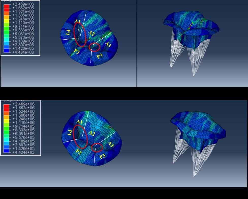
75 61 Figure 30: Comparison of Maximum In Plane (absolute) stress between (a) IA-FeMesh generated mesh and (b) ANSYS generated mesh at peak systole (t = 0.2 sec). Figure 31: Comparison of Von Mises stress between (a) IA-FeMesh generated mesh and (b) ANSYS generated mesh at peak systole (t = 0.2 sec).
 between (a)ansys generated mesh (b)")

 IA-FeMesh generated mesh and (b)")
76 62 Figure 32: Comparison of contact pressure (CPRESS) between (a)ansys generated mesh (b) IA-FEMesh generated mesh to verify the zone of regurgitation. Figure 33: Comparison of Von Mises stress between (a) IA-FeMesh generated mesh and (b) ANSYS generated mesh at peak diastole (t = 0.8 sec).
 ANSYS generated mesh at peak systole (t = 0.")
77 Figure 34: Comparison of Maximum In Plane (absolute) stress between (a) IA-FeMesh generated mesh and (b) ANSYS generated mesh at peak systole (t = 0.2 sec). 63
 IA-FEMesh generated fine mesh at peak systole (t = 0.2 sec).")
 IA-FEMesh generated fine mesh to verify the zone of")
78 64 Figure 35: Comparison of Von Mises stress between (a) IA-FeMesh generated coarse mesh, (b) ANSYS generated mesh and (c) IA-FEMesh generated fine mesh at peak systole (t = 0.2 sec). Figure 36: Comparison of contact pressure (CPRESS) between (a)ansys generated mesh (b) IA-FEMesh generated coarse mesh and (c) IA-FEMesh generated fine mesh to verify the zone of regurgitation.
ia-femesh generated fine mesh at peak diastole (t = 0.8 sec).")
79 Figure 37: Comparison of Von Mises stress between (a) IA-FEMesh generated coarse mesh, (b) ANSYS generated mesh and (c)ia-femesh generated fine mesh at peak diastole (t = 0.8 sec). 65
 ANSYS generated mesh and (c) IA-FEMesh generated fine mesh at peak systole (t = 0.2 sec).")

80 66 Figure 38: Comparison of Maximum In Plane (absolute) stress between (a) IA-FEMesh generated coarse mesh, (a) ANSYS generated mesh and (c) IA-FEMesh generated fine mesh at peak systole (t = 0.2 sec). Figure 39: Simulation of the quadrangular resection technique. From left: Cut geometry obtained by cutting in the surgical toolkit, Von Mises stress distribution after application of displacement boundary conditions on cut edge.


81 67 Figure 40: Von Mises stress distribution on the model post-cutting by generating chordae and applying cardiac cycle pressure data. Figure 41: Triangular resection technique results post-cutting by application of displacement boundary conditions for simulating suturing in the surgical toolkit for patient 2.


82 Figure 42: Quadrangular resection technique results post-cutting by applying displacement boundary conditions for simulating suturing in the surgical toolkit for patient 3. 68

83 Figure 43: Summary of the available features and future work to be done in the surgical toolkit. 69
Finite Element Modeling of the Mitral Valve and Mitral Valve Repair
 Finite Element Modeling of the Mitral Valve and Mitral Valve Repair Iain Baxter A thesis submitted to the Faculty of Graduate and Postdoctoral Studies in partial fulfillment of the requirements for the
Outcomes of Mitral Valve Repair for Mitral Regurgitation Due to Degenerative Disease
 Outcomes of Mitral Valve Repair for Mitral Regurgitation Due to Degenerative Disease TIRONE E. DAVID, MD ; SEMIN THORAC CARDIOVASC SURG 19:116-120c 2007 ELSEVIER INC. PRESENTED BY INTERN 許士盟 Mitral valve
8/31/2016. Mitraclip in Matthew Johnson, MD
 Mitraclip in 2016 Matthew Johnson, MD 1 Abnormal Valve Function Valve Stenosis Obstruction to valve flow during that phase of the cardiac cycle when the valve is normally open. Hemodynamic hallmark - pressure
Valve Analysis and Pathoanatomy: THE MITRAL VALVE
 : THE MITRAL VALVE Marc R. Moon, M.D. John M. Shoenberg Chair in CV Disease Chief, Cardiac Surgery Washington University School of Medicine, St. Louis, MO Secretary, American Association for Thoracic Surgery
MITRAL STENOSIS. Joanne Cusack
 MITRAL STENOSIS Joanne Cusack BSE Breakdown Recognition of rheumatic mitral stenosis Qualitative description of valve and sub-valve calcification and fibrosis Measurement of orifice area by planimetry
Patient-Specific Computational Simulation of the Mitral Valve Function Using Three-Dimensional Echocardiography
 Patient-Specific Computational Simulation of the Mitral Valve Function Using Three-Dimensional Echocardiography Y. Rim 1, S. T. Laing 1, P. Kee 1, K. B. Chandran 2, D. D. McPherson 1 and H. Kim 1 1 Department
Surgical Repair of the Mitral Valve Presenter: Graham McCrystal Cardiothoracic Surgeon Christchurch Public Hospital
 Mitral Valve Surgical intervention Graham McCrystal Chairs: Rajesh Nair & Gerard Wilkins Surgical Repair of the Mitral Valve Presenter: Graham McCrystal Cardiothoracic Surgeon Christchurch Public Hospital
Echocardiographic Evaluation of Primary Mitral Regurgitation
 Echocardiographic Evaluation of Primary Mitral Regurgitation Roberto M Lang, MD 0-10 o ME 4CH Med A2 P2 50-70 o Commissural P3 P1 A2 80-100 o ME 2CH P3 A2 A1 A1 125-135 o - ME Long axis P2 A2 P3 A3 P2
MITRAL REGURGITATION ECHO PARAMETERS TOOL
 Comprehensive assessment of qualitative and quantitative parameters, along with the use of standardized nomenclature when reporting echocardiographic findings, helps to better define a patient s MR and
TSDA Boot Camp September 13-16, Introduction to Aortic Valve Surgery. George L. Hicks, Jr., MD
 TSDA Boot Camp September 13-16, 2018 Introduction to Aortic Valve Surgery George L. Hicks, Jr., MD Aortic Valve Pathology and Treatment Valvular Aortic Stenosis in Adults Average Course (Post mortem data)
The production of murmurs is due to 3 main factors:
 Heart murmurs The production of murmurs is due to 3 main factors: high blood flow rate through normal or abnormal orifices forward flow through a narrowed or irregular orifice into a dilated vessel or
Historical perspective R1 黃維立
 Degenerative mitral valve disease refers to a spectrum of conditions in which morphologic changes in the connective tissue of the mitral valve cause structural lesions that prevent normal function of the
The production of murmurs is due to 3 main factors:
 Heart murmurs The production of murmurs is due to 3 main factors: high blood flow rate through normal or abnormal orifices forward flow through a narrowed or irregular orifice into a dilated vessel or
Posterior leaflet prolapse is the most common lesion seen
 Techniques for Repairing Posterior Leaflet Prolapse of the Mitral Valve Robin Varghese, MD, MS, and David H. Adams, MD Posterior leaflet prolapse is the most common lesion seen in degenerative mitral valve
Case 47 Clinical Presentation
 93 Case 47 C Clinical Presentation 45-year-old man presents with chest pain and new onset of a murmur. Echocardiography shows severe aortic insufficiency. 94 RadCases Cardiac Imaging Imaging Findings C
JOINT MEETING 2 Tricuspid club Chairpersons: G. Athanassopoulos, A. Avgeropoulou, M. Khoury, G. Stavridis
 JOINT MEETING 2 Tricuspid club Chairpersons: G. Athanassopoulos, A. Avgeropoulou, M. Khoury, G. Stavridis Similarities and differences in Tricuspid vs. Mitral Valve Anatomy and Imaging. Echo evaluation
PROSTHETIC VALVE BOARD REVIEW
 PROSTHETIC VALVE BOARD REVIEW The correct answer D This two chamber view shows a porcine mitral prosthesis with the typical appearance of the struts although the leaflets are not well seen. The valve
Part II: Fundamentals of 3D Echocardiography: Acquisition and Application
 Part II: Fundamentals of 3D Echocardiography: Acquisition and Application Dr. Bruce Bollen 3D matrix array TEE probes provide options for both 2D and 3D imaging. Indeed, their utility in obtaining multiple
The Edge-to-Edge Technique f For Barlow's Disease
 The Edge-to-Edge Technique f For Barlow's Disease Ottavio Alfieri, Michele De Bonis, Elisabetta Lapenna, Francesco Maisano, Lucia Torracca, Giovanni La Canna. Department of Cardiac Surgery, San Raffaele
Supervisors: Dr. ir. Matthieu De Beule, Prof. dr. ir. Benedict Verhegghe Counsellors: Tim Dezutter, dhr. Philippe Bertrand
 Simulation tools for mitral valve repair Viktoriya Antonova Supervisors: Dr. ir. Matthieu De Beule, Prof. dr. ir. Benedict Verhegghe Counsellors: Tim Dezutter, dhr. Philippe Bertrand Master's dissertation
Basic principles of Rheumatic mitral valve Repair
 Basic principles of Rheumatic mitral valve Repair Prof. Gebrine El Khoury, MD DEPARTMENT OF CARDIOVASCULAR AND THORACIC SURGERY ST. LUC HOSPITAL - BRUSSELS, BELGIUM 1 Rheumatic MV disease MV repair confers
Effect of leaflet-to-chordae contact interaction on computational mitral valve evaluation
 Rim et al. BioMedical Engineering OnLine 2014, 13:31 RESEARCH Open Access Effect of leaflet-to-chordae contact interaction on computational mitral valve evaluation Yonghoon Rim, David D McPherson and Hyunggun
Χειρουργική Αντιμετώπιση της Ανεπάρκειας της Μιτροειδούς Βαλβίδας
 Χειρουργική Αντιμετώπιση της Ανεπάρκειας της Μιτροειδούς Βαλβίδας Dr Χρήστος ΑΛΕΞΙΟΥ MD, PhD, FRCS(Glasgow), FRCS(CTh), CCST(UK) Consultant Cardiothoracic Surgeon Normal Mitral Valve Function Mitral Regurgitation
I (312) Mitral Regurgitation What Should You Know?
 Mitral Regurgitation What Should You Know?") Mitral Regurgitation What Should You Know? Table of Contents What is Mitral Regurgitation? 3 What are the Symptoms? 4 What are the risks? 5 Who Gets Mitral Regurgitation? 6 Diagnosing Mitral Regurgitation
Mitral Regurgitation What Should You Know? Table of Contents What is Mitral Regurgitation? 3 What are the Symptoms? 4 What are the risks? 5 Who Gets Mitral Regurgitation? 6 Diagnosing Mitral Regurgitation
How to assess ischaemic MR?
 ESC 2012 How to assess ischaemic MR? Luc A. Pierard, MD, PhD, FESC, FACC Professor of Medicine Head, Department of Cardiology University Hospital Sart Tilman, Liège ESC 2012 No conflict of interest Luc
Atrioventricular valve repair: The limits of operability
 Atrioventricular valve repair: The limits of operability Francis Fynn-Thompson, MD Co-Director, Center for Airway Disorders Surgical Director, Pediatric Mechanical Support Program Surgical Director, Heart
Index. B B-type natriuretic peptide (BNP), 76
, 76") Index A ACCESS-EU registry, 158 159 Acute kidney injury (AKI), 76, 88 Annular enlargement, RV, 177 178 Annuloplasty chordal cutting, 113 complete ring, 99 etiology-specific ring, 100 evolution, 98 flexible
Index A ACCESS-EU registry, 158 159 Acute kidney injury (AKI), 76, 88 Annular enlargement, RV, 177 178 Annuloplasty chordal cutting, 113 complete ring, 99 etiology-specific ring, 100 evolution, 98 flexible
ICE: Echo Core Lab-CRF
 APPENDIX 1 ICE: Echo Core Lab-CRF Study #: - Pt Initials: 1. Date of study: / / D D M M M Y Y Y Y 2. Type of Study: TTE TEE 3. Quality of Study: Poor Moderate Excellent Ejection Fraction 4. Ejection Fraction
Certificate in Clinician Performed Ultrasound (CCPU) Syllabus. Rapid Cardiac Echo (RCE)
 Syllabus. Rapid Cardiac Echo (RCE)") Certificate in Clinician Performed Ultrasound (CCPU) Syllabus Rapid Cardiac Echo (RCE) Purpose: Rapid Cardiac Echocardiography (RCE) This unit is designed to cover the theoretical and practical curriculum
Certificate in Clinician Performed Ultrasound (CCPU) Syllabus Rapid Cardiac Echo (RCE) Purpose: Rapid Cardiac Echocardiography (RCE) This unit is designed to cover the theoretical and practical curriculum
Mitral Regurgitation
 UW MEDICINE PATIENT EDUCATION Mitral Regurgitation Causes, symptoms, diagnosis, and treatment This handout describes mitral regurgitation, a disease of the mitral valve. It explains how this disease is
Despite advances in our understanding of the pathophysiology
 Suture Relocation of the Posterior Papillary Muscle in Ischemic Mitral Regurgitation Benjamin B. Peeler MD,* and Irving L. Kron MD,*, *Department of Cardiovascular Surgery, University of Virginia, Charlottesville,
Echocardiographic Evaluation of Aortic Valve Prosthesis
 Echocardiographic Evaluation of Aortic Valve Prosthesis Amr E Abbas, MD, FACC, FASE, FSCAI, FSVM, RPVI Co-Director, Echocardiography, Director, Interventional Cardiology Research, Beaumont Health System
Degenerative Mitral Regurgitation: Etiology and Natural History of Disease and Triggers for Intervention
 Degenerative Mitral Regurgitation: Etiology and Natural History of Disease and Triggers for Intervention John N. Hamaty D.O. FACC, FACOI November 17 th 2017 I have no financial disclosures Primary Mitral
3D Printing & Echocardiography
 ASE SOTA Feb 19, 2018 3D Printing & Echocardiography Stephen H. Little, MD John S. Dunn Chair in Cardiovascular Research and Education, Associate professor, Weill Cornell Medicine Disclosures Personal
When Does 3D Echo Make A Difference?
 When Does 3D Echo Make A Difference? Wendy Tsang, MD, SM Assistant Professor, University of Toronto Toronto General Hospital, University Health Network 1 Practical Applications of 3D Echocardiography Recommended
By the end of this session, the student should be able to:
 Valvular Heart disease HVD By Dr. Ashraf Abdelfatah Deyab VHD- Objectives By the end of this session, the student should be able to: Define and classify valvular heart disease. Enlist the causes of acquired
The Key Questions in Mitral Valve Interventions. Where Are We in 2018?
 The Key Questions in Mitral Valve Interventions Where Are We in 2018? Gilles D. DREYFUS, MD, FRCS, FESC Professor of Cardiothoracic Surgery 30 GIORNATE CARDIOLOGICHE TORINESI - OCT 2018 Are guidelines
Disclosure Statement of Financial Interest Saibal Kar, MD, FACC
 MitraClip Therapy Saibal Kar, MD, FACC, FAHA, FSCAI Director of Interventional Cardiac Research Program Director, Interventional Cardiology Heart Institute, Cedars-Sinai Medical Center, Los Angeles, CA
Imaging MV. Jeroen J. Bax Leiden University Medical Center The Netherlands Davos, feb 2015
 Imaging MV Jeroen J. Bax Leiden University Medical Center The Netherlands Davos, feb 2015 MV/MR: information needed on.. 1. MV anatomy 2. MR etiology - primary vs secondary 3. MR severity quantification
Copyright 2017 American College of Emergency Physicians. All rights reserved.
 POLICY Approved April 2017 Guidelines for the Use of Transesophageal Echocardiography (TEE) in the ED for Cardiac Arrest Approved by the ACEP Board of Directors April 2017 1. Introduction The American
Functional anatomy of the aortic root. ΔΡΟΣΟΣ ΓΕΩΡΓΙΟΣ Διεσθσνηής Καρδιοθωρακοτειροσργικής Κλινικής Γ.Ν. «Γ. Παπανικολάοσ» Θεζζαλονίκη
 Functional anatomy of the aortic root ΔΡΟΣΟΣ ΓΕΩΡΓΙΟΣ Διεσθσνηής Καρδιοθωρακοτειροσργικής Κλινικής Γ.Ν. «Γ. Παπανικολάοσ» Θεζζαλονίκη What is the aortic root? represents the outflow tract from the LV provides
Finite Element Analysis for Edge-to-Edge Technique to Treat Post-Mitral Valve Repair Systolic Anterior Motion
 Acta of Bioengineering and Biomechanics Vol. 6, No. 4, 04 Original paper DOI: 0.577/ABB-0008-04-0 Finite Element Analysis for Edge-to-Edge Technique to Treat Post-Mitral Valve Repair Systolic Anterior
MR echo case. N.Koutsogiannis Department of Cardiology University Hospital Of Patras
 MR echo case N.Koutsogiannis Department of Cardiology University Hospital Of Patras Case A 35 years old male came to the echo lab for a third opinion for his valvulopathy. He reports a long standing MR
Chapter 24: Diagnostic workup and evaluation: eligibility, risk assessment, FDA guidelines Ashwin Nathan, MD, Saif Anwaruddin, MD, FACC Penn Medicine
 Chapter 24: Diagnostic workup and evaluation: eligibility, risk assessment, FDA guidelines Ashwin Nathan, MD, Saif Anwaruddin, MD, FACC Penn Medicine Mitral regurgitation, regurgitant flow between the
Revealing new insights. irotate electronic rotation and xplane adjustable biplane imaging. Ultrasound cardiology. irotate and xplane
 Ultrasound cardiology irotate and xplane Revealing new insights irotate electronic rotation and xplane adjustable biplane imaging Annemien van den Bosch and Jackie McGhie Department of Cardiology, Erasmus
What echo measurements are key prior to MitraClip?
 APHP CHU Bichat - Claude Bernard What echo measurements are key prior to MitraClip? Eric Brochet,MD Cardiology Department Hopital Bichat Paris France No disclosure Conflict of interest Case 69 y.o man
THE FOLDING LEAFLET. Rafael García Fuster. Cardiac Surgery Department University General Hospital of Valencia
 THE FOLDING LEAFLET Rafael García Fuster Cardiac Surgery Department University General Hospital of Valencia School of Medicine Catholic University of Valencia San Vicente Mártir SPAIN Carpentier s principles
Effect of Congenital Anomalies of the Papillary Muscles on Mitral Valve Function
 J. Med. Biol. Eng. (2015) 35:104 112 DOI 10.1007/s40846-015-0011-1 ORIGINAL ARTICLE Effect of Congenital Anomalies of the Papillary Muscles on Mitral Valve Function Yonghoon Rim David D. McPherson Hyunggun
Outline. EuroScore II. Society of Thoracic Surgeons Score. EuroScore II
 SURGICAL RISK IN VALVULAR HEART DISEASE: WHAT 2D AND 3D ECHO CAN TELL YOU AND WHAT THEY CAN'T Ernesto E Salcedo, MD Professor of Medicine University of Colorado School of Medicine Director of Echocardiography
A novel mathematical technique to assess of the mitral valve dynamics based on echocardiography
 ORIGINAL ARTICLE A novel mathematical technique to assess of the mitral valve dynamics based on echocardiography Mersedeh Karvandi 1 MD, Saeed Ranjbar 2,* Ph.D, Seyed Ahmad Hassantash MD 2, Mahnoosh Foroughi
Milind Desai Christine Jellis Teerapat Yingchoncharoen Editors. An Atlas of Mitral Valve Imaging
 Milind Desai Editors An Atlas of Mitral Valve Imaging 123 An Atlas of Mitral Valve Imaging Milind Desai Editors An Atlas of Mitral Valve Imaging Editors Milind Desai Department of Cardiovascular Medicine
Iatrogenic pathology of the heart:
 Iatrogenic pathology of the heart: Complications of mitral valve plasty and replacement Patrick Bruneval D pt of Pathology Hôpital Européen Georges Pompidou Enterprise Interest None Mitral valve surgery
MITRAL VALVE DISEASE- ASSESSMENT AND MANAGEMENT. Irene Frantzis P year, SGUL Sheba Medical Center
 MITRAL VALVE DISEASE- ASSESSMENT AND MANAGEMENT Irene Frantzis P year, SGUL Sheba Medical Center MITRAL VALVE DISEASE Mitral Valve Regurgitation Mitral Valve Stenosis Mitral Valve Prolapse MITRAL REGURGITATION
TAVR: Echo Measurements Pre, Post And Intra Procedure
 2017 ASE Florida, Orlando, FL October 10, 2017 8:00 8:25 AM 25 min TAVR: Echo Measurements Pre, Post And Intra Procedure Muhamed Sarić MD, PhD, MPA Director of Noninvasive Cardiology Echo Lab Associate
25 different brand names >44 different models Sizes mm
 Types of Prosthetic Valves BIOLOGIC STENTED Porcine xenograft Pericardial xenograft STENTLESS Porcine xenograft Pericardial xenograft Homograft (allograft) Autograft PERCUTANEOUS MECHANICAL Bileaflet Single
Introduction. Cardiac Imaging Modalities MRI. Overview. MRI (Continued) MRI (Continued) Arnaud Bistoquet 12/19/03
 MRI (Continued) Arnaud Bistoquet 12/19/03") Introduction Cardiac Imaging Modalities Arnaud Bistoquet 12/19/03 Coronary heart disease: the vessels that supply oxygen-carrying blood to the heart, become narrowed and unable to carry a normal amount
Introduction Cardiac Imaging Modalities Arnaud Bistoquet 12/19/03 Coronary heart disease: the vessels that supply oxygen-carrying blood to the heart, become narrowed and unable to carry a normal amount
PART II ECHOCARDIOGRAPHY LABORATORY OPERATIONS ADULT TRANSTHORACIC ECHOCARDIOGRAPHY TESTING
 PART II ECHOCARDIOGRAPHY LABORATORY OPERATIONS ADULT TRANSTHORACIC ECHOCARDIOGRAPHY TESTING STANDARD - Primary Instrumentation 1.1 Cardiac Ultrasound Systems SECTION 1 Instrumentation Ultrasound instruments
The clinical problem of atrioventricular valve regurgitation
 Mitral Regurgitation in Congenital Heart Defects: Surgical Techniques for Reconstruction Richard G. Ohye Mitral valve regurgitation (MR) is an important source of morbidity and mortality worldwide. While
Case # 1. Page: 8. DUKE: Adams
 Case # 1 Page: 8 1. The cardiac output in this patient is reduced because of: O a) tamponade physiology O b) restrictive physiology O c) coronary artery disease O d) left bundle branch block Page: 8 1.
Cardiac Surgery A Resource of Experimental Design
 Cardiac Surgery A Resource of Experimental Design Complete Transposition: a. Atrial switch the chronically systemic right ventricle b. Arterial switch the suddenly systemic left ventricle Fontan operation
Congenital. Unicuspid Bicuspid Quadricuspid
 David Letterman s Top 10 Aortic Stenosis The victim can be anyone: Echo is the question and the answer!!!! Hilton Head Island Echocardiography Conference 2012 Timothy E. Paterick, MD, JD, MBA Christopher
DEVELOPMENT OF A CRYO-ANCHORING AND RADIOFREQUENCY ABLATION CATHETER FOR PERCUTANEOUS TREATMENT OF MITRAL VALVE PROLAPSE. Steven Michael Boronyak
 DEVELOPMENT OF A CRYO-ANCHORING AND RADIOFREQUENCY ABLATION CATHETER FOR PERCUTANEOUS TREATMENT OF MITRAL VALVE PROLAPSE By Steven Michael Boronyak Dissertation Submitted to the Faculty of the Graduate
Eva Maria Delmo Walter Takeshi Komoda Roland Hetzer
 Surgical repair of the congenitally malformed mitral valve leaflets in infants and children Eva Maria Delmo Walter Takeshi Komoda Roland Hetzer Deutsches Herzzentrum Berlin Germany Background and Objective
Valvular Heart Disease in Clinical Practice
 Valvular Heart Disease in Clinical Practice Michael Y. Henein Editor Valvular Heart Disease in Clinical Practice 123 Editor Michael Y. Henein Consultant Cardiologist Umea Heart Centre Umea University
Introduction. Aortic Valve. Outflow Tract and Aortic Valve Annulus
 Chapter 1: Surgical anatomy of the aortic and mitral valves Jordan RH Hoffman MD, David A. Fullerton MD, FACC University of Colorado School of Medicine, Department of Surgery, Division of Cardiothoracic
Ischemic Mitral Regurgitation
 Ischemic Mitral Regurgitation Jean-Louis J. Vanoverschelde, MD, PhD Université catholique de Louvain Brussels, Belgium Definition Ischemic mitral regurgitation is mitral regurgitation due to complications
3D Printing & Echocardiography
 Echo Hawaii Jan 18, 2018 3D Printing & Echocardiography Stephen H. Little, MD John S. Dunn Chair in Cardiovascular Research and Education, Associate professor, Weill Cornell Medicine Rapid Prototyping
Bogdan A. Popescu. University of Medicine and Pharmacy Bucharest, Romania. EAE Course, Bucharest, April 2010
 Bogdan A. Popescu University of Medicine and Pharmacy Bucharest, Romania EAE Course, Bucharest, April 2010 This is how it started Mitral stenosis at a glance 2D echo narrow diastolic opening of MV leaflets
Image Analysis and Cytometry in Three-Dimensional Digital Reconstruction of Porcine Native Aortic Valve Leaflets
 Image Analysis and Cytometry in Three-Dimensional Digital Reconstruction of Porcine Native Aortic Valve Leaflets Introduction Chi Zheng, M1 - University of Pittsburgh; BSE - University of Michigan In association
Percutaneous Mitral Valve Repair
 Indiana Chapter of ACC November 15 th,2008 Percutaneous Mitral Valve Repair James B Hermiller, MD, FACC The Care Group, LLC St Vincent Hospital Indianapolis, IN Mechanisms of Mitral Regurgitation Mitral
Two semilunar valves. Two atrioventricular valves. Valves of the heart. Left atrioventricular or bicuspid valve Mitral valve
 The Heart 3 Valves of the heart Two atrioventricular valves Two semilunar valves Right atrioventricular or tricuspid valve Left atrioventricular or bicuspid valve Mitral valve Aortic valve Pulmonary valve
The stentless bioprosthesis has many salient features that
 Aortic Valve Replacement with the Medtronic Freestyle Xenograft Using the Subcoronary Implantation Technique D. Michael Deeb, MD The stentless bioprosthesis has many salient features that make it an attractive
Percutaneous Mitral Valve Intervention: QuantumCor Device
 Percutaneous Mitral Valve Intervention: QuantumCor Device RICHARD R. HEUSER, MD, FACC, FACP, FESC Director Of Cardiology, St. Luke s Medical Center, Phoenix, Arizona Medical Director, Phoenix Heart Center,
Computer Aided Surgery (CAS) for Abdominal Aortic Aneurysm (AAA)
 for Abdominal Aortic Aneurysm (AAA)") Computer Aided Surgery (CAS) for Abdominal Aortic Aneurysm (AAA) Aurélien Dumenil Pierre Louat Thierry Marchal Michel Rochette 2009 ANSYS, Inc. All rights reserved. 1 ANSYS, Inc. Proprietary Outline Clinical
Computer Aided Surgery (CAS) for Abdominal Aortic Aneurysm (AAA) Aurélien Dumenil Pierre Louat Thierry Marchal Michel Rochette 2009 ANSYS, Inc. All rights reserved. 1 ANSYS, Inc. Proprietary Outline Clinical
Repair or Replacement
 Surgical intervention post MitraClip Device: Repair or Replacement Saudi Heart Association, February 21-24 Rüdiger Lange, MD, PhD Nicolo Piazza, MD, FRCPC, FESC German Heart Center, Munich, Germany Division
MEMO 3D. The true reflection of the mitral annulus. Natural physiological 3D motion
 MEMO 3D TM The true reflection of the mitral annulus Natural physiological 3D motion Imagine... if there was one annuloplasty ring that provided an optimal solution across the entire spectrum of mitral
Mitral Valve Disease, When to Intervene
 Mitral Valve Disease, When to Intervene Swedish Heart and Vascular Institute Ming Zhang MD PhD Interventional Cardiology Structure Heart Disease Conflict of Interest None Current ACC/AHA guideline Stages
Index of subjects. effect on ventricular tachycardia 30 treatment with 101, 116 boosterpump 80 Brockenbrough phenomenon 55, 125
 145 Index of subjects A accessory pathways 3 amiodarone 4, 5, 6, 23, 30, 97, 102 angina pectoris 4, 24, 1l0, 137, 139, 140 angulation, of cavity 73, 74 aorta aortic flow velocity 2 aortic insufficiency
HISTORY. Question: How do you interpret the patient s history? CHIEF COMPLAINT: Dyspnea of two days duration. PRESENT ILLNESS: 45-year-old man.
 HISTORY 45-year-old man. CHIEF COMPLAINT: Dyspnea of two days duration. PRESENT ILLNESS: His dyspnea began suddenly and has been associated with orthopnea, but no chest pain. For two months he has felt
Ο ΡΟΛΟΣ ΤΩΝ ΚΟΛΠΩΝ ΣΤΗ ΛΕΙΤΟΥΡΓΙΚΗ ΑΝΕΠΑΡΚΕΙΑ ΤΩΝ ΚΟΛΠΟΚΟΙΛΙΑΚΩΝ ΒΑΛΒΙΔΩΝ
 Ο ΡΟΛΟΣ ΤΩΝ ΚΟΛΠΩΝ ΣΤΗ ΛΕΙΤΟΥΡΓΙΚΗ ΑΝΕΠΑΡΚΕΙΑ ΤΩΝ ΚΟΛΠΟΚΟΙΛΙΑΚΩΝ ΒΑΛΒΙΔΩΝ Ανδρέας Κατσαρός Καρδιολόγος Επιµ. Α Καρδιοχειρ/κών Τµηµάτων Γ.Ν.Α. Ιπποκράτειο ΚΑΜΙΑ ΣΥΓΚΡΟΥΣΗ ΣΥΜΦΕΡΟΝΤΩΝ ΑΝΑΦΟΡΙΚΑ ΜΕ ΤΗΝ ΠΑΡΟΥΣΙΑΣΗ
Mitral Valve Disease. Prof. Sirchak Yelizaveta Stepanovna
 Mitral Valve Disease Prof. Sirchak Yelizaveta Stepanovna Fall 2008 Mitral Valve Stenosis Lecture Outline Mitral Stenosis Mitral Regurgitation Etiology Pathophysiology Clinical features Diagnostic testing
A new era in cardiac valve surgery has begun...
 THE CENTER FOR VALVE SURGERY A new era in cardiac valve surgery has begun... Good Help to Those in Need Rawn Salenger, MD, FACS, Director, The Center for Valve Surgery Edward F. Lundy, MD, PhD, Chief of
Rheumatic fever and rheumatic heart disease still remain a. The Rheumatic Mitral Valve and Repair Techniques in Children. Afksendiyos Kalangos
 The Rheumatic Mitral Valve and Repair Techniques in Children Afksendiyos Kalangos The mitral valve is the most commonly affected valve in acute and chronic rheumatic heart disease in the first and second
Percutaneous Mitral Valve Repair
 Percutaneous Mitral Valve Repair MitraClip: Procedure, Data, Patient Selection Chad Rammohan, MD FACC Director, Cardiac Cath Lab El Camino Hospital Mountain View, California Mitral Regurgitation MitraClip
When should we intervene surgically in pediatric patient with MR?
 When should we intervene surgically in pediatric patient with MR? DR.SAUD A. BAHAIDARAH CONSULTANT, PEDIATRIC CARDIOLOGY ASSISTANT PROFESSOR OF PEDIATRICS HEAD OF CARDIOLOGY AND CARDIAC SURGERY UNIT KAUH
Annular Stabilization Techniques in the Context of Aortic Valve Repair
 Annular Stabilization Techniques in the Context of Aortic Valve Repair Prashanth Vallabhajosyula, MD MS University of Pennsylvania, Philadelphia, Pennsylvania 2 nd North American Aortic Valve Repair Symposium
Indications and Late Results of Aortic Valve Repair
 Indications and Late Results of Aortic Valve Repair Prof. Gebrine El Khoury Department of Cardiovascular and Thoracic Surgery Cliniques St. Luc Brussels, Belgium Aortic Valve Repair Question # 1 Can the
Contents 1 Computational Haemodynamics An Introduction 2 The Human Cardiovascular System
 Contents 1 Computational Haemodynamics An Introduction... 1 1.1 What is Computational Haemodynamics (CHD)... 1 1.2 Advantages of CHD... 3 1.3 Applications in the Cardiovascular System... 4 1.3.1 CHD as
Design and Simulation of Blocked Blood Vessel for Early Detection of Heart Diseases
 Proceedings of the 215 2nd International Symposium on Physics and Technology of Sensors, 8-1th March, 215, Pune, India Design and Simulation of Blocked Blood Vessel for Early Detection of Heart Diseases
PATIENT BOOKLET MEDTRONIC SURGICAL VALVE REPLACEMENT. Tissue Valve for Aortic and Mitral Valve Replacement
 PATIENT BOOKLET MEDTRONIC SURGICAL VALVE REPLACEMENT Tissue Valve for Aortic and Mitral Valve Replacement ARE MEDTRONIC SURGICAL TISSUE HEART VALVES RIGHT FOR YOU? Medtronic surgical heart valves are for
Regurgitant Lesions. Bicol Hospital, Legazpi City, Philippines July Gregg S. Pressman MD, FACC, FASE Einstein Medical Center Philadelphia, USA
 Regurgitant Lesions Bicol Hospital, Legazpi City, Philippines July 2016 Gregg S. Pressman MD, FACC, FASE Einstein Medical Center Philadelphia, USA Aortic Insufficiency Valve anatomy and function LVOT and
ARTIFACTS: THEORY AND ILLUSTRATIVE EXAMPLES
 ARTIFACTS: THEORY AND ILLUSTRATIVE EXAMPLES Robert A. Levine, M.D. Marielle Scherrer-Crosbie, M.D. Eric M. Isselbacher, M.D. 60 year old man Cardiac source of embolus? NAME THAT MASS! 1 NAME THAT MASS!
Biomechanical implications of congenitally bicuspid aortic valves: a finite element analysis of patient-specific geometry
 University of Iowa Iowa Research Online Theses and Dissertations Spring 2013 Biomechanical implications of congenitally bicuspid aortic valves: a finite element analysis of patient-specific geometry Paul
ρ = 4(νp)2 Scale -200 to 200 V = m/s Grad = 34 mmhg V = 1.9 m/s Grad = 14 mmhg Types
2 Scale -200 to 200 V = m/s Grad = 34 mmhg V = 1.9 m/s Grad = 14 mmhg Types") Pre and Post Operative Evaluation of the Aorta and Aortic Valve Andrew J. Bierhals, MD The Pre and Post-Operative Evaluation of the Aorta and Aortic Valve Andrew Bierhals, MD, MPH Mallinckrodt Institute
Pre and Post Operative Evaluation of the Aorta and Aortic Valve Andrew J. Bierhals, MD The Pre and Post-Operative Evaluation of the Aorta and Aortic Valve Andrew Bierhals, MD, MPH Mallinckrodt Institute
Adult Echocardiography Examination Content Outline
 Adult Echocardiography Examination Content Outline (Outline Summary) # Domain Subdomain Percentage 1 2 3 4 5 Anatomy and Physiology Pathology Clinical Care and Safety Measurement Techniques, Maneuvers,
ARTIFACTS: THEORY AND ILLUSTRATIVE EXAMPLES
 ARTIFACTS: THEORY AND ILLUSTRATIVE EXAMPLES Robert A. Levine, M.D. Marielle Scherrer-Crosbie, M.D. Eric M. Isselbacher, M.D. No conflicts of interest Philippe Bertrand, Pieter Vendervoort, Hasselt and
Echo Week - Learning Objectives
 Echo Week - Learning Objectives Sunday, February 25 5-7 pm Physics Review Moderator: Mark Taylor, MD 1. Understand the ultrasound physics and apply it to image creation and optimization 2. Infer the interaction
MITRAL VALVE FORCE BALANCE: A QUANTITATIVE ASSESSMENT OF ANNULAR AND SUBVALVULAR FORCES
 MITRAL VALVE FORCE BALANCE: A QUANTITATIVE ASSESSMENT OF ANNULAR AND SUBVALVULAR FORCES A Dissertation Presented to The Academic Faculty by Andrew W. Siefert In Partial Fulfillment of the Requirements
What Is Valvular Heart Disease? Heart valve disease occurs when your heart's valves do not work the way they should.
 What Is Valvular Heart Disease? Heart valve disease occurs when your heart's valves do not work the way they should. How Do Heart Valves Work? MAINTAIN ONE-WAY BLOOD FLOW THROUGH YOUR HEART The four heart