Technique Guide. LISS DF. The less invasive stabilization system for distal femur fractures.
|
|
|
- Drusilla Phillips
- 6 years ago
- Views:
Transcription

1 Technique Guide LISS DF. The less invasive stabilization system for distal femur fractures.
2
3 Table of Contents Introduction Less Invasive Stabilization System LISS 2 AO Principles 4 Indications 5 Clinical Cases 6 Surgical Technique Preoperative Planning 8 Preparation 11 Plate Insertion 16 A Insertion of Self-Drilling Monocortical Screws 20 B Insertion of Self-Tapping Bicortical Screws 25 C Insertion of Periprosthetic Screws 29 Option: Pulling Device ( Whirly Bird ) 32 Implant Removal 33 Tips 35 Instruments for Minimally Invasive Surgery 36 Product Information Implants 37 Instruments 39 Sets 42 Bibliography 44 Stardrive Hex drive Image intensifier control Warning This description is not sufficient for immediate application of the instrumentation. Instruction by a surgeon experienced in handling this instrumentation is highly recommended. Synthes 1


4 LISS DF. The less invasive stabilization system for distal femur fractures. Anatomically precontoured low profile plates Reduced soft tissue problems No need for plate contouring Note: Excessive and repetitive bending is not recommended as it may weaken the plate. Angular stability Prevents screw loosening as well as primary and secondary loss of reduction Allows early functional mobilization As an internal fixator the plate preserves bone vascularization Offers improved purchase in osteoporotic bone Less invasive procedure A radiolucent handle facilitates the insertion of the plate as well as accurate and hassle-free percutaneous placement of the screws. Additional instrumentation facilitate indirect reduction. Wide variety of anatomically precontoured plates LCP DF and PLT plates Available in stainless steel and titanium alloy (TAN) Left and right versions LCP DF plates in eight lengths with 5 to 19 holes in the shaft Long LCP DF plates (15 to 19 holes) available in sterile only Wide variety of screws Self-tapping or self-drilling locking screws Periprosthetic locking screws with blunt tip for periprosthetic fractures Cortex screws Available in stainless steel and titanium 2 Synthes LISS DF Technique Guide

5 LISS instrumentation for Stardrive and Hex drive The torque-limiting screwdriver, the screwdriver shaft and the cleaning instrument are available for screws with Stardrive and Hex drive. Synthes 3
6 AO Principles In 1958, the AO formulated four basic principles, which have become the guidelines for internal fixation: 1 Anatomic reduction Fixation of extra- and intra-articular distal femur fractures with the precontoured LCP DF plates allows for anatomic reduction. Stable fixation Locking holes allow fixation with locking screws for angular stability. A fixed-angle construct is advantageous in osteoporotic bone and multifragment fractures where traditional screw purchase is compromised. Preservation of blood supply The LISS approach with its proven success preserves the blood supply through a minimally invasive surgical technique and minimal bone-to-plate contact. Early, active mobilization LISS provides stable fracture fixation with minimal trauma to the vascular supply. This helps improve the environment for bone healing, accelerating the patient s return to previous mobility and function. 1 Müller ME, Allgöwer M, Schneider R, Willenegger H (1991) AO Manual of Internal Fixation. 3rd Edition. Berlin: Springer 4 Synthes LISS DF Technique Guide

7 Indications Indications LCP DF is indicated for the stabilization of fractures of the distal femur. These include: Distal shaft fractures Supracondylar fractures Intra-articular fractures Periprosthetic fractures Synthes 5


8 Clinical Cases Case 1 Male, 20 years old, polytrauma, fracture 33-C3 Preoperative Follow-up after 6 weeks Follow-up after 3 months Follow-up after 5 months 6 Synthes LISS DF Technique Guide


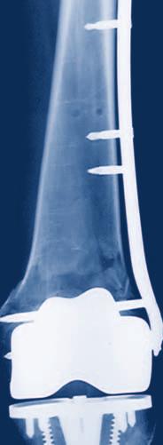
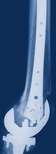
9 Case 2 Male, 76 years old, isolated fracture 33-B2 Preoperative Postoperative Follow-up after 4 weeks Synthes 7
10 E A B mm Caution: Due to variable magnification factors in x-rays, this template should be used for general pre-operative planning only. For use only with the Original AO System of Instruments and Implants A C/G B B mm Caution: Due to variable magnification factors in x-rays, this template should be used for general pre-operative planning only. For use only with the Original AO System of Instruments and Implants Synthes GmbH Eimattstrasse 3 CH-4436 Oberdorf Synthes GmbH Eimattstrasse 3 CH-4436 Oberdorf Preoperative Planning Use the x-ray templates for LCP DF (Art. No for right and for left femur) to determine the length of the plate and the position of the screws. Preoperative planning of lag screws may be necessary. LCP Distal Femur, right E D/F A C/G B D F C G F E/A/B D G C 1.10 Magnification Titanium St. Steel Holes Length (mm) S S S S S S AB /2010 Synthes, Inc. or its affiliates All rights reserved Synthes is trademark of Synthes, Inc. or its affiliates Ö öAB{ä LCP Distal Femur, left E D/F A D F E C G 1.10 Magnification D B/A/E F C G Titanium St. Steel Holes Length (mm) S S S S S S AB /2010 Synthes, Inc. or its affiliates All rights reserved Synthes is trademark of Synthes, Inc. or its affiliates Ö öABNä 8 Synthes LISS DF Technique Guide
11 Preoperative screw-length selection using an AP radiograph To select the proper screw length for the condyle, it is possible to perform a preoperative x-ray with the 50 mm wide calibrator and to use the table below. 1. Place the x-ray calibrator medially or laterally at the height of the condyle. 2. Take an AP radiograph of the distal femur. 3. Measure the width of the x-ray calibrator (XRC) on the radiograph. 4. Measure the maximum condyle width (MCW) on the radiograph. 5. Determine the real condyle width (RCW). RCW = 50 XRC MCW 6. Determine the screw lengths for the screw holes A to G using the table below. The positions A to G are indicated on the x-ray template and on the LISS DF insertion guide. Length of locking screws (mm) Real condyle width (RCW) Hole A Hole B Hole C Hole D Hole E Hole F Hole G mm mm mm mm Synthes 9
12 Preoperative Planning Example The length of the x-ray calibrator on the radiograph (XRC) is 55 mm (magnification 1.10). The maximum condyle width on the radiograph (MCW) amounts to 91 mm. RCW= = 83 mm The real condyle width (RCW) is therefore 83 mm. The screw lengths are therefore: Screw hole Screw length (mm) A 75 B 40 C 55 D 65 E 75 F 75 G 65 Important: The proper placement of the plate on the condyle is essential to ensure the correct screw length. 10 Synthes LISS DF Technique Guide
13 Preparation 1 Prepare required sets Instrument sets Set for LISS Instruments and or Insertion Handle, for DF and PLT Plates Set for LISS Instruments Stardrive and Insertion Handle, for DF and PLT Plates Optional instrument set Large Fragment Instrument Set Plate sets Plate Set LCP DF 4.5/5.0 (Stainless or Steel) Plate Set LCP DF 4.5/5.0 (TAN) Note on long plates: The LCP DF plates with 15 to 19 holes are available in sterile only and not part of a set. Therefore these articles have to be ordered as single items (for article numbers refer to page 37). Screw sets Modular Insert, for Modular Screw Rack, for Screws 5.0 mm, size 1/3, without Contents, Vario Case System Modular Insert, for Modular Screw Rack, for Screws 4.5 mm, size 1/3, without Contents, Vario Case System Power Tools* Compact Air Drive II AO/ASIF Quick Coupling, for Compact Air Drive and Power Drive Quick Coupling for Kirschner Wires 0.6 to 3.2 mm, for Compact Air Drive and Power Drive Battery Handpiece, modular, for Trauma Recon System Power Module, for Trauma Recon System Sterile Cover, for Trauma Recon System Lid for Battery Handpiece No , for Trauma Recon System AO/ASIF Quick Coupling, for Trauma Recon System Quick Coupling for Kirschner Wires 1.0 to 4.0 mm, for Trauma Recon System Torque Limiter, 4.0 Nm, for Trauma Recon System * For further information refer to the instructions for use for the Trauma Recon System ( ) or the Compact Air Drive ( ) Modular Insert, for Modular Screw Rack, for Screws 6.5 mm, size 1/3, without Contents, Vario Case System Modular Screw Rack, with Drawer, Measuring Block and Lid, length 200 mm, height 115 mm, size 1/2, without Contents, Vario Case System Synthes 11

14 Preparation 2 Position the patient Position the patient supine on a radiolucent table. The leg should be freely movable. The contralateral leg can be placed in an obstetric leg holder. Place the knee joint line slightly distal to the hinged part of the table to allow flexion of the knee during surgery. Avoid too strong a traction and a fully extended knee, as the forces of the gastrocnemius muscle would draw the distal fragment into recurvatum. This does not only make the reduction of the fracture difficult, but also endangers the popliteal artery and vein. In very short distal fragments, it is recommended to flex the lower leg to approximately 60. This also reduces the traction force of the gastrocnemius muscle. 12 Synthes LISS DF Technique Guide


15 3 Assemble the insertion instruments Instruments LISS Insertion Guide for Distal Femur, left or LISS Insertion Guide for Distal Femur, right Pin Wrench 4.5 mm Hole A Drill Sleeve for LISS Insertion Guide Stabilization Bolt for LISS Insertion Guide Fixation Bolt for LISS Insertion Guide 5 Insert the fixation bolt in hole A of the insertion guide. Place the insertion guide on the three-point locking mechanism of the plate. Synthes 13


16 Preparation Thread the fixation bolt into the plate. Thread the nut of the fixation bolt and lightly tighten it with the pin wrench. For a more stable fixation of the plate on the insertion guide during insertion, introduce the stabilization bolt with the drill sleeve in hole B and thread it into the plate. Hole B Hole A Note: To prevent tissue ingrowth and facilitate implant removal, close the unoccupied screw holes with screw hole inserts prior to inserting the plate. Use the torque-limiting screwdriver. The optimum torque is reached after one click. 14 Synthes LISS DF Technique Guide


17 4 Reduce the fracture In an intra-articular fracture, first reconstruct and stabilize the entire joint. The figure shows the possible positioning sites for lag screws in the condyles (in red). Take care to ensure that these lag screws will not collide with the screws inserted through the insertion guide. The fracture can be aligned manually by traction using a temporary knee-bridging external fixator or a distractor. Intraoperative x-ray or image-intensifier control is recommended to check the reduction. Possible positioning sites for lag screws (in red) The anteromedial insertion of a Schanz screw can be beneficial in distal fragment manipulation. 5 Surgical approaches Extra-articular fractures Perform a skin incision from Gerdy s tubercle about 80 mm in a proximal direction. Split the iliotibial tract in the direction of the fibres. Open the space between the lateral vastus and the periost. Distally, the lateral vastus muscle inserts mainly on the femoral ridge. There are no muscle insertions on the lateral periost or bone. The plate can be inserted into the space between the periost and the muscle. Intra-articular fractures In intra-articular fractures, an anterolateral arthrotomy providing good control of the reduction is recommended. This arthrotomy also allows a subsequent insertion of the plate and can be used to insert lag screws from medially. Synthes 15

18 Plate Insertion 1 Insert LISS Instruments Assembled Insertion Guide Trocar, length 162 mm, for No Use the assembled insertion guide to insert the plate between the lateral vastus muscle and the periost. Slide the plate proximally and ensure that its proximal end remains in constant contact with the bone. Position the distal end of the plate against the lateral condyle. To find the correct position, move the plate proximally and then back distally until the plate fits the condyle. Should the proximal end of the handle and the soft tissues impair the insertion of the plate, it is possible to remove the radiolucent proximal part of the handle for insertion. Due to its weight, the insertion guide tends to tilt dorsally. If the insertion guide points parallel to the floor with the patient in a supine position, the plate is externally rotated and no longer lies flat up against the lateral condyle. The fixation bolt must be oriented parallel to the patello-femoral joint. Consequently, the insertion guide shows an internal rotation of about 10. This occurrence is also visible in the AP view of an image intensifier. The plate must lie flat up against the condyle to ensure an optimal fit on the bone. 16 Synthes LISS DF Technique Guide

19 Once the plate is properly aligned with the bone, remove the drill sleeve and stabilization bolt from hole B. Insert the trocar through the drill sleeve in the most proximal hole of the plate. Perform a stab incision and push the drill sleeve and the trocar down to the plate. Check the correct position of the proximal part of the plate, either with the image intensifier or by direct palpation. Secure the position of the drill sleeve with the lateral screw on the insertion guide. Replace the trocar with a stabilization bolt. To close the frame, thread the stabilization bolt into the plate. Note: Due to soft tissues around the stabilization bolt, it will be difficult to change the position of the plate/handle assembly once the bolt has been inserted. Option: Check plate position with a Kirschner Wire Instrument Kirschner Wire 2.0 mm with threaded tip Use a Kirschner wire to check the correct position of the proximal part of the plate on the bone. Synthes 17
20 Plate Insertion 2 Fixate LISS temporarily with Kirschner wires Instrument Kirschner Wire 2.0 mm with threaded tip For preliminary fixation of the plate, use 2.0 mm Kirschner wires through the fixation and stabilization bolts. Carefully check the position of the plate and the length of the reduced injured limb. Once the reduction has been successfully completed and the plate has been positioned correctly, the locking screws can be inserted. 18 Synthes LISS DF Technique Guide
21 Alternative technique Instruments Aiming Device for Kirschner Wires, for LISS Insertion Guide Centering Sleeve for Kirschner Wire, length 184 mm, for No Kirschner Wire 2.0 mm with threaded tip If necessary, it is possible to use 2.0 mm Kirschner wires for the preliminary fixation along the full length of the plate. Use the aiming device for Kirschner wires to insert the wires on the ventral and dorsal side of the plate. Note that the distance between bone and plate should be kept as short as possible when inserting the wires, as they are arranged in a convergent way. After the insertion of the Kirschner wires, the distance between plate and bone can no longer be reduced. After removing the Kirschner wire sleeves and the aiming device, proximal/distal displacement and adjustment of the position of the plate can be carried out. At the same time, the lateral Kirschner wires prevent the plate from migrating into the sagittal plane. Once the correct position is determined, the plate can be locked temporarily with a Kirschner wire through the fixation bolt. Note: The aiming device can be used from hole 3 to hole 13. Synthes 19
22 A Insertion of Self-Drilling, Monocortical Locking Screws Screw placement depends on the type of fracture. The position of the screws should be chosen in accordance with established biomechanical principles for internal fixation. The screws should be inserted close to and remote from the fracture gap in the main fragments. Use at least four screws per fracture side. Once the initial screw has been inserted in each main fragment, length and rotation are defined. Ante- and recurvatum deformities can still be manipulated relatively well, whereas there are only limited correction possibilities for varus/valgus deformities. Therefore, it is recommended to insert the first screw in the distal fragment. The distal screws should be placed parallel to the knee joint. Then insert a screw in the proximal fragment. Important: If a screw has to be removed and reinserted, use the torque-limiting screwdriver and not the power tool. 20 Synthes LISS DF Technique Guide
23 1 Make stab incision Instruments Drill Sleeve for LISS Insertion Guide Trocar, length 162 mm, for No Make a stab incision and insert the trocar through the drill sleeve. 2 Determine screw length The length of the condylar screws can be deduced from the table on page 9. Use screws of 26 mm length in the diaphyseal region. Options In case of very thick cortex, pre-drill by using the pulling device ( ) or the drill bit 4.3 mm ( ). The insertion of the initial screw tends to push the bone medially, especially in case of dense bone and/or unstable reductions. The pulling device helps to solve this problem (see page 32). Synthes 21

24 A Insertion of Self-Drilling, Monocortical Locking Screws Option: Determine screw length with Kirschner wire Instruments Centering Sleeve for Kirschner Wires LISS Measuring Device for Kirschner Wires mm Kirschner wire, length 280 mm It is also possible to use the measuring device with a 2.0 mm Kirschner wire, placed through the centering sleeve. Using image intensification, insert the Kirschner wire to the desired depth leaving at least 5 mm between the tip of the Kirschner wire and the medial cortex. Measure the screw length over the Kirschner wire using the measuring device for Kirschner wires, leaving the centering sleeve in place, and round down to the nearest screw length. This will ensure that the tip of the screw will not protrude through the medial cortex. 22 Synthes LISS DF Technique Guide
25 3 Insert self-drilling locking screws Instruments Torque Limiter, 4 Nm Screwdriver Shaft 3.5, hexagonal, length 158 mm or Screwdriver Shaft Stardrive, T25, length 158 mm Torque-limiting Screwdriver 3.5, hexagonal or Torque-limiting Screwdriver Stardrive, T Stopper 1st bulge 2nd bulge To insert the locking screw using a power tool, fit a torque limiter to the power tool and insert the screwdriver shaft into the torque limiter. Insert the locking screw into the plate hole through the drill sleeve for LISS insertion guide. To insert the screw, start the power tool slowly, increase the speed and then reduce it again before the screw is fully tightened. Advance the screws into the bone until the second bulge of the screwdriver disappears in the drill sleeve. Synthes 23

26 A Insertion of Self-Drilling, Monocortical Locking Screws Tighten the screw manually with the torque-limiting screwdriver. After one click, the optimum torque is reached. Insert a stopper into the LISS insertion guide after screw insertion. Notes To reduce the risk of stripping the screw head do not lock the screws at full speed. This can make it difficult to remove the implant. In order to achieve an excellent interface between screw and bone and to prevent a medial migration of the bone, use the power tool without high axial forces (3 to 5 kg). To prevent heat necrosis, it is important to cool the screw with saline solution during the drilling procedure through the drill sleeve. If the screw is difficult to insert or stops advancing prior to locking to the plate, remove the screw and clean the cutting flutes using a Kirschner wire. The screw can be reused if the socket has not been damaged. Should the screwdriver be difficult to remove after insertion, disconnect it from the power tool and remove the drill sleeve. After reconnecting the screwdriver to the power tool, withdraw the screwdriver from the screw. 24 Synthes LISS DF Technique Guide

27 B Insertion of Self-Tapping, Bicortical Locking Screws 1 Make stab incision Instruments Drill Sleeve for LISS Insertion Guide Trocar, length 162 mm, for No Make a stab incision and insert the trocar through the drill sleeve for LISS insertion guide. 2 Predrill screw hole Instruments Drill Sleeve 7.2/4.3, length 130 mm Drill Bit 4.3 mm, length 280 mm Remove the trocar and thread the drill sleeve 7.2/4.3 into the plate hole through the drill sleeve for LISS insertion guide. Carefully drill the screw hole using the 4.3 mm drill bit. Synthes 25
28 B Insertion of Self-Tapping, Bicortical Locking Screws 3 Determine screw length The length of the condylar screws can be deduced from the table on page 9. For screws in the diaphyseal region Slide the stop ring down to the drill sleeve to make reading easier. Read the drilled depth directly from the laser mark on the drill bit. Remove both drill bit and drill sleeve 7.2/4.3. Note: Replacement stop rings can be ordered from the local Synthes representative. Option: The insertion of the initial screw tends to push the bone medially, especially in the case of dense bone and/or unstable reductions. The pulling device helps to solve this problem (see page 32). 26 Synthes LISS DF Technique Guide

29 4 Insert self-tapping locking screws Instruments Torque Limiter, 4 Nm Screwdriver Shaft 3.5, hexagonal or Screwdriver Shaft Stardrive, T Torque-limiting Screwdriver 3.5, hexagonal or Torque-limiting Screwdriver Stardrive, T Stopper Choose a self-tapping locking screw according to the measured length. To insert the locking screw using a power tool, fit a torque limiter to the power tool and insert the screwdriver shaft into the torque limiter. 1st bulge 2nd bulge Insert the locking screw into the plate hole through the drill sleeve for LISS insertion guide. To insert the screw, start the power tool slowly, increase the speed and then reduce it again before the screw is fully tightened. Advance the screws into the bone until the second bulge of the screwdriver disappears in the drill sleeve. Synthes 27
30 B Insertion of Self-Tapping, Bicortical Locking Screws Tighten the screw manually with the torque-limiting screwdriver. The optimum torque is reached after one click. Insert a stopper into the LISS insertion guide after screw insertion. Notes To reduce the risk of stripping the screw head do not lock the screws at full speed. This can make it difficult to remove the implant. For long screws and thick cortical bone, ensure sufficient cooling during insertion. Option: Manual insertion Instruments Torque-limiting Screwdriver 3.5, hexagonal or Torque-limiting Screwdriver Stardrive, T Stopper Insert and lock the screw with the torque-limiting screwdriver through the drill sleeve for LISS insertion guide. Insert a stopper into the LISS insertion guide after screw insertion. 28 Synthes LISS DF Technique Guide
31 C Insertion of Self-Tapping Locking Screws for Periprosthetic Fractures Special screws for periprosthetic fractures have been developed for cases in which an intramedullary nail or a prosthesis could impair the placement of screws. These periprosthetic screws are self-tapping with a flattened, very short tip. This ensures optimal fixation of the plate on the diaphysis. They are available in five lengths of 8, 10, 12, 14 and 18 mm and allow the thread to engage in the near cortex. 1 Make stab incision Instruments Drill Sleeve for LISS Insertion Guide Trocar, length 162 mm, for No Make a stab incision for plate holes requiring a periprosthetic screw and insert the drill sleeve for LISS insertion guide and the trocar. Synthes 29

32 C Insertion of Self-Tapping Locking Screws for Periprosthetic Fractures 2 Predrill screw hole Instruments Drill Sleeve 7.2/4.3, length 130 mm Drill Bit 4.3 mm, length 280 mm Remove the trocar and thread the drill sleeve 7.2/4.3 into the plate hole through the drill sleeve for LISS insertion guide. Use the drill bit to pre-drill the bone under image intensifier control. Drill as close to the prosthesis or intramedullary implant as possible to allow for the placement of the longest periprosthetic screw possible. 3 Determine screw length Slide the stop ring down to the drill sleeve to make reading easier. Read the drilled depth directly from the laser mark on the drill bit. Remove both drill bit and drill sleeve 7.2/4.3. Note: Replacement stop rings can be ordered from the local Synthes representative. 30 Synthes LISS DF Technique Guide

33 4 Insert self-tapping locking screws for periprosthetic fractures Instruments Torque-limiting Screwdriver 3.5, hexagonal or Torque-limiting Screwdriver Stardrive, T Stopper Choose a periprosthetic screw according to the measured length. Insert and lock the screw with the torque-limiting screwdriver through the drill sleeve for LISS insertion guide. Insert a stopper into the LISS insertion guide after screw insertion. Notes If the measured drill depth is shorter than 8 mm, do not use periprosthetic screws. Never place a screw which is longer than the measured length, as this will result in stripping of the thread in the bone and loss of screw anchoring. Synthes 31


34 Option: Pulling Device ( Whirly Bird ) Instrument Pulling Device, length 240 mm Drill Sleeve for LISS Insertion Guide The insertion of the initial screw tends to push the bone medially, especially in case of dense bone and/or unstable reductions. The pulling device helps to solve this problem. Insert the pulling device without the knurled nut through the drill sleeve into the neighbouring hole of the first permanent screw. Stop the power tool before the entire screw length of the pulling device is inserted. Remove the power tool and the drill sleeve. Screwing the knurled nut onto the pulling device allows the bone to pull towards the plate. Since the tip of this instrument has a diameter of 4.0 mm, replacing it with a 5.0 mm locking screw still ensures good purchase in the bone. Note: It is important to monitor the advance of the screw tip carefully when inserting the pulling device. Stop the power tool before the pulling device is seated on the plate. Failure to do so may result in stripping the thread in the bone. 32 Synthes LISS DF Technique Guide
35 Implant Removal Instruments LISS Insertion Guide for Distal Femur, left or LISS Insertion Guide for Distal Femur, right Fixation Bolt for LISS Insertion Guide Drill Sleeve for LISS Insertion Guide Stabilization Bolt for LISS Insertion Guide Trocar, length 162 mm, for No Screwdriver Shaft 3.5, hexagonal, length 158 mm or Screwdriver Shaft Stardrive, T25, length 158 mm Torque-limiting Screwdriver 3.5, hexagonal or Torque-limiting Screwdriver Stardrive, T25 Remove the implant only after complete consolidation of the fracture. Remove it in reverse order to the implantation. First, make the incision for the insertion guide in the path of the old scar, and mount the insertion guide (see step 1 on page 16). Make stab incisions and use the torque-limiting screwdriver to unlock all screws manually. In a second step, completely remove all screws with a power tool. Synthes 33
36 Implant Removal Option: Clean screw heads with cleaning instruments Instruments Cleaning Instrument for Screw Head, hexagonal or Cleaning Instrument for Screw Head Stardrive, T25 The cleaning instrument helps to clean the recess of the screw heads. After placing the drill sleeve, insert the cleaning instrument carefully. Insert the stiletto with threaded tip and turn clockwise. Remove the cleaning instrument. Unlock all screws manually with the torque-limiting screwdriver. In a second step, completely remove all screws with a power tool. If the screws cannot be removed with the screwdriver, please consult the separate Synthes publication Screw Extraction Set. Instruments for removing Synthes screws. (Art. No ), which explains in detail how screws with a damaged recess as well as how broken and jammed screws can be removed. After removal of all screws, remove the plate. Should the plate remain stuck when all screws have been removed, take the insertion guide away and use the fixation bolt to loosen the plate. Note: Never use the cleaning instrument as a screwdriver. 34 Synthes LISS DF Technique Guide

37 Tips If the reduction of the fracture causes difficulties, insert a Schanz screw antero-medially in the distal fragment, and use the screw as a joystick. The insertion of a Schanz screw or pulling device into the proximal fragment can also be very beneficial. Should it still be impossible to perform a correct reduction, improve the access by enlarging the soft-tissue opening. guide. Remove the stabilization bolt and insert the screw through the drill sleeve. If hole A is unoccupied, it must be closed with a Screw Hole Insert ( ) to facilitate the application of the insertion guide for removing the implant. Bending and twisting of the plate is not recommended as it may result in a misalignment between the holes of the insertion guide and the corresponding plate holes. Should the plate lie too ventral or too dorsal, the screws cannot be centred in the medullary canal. This position may compromise screw purchase (see illustration). Both screwdriver shaft and torque-limiting screwdriver are equipped with a self-holding mechanism. Apply slight pressure on pick-up to ensure that the screwdriver shaft penetrates the recess of the screw head. Correct placement Should the screwdriver be difficult to remove after insertion, disconnect it from the power tool and remove the drill sleeve. After reconnecting the screwdriver to the power tool, withdraw the screwdriver from the screw. Standard 4.5 mm cortex screws can be used through the insertion guide if required. Note that cortex screws cannot be inserted through the drill sleeve for LISS insertion guide. Compromised screw purchase Hole A serves to lock the insertion guide to the implant. This hole cannot be used for the insertion of a screw as long as the fixation bolt is attached. If a screw has to be inserted in hole A, remove the fixation bolt with the stabilization bolt still in place and attach it in an adjacent hole. Place the drill sleeve in hole A (pre-drill if necessary) and insert the appropriate screw. If all holes are occupied by a screw, the screw in hole A can be inserted by free-hand technique. Use the direction given by the fixation bolt prior to removal of the insertion guide to determine the correct direction for insertion. To ensure stability of the construct, the most proximal screw should be inserted last, just before removing the insertion Synthes 35


38 Instruments for Minimally Invasive Osteosynthesis Hohmann Retractor Holder The Hohmann retractor holder was developed to support minimally invasive, percutaneous plate osteosynthesis. Its unique design enables the easy and reliable percutaneous insertion of plates. These characteristics make the Hohmann retractor holder the ideal instrument for use in combination with modern implant systems such as LCP and LISS. The Hohmann retractor holder allows better visualization of the inserted plate. Serves as a guide for the inserted plate. Ensures that the inserted plate is centered on the bone. For additional information see the separate Synthes publication on the Hohmann retractor holder (Art. No ). Soft Tissue Retractor The offset blade facilitates easy preparation of the epipereosteal cavity for percutaneous plate insertion. Adjustable blade for free choice of insertion angle and blade length Available in two sizes: for small and large fragment plates For additional information see the separate Synthes publication on the Soft tissue retractor (Art. No ). 36 Synthes LISS DF Technique Guide

39 Implants LCP Distal Femur (LCP DF) Stainless steel Titanium alloy Holes Length (mm) right left right left right left right left right left S S right S S left S S right S S left S S right S S left Note: Long LCP DF plates from holes are available in sterile only. Add suffix S to article number to order sterile product. Synthes 37
40 Locking Screws 5.0 mm Hex Stardrive X X self-drilling, X X length mm X X self-tapping, X X length mm 0X X for periprosthetic 0X X fractures, 0X X self-tapping, X X length 8 18 mm X X X = 2: stainless steel X = 4: TAN Screw Hole Insert 5.0 mm All screws are available nonsterile and sterile packed. For sterile implants add suffix S to the article number. 38 Synthes LISS DF Technique Guide

41 Instruments LISS Insertion Guide for Distal Femur, left, radiolucent LISS Insertion Guide for Distal Femur, right, radiolucent Fixation Bolt for LISS Insertion Guide, length 151 mm Pin Wrench 4.5 mm, length 120 mm Drill Sleeve for LISS Insertion Guide, length 130 mm Stabilization Bolt for LISS Insertion Guide, length 156 mm Trocar, length 162 mm, for No Pulling Device 4.0 mm, length 240 mm, for LISS Drill Bit 4.3 mm, length 280 mm, for LISS Synthes 39
42 Instruments Torque-limiting Screwdriver 3.5, self-holding, for Locking Screws 5.0 mm Torque-limiting Screwdriver Stardrive, T25, self-holding, for Locking Screws 5.0 mm Screwdriver Shaft 3.5, hexagonal, length 158 mm Screwdriver Shaft Stardrive, T25, length 158 mm Centering Sleeve for Kirschner Wire, length 161 mm, for No Stopper for LISS Insertion Guide X-ray Calibrator, length 50 mm Cleaning Instrument for Screw Head, length 202 mm Cleaning Instrument for Screw Head Stardrive, T25, length 202 mm 40 Synthes LISS DF Technique Guide

43 Optional instruments Aiming Device for Kirschner Wires, for LISS Insertion Guide Centering Sleeve for Kirschner Wire, length 184 mm, for No Kirschner Wire 2.0 mm with threaded tip, length 280 mm, Stainless Steel LISS Measuring Device for Kirschner Wires 2.0 mm, length 121 mm, for No Drill Sleeve 7.2/4.3, length 130 mm, for LISS Periprosthetic Screws Synthes 41

 68.120.330 Insert Note on long")

.")
44 Sets LISS Instruments and Insertion Handle, for DF and PLT Plates in Vario Case Hex Stardrive Vario Case LCP DF 4.5/5.0 in Vario Case Stainless steel Titanium Alloy (TAN) Insert Note on long plates: The LCP DF plates with 15 to 19 holes are available in sterile only and not part of a set. Therefore these articles have to be ordered as single items (for article numbers refer to page 37). 42 Synthes LISS DF Technique Guide

45 Modular Large Fragment Screw Rack Modular Insert, for Modular Screw Rack, for Screws 5.0 mm, size 1 3, without Contents, Vario Case System Modular Insert, for Modular Screw Rack, for Screws 4.5 mm, size 1 3, without Contents, Vario Case System Modular Insert, for Modular Screw Rack, for Screws 6.5 mm, size 1 3, without Contents, Vario Case System Modular Screw Rack, with Drawer, Measuring Block and Lid, length 200 mm, height 115 mm, size 1 2, without Contents, Vario Case System Auxiliary Modular Insert, for Modular Screw Rack, size 1 3, without Contents, Vario Case System Auxiliary Module, size 1 3, height 14 mm, for Screw Rack, size Auxiliary Module, size 1 3, height 28 mm, for Screw Rack, size 1 2 Synthes 43
46 Bibliography Fankhauser F et al. (2004) Minimal-invasive treatment of distal femoral fractures with the LISS (Less Invasive Stabilization System). Acta Orthop Scand 75 (1):56 60 Haas NP et al. (1997) LISS ein neuer Fixateur intern für distale Femurfrakturen [LISS a new internal fixator for distal femoral fractures]. OP Journal 13: Hockertz TJ et al. (1999) Die Versorgung von periprotheti - schen Femurfrakturen bei liegender Kniegelenkprothese mit dem LIS-System [Use of the LISS to treat periprosthetic femoral fractures with implanted knee prosthesis]. Der Unfallchirurg 10: Injury (2001) Int. J. Care Injured 32:S-C Kobbe P, Hockertz TJ, Reilmann H (2006) Periprothetische Frakturen [Periprosthetic Fractures]. OP Journal 22:22 26 Schandelmaier P et al. (1999) LISS-Osteosynthese von distalen Femurfrakturen [LISS osteosynthesis of distal femoral fractures]. Trauma Berufskrankheiten 1: Schandelmaier P et al. (1999) Stabilisation of distal femur fractures using the LISS. Techniques in Orthopaedics 14 (3): Schandelmaier P et al. (2000) Distale Femurfrakturen [Distal femoral fractures]. Unfallchirurg 70: Schandelmaier P et al. (2001) Internal Fixation of Distal Femur Fractures with the Less Invasive Stabilizing System (LISS). Orthopedics and Traumatology 9: Schütz M et al. (2003) Revolution in plate osteosynthesis: new internal fixator systems. Journal of Orthopedic Science 8: Synthes LISS DF Technique Guide
47
48 Ö öAF]ä Synthes GmbH Eimattstrasse 3 CH-4436 Oberdorf All technique guides are available as PDF files at AF /2010 Synthes, Inc. or its affiliates Subject to modification Synthes, Compact, LCP, Stardrive and Vario Case are trademarks of Synthes, Inc. or its affiliates
LISS DF. The less invasive stabilization system for distal femur fractures.
 LISS DF. The less invasive stabilization system for distal femur fractures. Surgical Technique This publication is not intended for distribution in the USA. Instruments and implants approved by the AO
LISS PLT. The less invasive stabilization system for proximal tibia fractures.
 LISS PLT. The less invasive stabilization system for proximal tibia fractures. Technique Guide This publication is not intended for distribution in the USA. Instruments and implants approved by the AO
Less invasive stabilization system (LISS) for LISS and LCP DF Plates.
 for LISS and LCP DF Plates.") Less invasive stabilization system (LISS) for LISS and LCP DF Plates. Surgical Technique This publication is not intended for distribution in the USA. Instruments and implants approved by the AO Foundation.
Less invasive stabilization system (LISS) for LISS and LCP DF Plates. Surgical Technique This publication is not intended for distribution in the USA. Instruments and implants approved by the AO Foundation.
Technique Guide. Locking Attachment Plate. For treatment of periprosthetic fractures.
 Technique Guide Locking Attachment Plate. For treatment of periprosthetic fractures. Table of Contents Introduction Locking Attachment Plate 2 Indications 4 Surgical Technique Patient Positioning 5 Preparation
LCP Medial Proximal Tibial Plate 3.5. Part of the Synthes small fragment Locking Compression Plate (LCP) system.
 system.") LCP Medial Proximal Tibial Plate 3.5. Part of the Synthes small fragment Locking Compression Plate (LCP) system. Technique Guide This publication is not intended for distribution in the USA. Instruments
LCP Medial Proximal Tibial Plate 3.5. Part of the Synthes small fragment Locking Compression Plate (LCP) system. Technique Guide This publication is not intended for distribution in the USA. Instruments
LCP Low Bend Medial Distal Tibia Plates 3.5 mm. Anatomic plates with low profile head for intra- and extraarticular fractures.
 LCP Low Bend Medial Distal Tibia Plates 3.5 mm. Anatomic plates with low profile head for intra- and extraarticular fractures. Surgical Technique This publication is not intended for distribution in the
LCP Medial Proximal Tibial Plate 4.5/5.0. Part of the Synthes LCP periarticular plating system.
 LCP Medial Proximal Tibial Plate 4.5/5.0. Part of the Synthes LCP periarticular plating system. Technique Guide This publication is not intended for distribution in the USA. Instruments and implants approved
LCP Medial Distal Tibia Plate, without Tab. The Low Profile Anatomic Fixation System with Angular Stability and Optimal Screw Orientation.
 LCP Medial Distal Tibia Plate, without Tab. The Low Profile Anatomic Fixation System with Angular Stability and Optimal Screw Orientation. Technique Guide LCP Small Fragment System Table of Contents Introduction
Technique Guide. 3.5 mm LCP Low Bend Medial Distal Tibia Plate Aiming Instruments. Part of the 3.5 mm LCP Percutaneous Instrument System.
 Technique Guide 3.5 mm LCP Low Bend Medial Distal Tibia Plate Aiming Instruments. Part of the 3.5 mm LCP Percutaneous Instrument System. Table of Contents Introduction 3.5 mm LCP Low Bend Medial Distal
3.5 mm Locking Attachment Plate
 For Treatment of Periprosthetic Fractures 3.5 mm Locking Attachment Plate Surgical Technique Table of Contents Introduction 3.5 mm Locking Attachment Plate 2 Indications 4 Surgical Technique Preparation
Technique Guide. 3.5 mm LCP Low Bend Medial Distal Tibia Plates. Part of the Synthes locking compression plate (LCP) system.
 system.") Technique Guide 3.5 mm LCP Low Bend Medial Distal Tibia Plates. Part of the Synthes locking compression plate (LCP) system. Table of Contents Introduction 3.5 mm LCP Low Bend Medial Distal Tibia Plates
Technique Guide 3.5 mm LCP Low Bend Medial Distal Tibia Plates. Part of the Synthes locking compression plate (LCP) system. Table of Contents Introduction 3.5 mm LCP Low Bend Medial Distal Tibia Plates
Periarticular Aiming Arm Instruments for LCP Proximal Tibial Plate 4.5/5.0. Part of the LCP Periarticular Aiming Arm Instrument System (large).
.") Technique Guide Periarticular Aiming Arm Instruments for LCP Proximal Tibial Plate 4.5/5.0. Part of the LCP Periarticular Aiming Arm Instrument System (large). Image intensifier control Warning This description
Technique Guide Periarticular Aiming Arm Instruments for LCP Proximal Tibial Plate 4.5/5.0. Part of the LCP Periarticular Aiming Arm Instrument System (large). Image intensifier control Warning This description
Technique Guide. LCP Proximal Femoral Hook Plate 4.5/5.0. Part of the LCP Periarticular Plating System.
 Technique Guide LCP Proximal Femoral Hook Plate 4.5/5.0. Part of the LCP Periarticular Plating System. Table of Contents Introduction Features and Benefits 2 AO ASIF Principles 4 Indications 5 Surgical
LCP Anterolateral Distal Tibia Plate 3.5. The low profile anatomic fixation system with optimal plate placement and angular stability.
 LCP Anterolateral Distal Tibia Plate 3.5. The low profile anatomic fixation system with optimal plate placement and angular stability. Technique Guide LCP Small Fragment System Table of Contents Introduction
LCP Medial Proximal Tibial Plate 3.5. Part of the Synthes small fragment Locking Compression Plate (LCP) system.
 system.") LCP Medial Proximal Tibial Plate 3.5. Part of the Synthes small fragment Locking Compression Plate (LCP) system. Surgical Technique This publication is not intended for distribution in the USA. Instruments
LCP Medial Proximal Tibial Plate 3.5. Part of the Synthes small fragment Locking Compression Plate (LCP) system. Surgical Technique This publication is not intended for distribution in the USA. Instruments
LISS DF and LISS PLT. Less Invasive Stabilization Systems for Distal Femur and Proximal Lateral Tibia.
 LISS DF and LISS PLT. Less Invasive Stabilization Systems for Distal Femur and Proximal Lateral Tibia. LISS DF and LISS PLT. Less Invasive Stabilization Systems for Distal Femur and Proximal Lateral Tibia.
LCP Distal Tibia Plate
 Surgical Technique LCP Locking Compression Plate Original Instruments and Implants of the Association for the Study of Internal Fixation AO/ASIF Table of contents Indications 3 Implants/Instruments 5 Surgical
Technique Guide. PHILOS and PHILOS Long. The anatomic fixation system for the proximal humerus.
 Technique Guide PHILOS and PHILOS Long. The anatomic fixation system for the proximal humerus. Table of Contents Introduction PHILOS and PHILOS Long 2 AO Principles 4 Indications 5 Surgical Technique
Technique Guide. LCP Distal Fibula Plates. Part of the Synthes locking compression plate (LCP) system.
 system.") Technique Guide LCP Distal Fibula Plates. Part of the Synthes locking compression plate (LCP) system. Table of Contents Introduction LCP Distal Fibula Plates 2 AO Principles 4 Indications 5 Surgical Technique
Technique Guide LCP Distal Fibula Plates. Part of the Synthes locking compression plate (LCP) system. Table of Contents Introduction LCP Distal Fibula Plates 2 AO Principles 4 Indications 5 Surgical Technique
LCP Superior Clavicle Plate. The anatomically precontoured fixation system with angular stability for clavicle shaft and lateral clavicle.
 Technique Guide LCP Superior Clavicle Plate. The anatomically precontoured fixation system with angular stability for clavicle shaft and lateral clavicle. Table of Contents Introduction LCP Superior Clavicle
Technique Guide. 3.5 mm LCP Olecranon Plates. Part of the Synthes locking compression plate (LCP) system.
 system.") Technique Guide 3.5 mm LCP Olecranon Plates. Part of the Synthes locking compression plate (LCP) system. Table of Contents Introduction 3.5 mm LCP Olecranon Plates 2 AO Principles 3 Indications 3 Clinical
Technique Guide 3.5 mm LCP Olecranon Plates. Part of the Synthes locking compression plate (LCP) system. Table of Contents Introduction 3.5 mm LCP Olecranon Plates 2 AO Principles 3 Indications 3 Clinical
VA-LCP Anterior Clavicle Plate. The anatomically precontoured fixation system with angular stability for clavicle shaft and lateral clavicle.
 Technique Guide VA-LCP Anterior Clavicle Plate. The anatomically precontoured fixation system with angular stability for clavicle shaft and lateral clavicle. Table of Contents Introduction VA-LCP Anterior
LCP Extra-articular Distal Humerus Plate.
 Technique Guide LCP Extra-articular Distal Humerus Plate. The anatomically shaped and angular stable fixation system for extraarticular fractures of the distal humerus. Table of Contents Introduction
LCP Superior Clavicle Plate. The anatomically precontoured fixation system with angular stability for clavicle shaft and lateral clavicle.
 LCP Superior Clavicle Plate. The anatomically precontoured fixation system with angular stability for clavicle shaft and lateral clavicle. Surgical Technique This publication is not intended for distribution
Technique Guide. TomoFix Osteotomy System. A comprehensive plating system for stable fixation of osteotomies around the knee.
 Technique Guide TomoFix Osteotomy System. A comprehensive plating system for stable fixation of osteotomies around the knee. Table of Contents Introduction TomoFix Osteotomy System 2 AO Principles 4 Indications
Low Bend Distal Tibia Plates
 Part of the DePuy Synthes Locking Compression Plate (LCP ) System 3.5 mm LCP Low Bend Medial Distal Tibia Plates Surgical Technique Table of Contents Introduction 3.5 mm LCP Low Bend Medial Distal Tibia
3.5 mm LCP Low Bend Medial Distal Tibia Plate Aiming Instruments
 Part of the 3.5 mm LCP 3.5 mm LCP Low Bend Medial Distal Tibia Plate Aiming Instruments Surgical Technique TABLE OF CONTENTS INTRODUCTION 3.5 mm LCP Low Bend Medial Distal Tibia Plate 2 Aiming Instruments
NCB Distal Femur System. Surgical Technique
 NCB Distal Femur System Surgical Technique NCB Distal Femur System Surgical Technique 3 Surgical Technique NCB Distal Femur System Table of Contents Introduction 4 Indications 8 Preoperative Planning
Elbow Hinge Fixator. Guided Flexion/Extension for Unstable Elbow Fractures.
 Elbow Hinge Fixator. Guided Flexion/Extension for Unstable Elbow Fractures. Surgical Technique MR Safe Radiolucent Table of Contents System Description 3 Indications and Contraindications 4 Fixation Components
3.5 mm LCP Extra-articular Distal Humerus Plate
 Part of the DePuy Synthes Locking Compression Plate (LCP ) System 3.5 mm LCP Extra-articular Distal Humerus Plate Surgical Technique Table of Contents Introduction 3.5 mm LCP Extra-articular Distal Humerus
Technique Guide. LCP Posterior Medial Proximal Tibial Plate 3.5. Part of the Synthes small fragment LCP system.
 Technique Guide LCP Posterior Medial Proximal Tibial Plate 3.5. Part of the Synthes small fragment LCP system. Table of Contents Introduction LCP Posterior Medial Proximal Tibial Plate 3.5 2 AO Principles
3.5 MM VA-LCP PROXIMAL TIBIA PLATE SYSTEM
 3.5 MM VA-LCP PROXIMAL TIBIA PLATE SYSTEM Part of the DePuy Synthes Variable Angle Periarticular Plating System SURGICAL TECHNIQUE TABLE OF CONTENTS INTRODUCTION 3.5 mm VA-LCP Proximal Tibial Plate 2 AO
LCP DISTAL TIBIA PLATE
 LCP DISTAL TIBIA PLATE Instruments and implants approved by the AO Foundation. This publication is not intended for distribution in the USA. SURGICAL TECHNIQUE Image intensifier control This description
OBSOLETED. LCP Medial Distal Tibia Plate, without Tab. The Low Profile Anatomic Fixation System with Angular Stability and Optimal Screw Orientation.
 LCP Medial Distal Tibia Plate, without Tab. The Low Profile Anatomic Fixation System with Angular Stability and Optimal Screw Orientation. Surgical Technique LCP Small Fragment System This publication
2.4 mm Variable Angle LCP Volar Extra-Articular Distal Radius System. For fragment-specific fracture fixation with variable angle locking technology.
 Technique Guide 2.4 mm Variable Angle LCP Volar Extra-Articular Distal Radius System. For fragment-specific fracture fixation with variable angle locking technology. Table of Contents Introduction 2.4
Humerus Block. Discontinued December 2016 DSEM/TRM/0115/0296(1) Surgical Technique. This publication is not intended for distribution in the USA.
 Surgical Technique. This publication is not intended for distribution in the USA.") Humerus Block Surgical Technique Discontinued December 2016 DSEM/TRM/0115/0296(1) This publication is not intended for distribution in the USA. Instruments and implants approved by the AO Foundation. Contents
Humerus Block Surgical Technique Discontinued December 2016 DSEM/TRM/0115/0296(1) This publication is not intended for distribution in the USA. Instruments and implants approved by the AO Foundation. Contents
Technique Guide. 2.7 mm/3.5 mm LCP Distal Fibula Plates. Part of the Synthes locking compression plate (LCP) system.
 system.") Technique Guide 2.7 mm/3.5 mm LCP Distal Fibula Plates. Part of the Synthes locking compression plate (LCP) system. Table of Contents Introduction 2.7 mm/3.5 mm LCP Distal Fibula Plates 2 AO Principles
Technique Guide 2.7 mm/3.5 mm LCP Distal Fibula Plates. Part of the Synthes locking compression plate (LCP) system. Table of Contents Introduction 2.7 mm/3.5 mm LCP Distal Fibula Plates 2 AO Principles
Technique Guide. DHS Blade. For osteoporotic bone.
 Technique Guide DHS Blade. For osteoporotic bone. Table of Contents Introduction Features and Benefits 2 Indications and Contraindications 4 Clinical Cases 5 Surgical Technique Implantation 6 Implant
Mandible External Fixator II. Provides treatment for fractures of the maxillofacial area.
 Mandible External Fixator II. Provides treatment for fractures of the maxillofacial area. Technique Guide This publication is not intended for distribution in the USA. Instruments and implants approved
3.5 mm LCP Olecranon Plates
 Part of the DePuy Synthes Locking Compression Plate (LCP ) System 3.5 mm LCP Olecranon Plates Surgical Technique Table of Contents Introduction 3.5 mm LCP Olecranon Plates 2 AO Principles 3 Indications
LCP Proximal Radius Plates 2.4. Plates for radial head rim and for radial head neck address individual fracture patterns of the proximal radius.
 Technique Guide LCP Proximal Radius Plates 2.4. Plates for radial head rim and for radial head neck address individual fracture patterns of the proximal radius. Table of Contents Introduction LCP Proximal
Technique Guide. 4.5 mm LCP Proximal Tibia Plates. Part of the Synthes LCP Periarticular Plating System.
 Technique Guide 4.5 mm LCP Proximal Tibia Plates. Part of the Synthes LCP Periarticular Plating System. Table of Contents Introduction 4.5 mm LCP Proximal Tibia Plates 2 AO Principles 4 Indications 5 Surgical
LCP Distal Humerus Plates
 The anatomic fixation system for the distal humerus with angular stability Surgical technique LCP Locking Compression Plate Contents Indications and contraindications 2 Implants 3 Instruments 5 Preparation
Variable Angle LCP Volar Rim Distal Radius Plate 2.4. For fragment-specific fracture fixation with variable angle locking technology.
 Technique Guide Variable Angle LCP Volar Rim Distal Radius Plate 2.4. For fragment-specific fracture fixation with variable angle locking technology. Image intensifier control Warning This description
Technique Guide. 3.5 mm LCP Periarticular Proximal Humerus Plate. Part of the Synthes locking compression plate (LCP) system.
 system.") Technique Guide 3.5 mm LCP Periarticular Proximal Humerus Plate. Part of the Synthes locking compression plate (LCP) system. Table of Contents Introduction 3.5 mm LCP Proximal Humerus Plate 2 AO Principles
Technique Guide 3.5 mm LCP Periarticular Proximal Humerus Plate. Part of the Synthes locking compression plate (LCP) system. Table of Contents Introduction 3.5 mm LCP Proximal Humerus Plate 2 AO Principles
LCP Proximal Tibial Plate 4.5/5.0 with Periarticular Aiming Arm Instruments
 LCP Proximal Tibial Plate 4.5/5.0 with Periarticular Aiming Arm Instruments Surgical Technique This publication is not intended for distribution in the USA. Instruments and implants approved by the AO
3.5 mm LCP Distal Humerus Plates
 Part of the DePuy Synthes Locking Compression Plate (LCP ) System 3.5 mm LCP Distal Humerus Plates Surgical Technique Table of Contents Introduction 3.5 mm LCP Distal Humerus Plates 2 AO Principles 4 Indications
Surgical Technique. This publication is not intended for distribution in the USA. Instruments and implants approved by the AO Foundation.
 LCP Extra-articular Distal Humerus Plate. The anatomically shaped and angular stable fixation system for extraarticular fractures of the distal humerus. Surgical Technique This publication is not intended
LCP Percutaneous Aiming System 3.5 for PHILOS. For less invasive surgery at the proximal humerus.
 LCP Percutaneous Aiming System 3.5 for PHILOS. For less invasive surgery at the proximal humerus. Surgical Technique This publication is not intended for distribution in the USA. Instruments and implants
LCP Distal Fibula Plates. Part of the Synthes locking compression plate (LCP) system.
 system.") LCP Distal Fibula Plates. Part of the Synthes locking compression plate (LCP) system. Surgical Technique This publication is not intended for distribution in the USA. Instruments and implants approved
LCP Distal Fibula Plates. Part of the Synthes locking compression plate (LCP) system. Surgical Technique This publication is not intended for distribution in the USA. Instruments and implants approved
Technique Guide. DHS/DCS System. Including LCP DHS and DHS Blade.
 Technique Guide DHS/DCS System. Including LCP DHS and DHS Blade. Table of Contents Introduction System Overview 2 Features and Benefits 4 Indications and Contraindications 6 Clinical Cases 8 Surgical
Technique Guide. 3.5 mm LCP Proximal Tibia Plate. Part of the Synthes Small Fragment LCP System.
 Technique Guide 3.5 mm LCP Proximal Tibia Plate. Part of the Synthes Small Fragment LCP System. Table of Contents AO ASIF Principles of Internal Fixation 4 Indications/Contraindications 5 Surgical Technique
LCP Superior Anterior Clavicle Plate. The anatomically precontoured fixation system with angular stability for clavicle shaft and lateral clavicle.
 LCP Superior Anterior Clavicle Plate. The anatomically precontoured fixation system with angular stability for clavicle shaft and lateral clavicle. Surgical Technique This publication is not intended for
VA-LCP Condylar Plate 4.5/5.0. Part of the Synthes Variable Angle Periarticular Plating System.
 VA-LCP Condylar Plate 4.5/5.0. Part of the Synthes Variable Angle Periarticular Plating System. Technique Guide This publication is not intended for distribution in the USA. Instruments and implants approved
2.7 mm/3.5 mm LCP Distal Fibula Plate
 Part of the DePuy Synthes Locking Compression Plate (LCP ) System 2.7 mm/3.5 mm LCP Distal Fibula Plate Surgical Technique Table of Contents Introduction 2.7 mm/3.5 mm LCP Distal Fibula Plates 2 AO Principles
Part of the DePuy Synthes Locking Compression Plate (LCP ) System. 3.5 mm LCP Medial Proximal Tibia Plates
 System. 3.5 mm LCP Medial Proximal Tibia Plates") Part of the DePuy Synthes Locking Compression Plate (LCP ) System 3.5 mm LCP Medial Proximal Tibia Plates Surgical Technique Table of Contents Introduction 3.5 mm LCP Medial Proximal Tibia Plates 2 AO
Part of the DePuy Synthes Locking Compression Plate (LCP ) System 3.5 mm LCP Medial Proximal Tibia Plates Surgical Technique Table of Contents Introduction 3.5 mm LCP Medial Proximal Tibia Plates 2 AO
LCP Distal Fibula Plates. Part of the Synthes locking compression plate (LCP) system.
 system.") LCP Distal Fibula Plates. Part of the Synthes locking compression plate (LCP) system. Surgical Technique This publication is not intended for distribution in the USA. Instruments and implants approved
LCP Distal Fibula Plates. Part of the Synthes locking compression plate (LCP) system. Surgical Technique This publication is not intended for distribution in the USA. Instruments and implants approved
VA-LCP Anterior Clavicle Plate. The anatomically precontoured fixation system with angular stability for clavicle shaft and lateral clavicle.
 VA-LCP Anterior Clavicle Plate. The anatomically precontoured fixation system with angular stability for clavicle shaft and lateral clavicle. Surgical Technique This publication is not intended for distribution
LCP Condylar Plate 4.5/5.0. Part of the LCP Periarticular Plating System.
 LCP Condylar Plate 4.5/5.0. Part of the LCP Periarticular Plating System. Surgical Technique This publication is not intended for distribution in the USA. Instruments and implants approved by the AO Foundation.
Technique Guide. Compact 2.0 LOCK Mandible. The locking system for the mandible.
 Technique Guide Compact 2.0 LOCK Mandible. The locking system for the mandible. Table of Contents Introduction Compact 2.0 LOCK Mandible 2 AO Principles 4 Indications and Contraindications 5 Surgical
LCP Proximal Femoral Hook Plate 4.5/5.0. Part of the LCP Periarticular Plating System.
 LCP Proximal Femoral Hook Plate 4.5/5.0. Part of the LCP Periarticular Plating System. Surgical Technique This publication is not intended for distribution in the USA. Instruments and implants approved
2.4 mm Variable Angle LCP Volar Extra-Articular Distal Radius System. For fragment-specific fracture fixation with variable angle locking technology.
 2.4 mm Variable Angle LCP Volar Extra-Articular Distal Radius System. For fragment-specific fracture fixation with variable angle locking technology. Surgical Technique This publication is not intended
4.5 mm VA-LCP. Part of the Variable Angle Periarticular Plating System
 4.5 mm VA-LCP Curved Condylar Plate Part of the Variable Angle Periarticular Plating System Surgical Technique Table of Contents Introduction 4.5 mm VA-LCP Curved Condylar Plates 2 4.5 mm VA-LCP Curved
Periarticular Aiming Arm Instruments for LCP Condylar Plate 4.5/5.0. Part of the LCP Periarticular Aiming Arm Instrument System (large).
.") Periarticular Aiming Arm Instruments for LCP Condylar Plate 4.5/5.0. Part of the LCP Periarticular Aiming Arm Instrument System (large). Surgical Technique This publication is not intended for distribution
Periarticular Aiming Arm Instruments for LCP Condylar Plate 4.5/5.0. Part of the LCP Periarticular Aiming Arm Instrument System (large). Surgical Technique This publication is not intended for distribution
DOUBLE/TRIPLE PELVIC OSTEOTOMY PLATES For Treating Coxofemoral Joint Instability and Subluxation in Immature Dogs
 DOUBLE/TRIPLE PELVIC OSTEOTOMY PLATES For Treating Coxofemoral Joint Instability and Subluxation in Immature Dogs Instruments and implants approved by the AO Foundation. This publication is not intended
Technique Guide. VA-Locking Intercarpal Fusion System. Variable angle locking technology for mediocarpal partial arthrodesis.
 Technique Guide VA-Locking Intercarpal Fusion System. Variable angle locking technology for mediocarpal partial arthrodesis. Table of Contents Introduction VA-Locking Intercarpal Fusion System 2 Indications
LCP Condylar Plate 4.5/5.0. Part of the LCP Periarticular Plating System.
 LCP Condylar Plate 4.5/5.0. Part of the LCP Periarticular Plating System. Surgical Technique This publication is not intended for distribution in the USA. Instruments and implants approved by the AO Foundation.
Locking Compression Technology by aap
 Minimally Invasive Locking Compression Technology by aap Minimally Invasive 1 Disclaimer This surgical technique is exclusively intended for medical professionals, especially physicians, and therefore
LCP Anterolateral Distal Tibia Plate 3.5. The low profile anatomic fixation system with optimal plate placement and angular stability.
 LCP Anterolateral Distal Tibia Plate 3.5. The low profile anatomic fixation system with optimal plate placement and angular stability. Surgical Technique LCP Small Fragment System This publication is not
The Titanium Tibial Nail System
 The Titanium Tibial Nail System Solid Tibial Nails (UTN) and Cannulated Tibial Nails (CTN) Surgical Technique This publication is not intended for distribution in the USA. Instruments and implants approved
PROXIMAL FEMORAL NAIL REMOVAL SET
 PROXIMAL FEMORAL NAIL REMOVAL SET for PFN, TFN and PFNA/PFNA-II Instruments and Implants approved by the AO Foundation. This publication is not intended for distribution in the USA. SURGICAL TECHNIQUE
4.5 mm LCP Condylar Plate Aiming Instruments
 Part of the LCP Periarticular Aiming Instrument System (Large) 4.5 mm LCP Condylar Plate Aiming Instruments Surgical Technique Table of Contents Introduction 4.5 mm LCP Condylar Plate Aiming Instruments
Technique Guide. The Distraction Osteogenesis Ring System. Nonarticular tibia frame.
 Technique Guide The Distraction Osteogenesis Ring System. Nonarticular tibia frame. Table of Contents Introduction The Distraction Osteogenesis Ring System 2 AO Principles 4 Indications 5 Surgical Technique
3.5 mm LCP Anterolateral Distal Tibia Plates
 Part of the DePuy Synthes Locking Compression Plate (LCP ) System 3.5 mm LCP Anterolateral Distal Tibia Plates Surgical Technique Table of Contents Introduction 3.5 mm LCP Anterolateral Distal Tibia Plates
4.5 mm LCP Medial Proximal Tibia Plates
 Part of the DePuy Synthes LCP Periarticular Plating System 4.5 mm LCP Medial Proximal Tibia Plates Surgical Technique Table of Contents Introduction 4.5 mm LCP Medial Proximal Tibia Plates 2 AO Principles
3.5 mm LCP Clavicle Hook Plates
 Part of the Synthes Locking Compression Plate (LCP ) System 3.5 mm LCP Clavicle Hook Plates Surgical Technique Table of Contents Introduction 3.5 mm LCP Clavicle Hook Plates 2 AO Principles 4 Indications
Olecranon Osteotomy Nail. For simple fractures and osteotomies of the olecranon.
 Olecranon Osteotomy Nail. For simple fractures and osteotomies of the olecranon. Technique Guide Discontinued June 2016; AVAILABLE FOR IMPLANT REMOVAL PURPOSES ONLY DSEM/TRM/0517/0843 Table of Contents
Surgical Technique. Cannulated Angled Blade Plate 3.5 and 4.5, 90
 Surgical Technique Cannulated Angled Blade Plate 3.5 and 4.5, 90 Cannulated Angled Blade Plate 3.5 and 4.5, 90 Table of contents Indications/Contraindications 2 Implants 3 Surgical technique 5 Implant
VA-LCP Proximal Tibial Plate 3.5
 Part of the Synthes Variable Angle Periarticular Plating System VA-LCP Proximal Tibial Plate 3.5 Surgical Technique Image intensifier control This description alone does not provide sufficient background
2.4 mm Variable Angle LCP Intercarpal Fusion System. Variable angle locking technology for mediocarpal partial arthrodesis.
 2.4 mm Variable Angle LCP Intercarpal Fusion System. Variable angle locking technology for mediocarpal partial arthrodesis. Technique Guide Instruments and implants approved by the AO Foundation Table
2.4 mm LCP Radial Head Plates. Part of the Synthes LCP Distal Radius Plate System.
 2.4 mm LCP Radial Head Plates. Part of the Synthes LCP Distal Radius Plate System. Technique Guide Instruments and Implants approved by the AO Foundation Table of Contents Introduction 2.4 mm LCP Radial
PHILOS and PHILOS Long. The anatomic fixation system for the proximal humerus.
 PHILOS and PHILOS Long. The anatomic fixation system for the proximal humerus. Surgical Technique This publication is not intended for distribution in the USA. Instruments and implants approved by the
Monolateral External Fixation System for Trauma and Orthopaedics
 MEFiSTO Monolateral External Fixation System for Trauma and Orthopaedics Surgical Technique Original Instruments and Implants of the Association for the Study of Internal Fixation AO/ASIF MEFiSTO Table
Technique Guide. 2.4 mm Variable Angle LCP Distal Radius System. For fragment-specific fracture fixation with variable angle locking technology.
 Technique Guide 2.4 mm Variable Angle LCP Distal Radius System. For fragment-specific fracture fixation with variable angle locking technology. Table of Contents Introduction 2.4 mm Variable Angle LCP
Technique Guide. TomoFix Medial Distal Femur (MDF). For closed-wedge varus femoral osteotomies.
. For closed-wedge varus femoral osteotomies.") Technique Guide TomoFix Medial Distal Femur (MDF). For closed-wedge varus femoral osteotomies. Table of Contents Introduction Features and Benefits of the TomoFix Knee 2 Osteotomy System Osteotomy Principles
Technique Guide TomoFix Medial Distal Femur (MDF). For closed-wedge varus femoral osteotomies. Table of Contents Introduction Features and Benefits of the TomoFix Knee 2 Osteotomy System Osteotomy Principles
LCP Pediatric Hip Plate 2.7. For proximal femoral osteotomies.
 LCP Pediatric Hip Plate 2.7. For proximal femoral osteotomies. Technique Guide This publication is not intended for distribution in the USA. Instruments and implants approved by the AO Foundation. Image
PediLoc 3.5mm and 4.5mm Contour Femur Plate Surgical Technique
 PediLoc 3.5mm and 4.5mm Contour Femur Plate Surgical Technique Surgical Technique Contour Femur Plate The technique description herein is made available to the healthcare professional to illustrate the
Femur. Monoaxial Locking Plate System. Operative Technique. Distal Lateral Femur Universal Holes Targeting Instrumentation.
 Femur AxSOS 3 Titanium Monoaxial Locking Plate System Femur Fractures Operative Technique Distal Lateral Femur Universal Holes Targeting Instrumentation This publication sets forth detailed recommended
Zimmer MIS Periarticular Distal Femoral Locking Plate
 For Clinical Evaluations Zimmer MIS Periarticular Distal Femoral Locking Plate Surgical Technique The Science of the Landscape Zimmer MIS Periarticular Distal Femoral Locking Plate Surgical Technique
A locking plate system that expands a surgeon s options in trauma surgery. Zimmer NCB Plating System
 A locking plate system that expands a surgeon s options in trauma surgery Zimmer NCB Plating System The Power of Choice The power of having true intraoperative options is at your fingertips. Using standard
Orthopedic Bone Nail System - Distal Femoral Nail Surgical Technique Manual
 Orthopedic Bone Nail System - Distal Femoral Nail Surgical Technique Manual Note: The surgical procedures should be performed under the guidance of qualified skilled orthopedic surgeons, and this surgical
Technique Guide. 6.5 mm Midfoot Fusion Bolt. For intramedullary fixation of the medial column of the foot.
 Technique Guide 6.5 mm Midfoot Fusion Bolt. For intramedullary fixation of the medial column of the foot. Table of Contents Introduction 6.5 mm Midfoot Fusion Bolt 2 AO Principles 4 Indications 5 Surgical
Technique Guide. Small Fragment Locking Compression Plate (LCP) System. Stainless steel and titanium.
 System. Stainless steel and titanium.") Technique Guide Small Fragment Locking Compression Plate (LCP) System. Stainless steel and titanium. Table of Contents Introduction Small Fragment Locking Compression Plate (LCP) System 2 AO Principles
Technique Guide Small Fragment Locking Compression Plate (LCP) System. Stainless steel and titanium. Table of Contents Introduction Small Fragment Locking Compression Plate (LCP) System 2 AO Principles
Technique Guide. SureLock Distal Targeting Device. C-arm guided targeting for trochanteric fixation nail.
 Technique Guide SureLock Distal Targeting Device. C-arm guided targeting for trochanteric fixation nail. Table of Contents Introduction SureLock Distal Targeting Device 2 Surgical Technique Preoperative
2.7 mm/3.5 mm Variable Angle LCP. Ankle Trauma System
 Part of the DePuy Synthes Variable Angle Locking Compression Plate (VA LCP ) System 2.7 mm/3.5 mm Variable Angle LCP Ankle Trauma System Surgical Technique Table of Contents Introduction 2.7 mm/3.5 mm
Cannulated Angled Blade Plate 3.5 and 4.5, 90.
 Cannulated Angled Blade Plate 3.5 and 4.5, 90. Technique Guide This publication is not intended for distribution in the USA. Instruments and implants approved by the AO Foundation. Table of Contents Introduction
Technique Guide. VA-LCP Distal Humerus Plates 2.7/3.5. The low-profile fixation system with variable angle locking technology.
 Technique Guide VA-LCP Distal Humerus Plates 2.7/3.5. The low-profile fixation system with variable angle locking technology. Image intensifier control Warning This description alone does not provide sufficient