This publication is not intended for distribution in the USA. PRODUCT RATIONALE & SURGICAL TECHNIQUE
|
|
|
- Branden Murphy
- 6 years ago
- Views:
Transcription


1 This publication is not intended for distribution in the USA. PRODUCT RATIONALE & SURGICAL TECHNIQUE


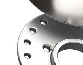
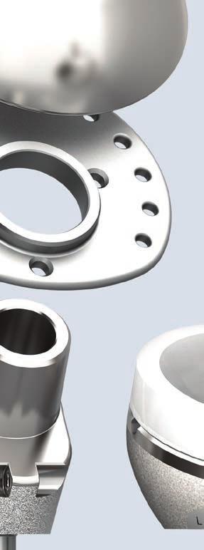
2 INTRODUCTION Introducing the GLOBAL UNITE Platform Shoulder Arthroplasty System, a modular shoulder system that provides surgeons principled adaptability within the Operating Room without compromising recognised biomechanical principles. Every shoulder fracture presents a unique challenge. That is why Depuy Synthes Joint Reconstruction has created GLOBAL UNITE, a next-generation platform system. The modular proximal bodies enable the surgeon to restore joint height in press-fit and cemented applications, whilst the modular suture collar facilitates anatomic reconstruction of the tuberosities. In the event that the patient s pathology indicates that a GLOBAL UNITE System conversion to a reverse shoulder is required, the conversion can be accommodated without compromising biomechanics. Removal of the proximal body makes provision for the epiphysis to be attached to a well-fixed distal stem within the humerus at the proper height and version to optimise deltoid function; as demonstrated by Professor Paul Grammont. 1 The GLOBAL UNITE System truly provides the surgeon Principled Adaptability within the Operating Room. Surgeon Support GLOBAL UNITE Surgeon Design Team: Anders Ekelund M.D. (SWEDEN) Joseph Iannotti M.D., PhD (USA) Laurent Lafosse M.D. (FRANCE) Ludwig Seebauer M.D. (GERMANY) Gerald R. Williams, Jr. M.D. (USA) Michael Wirth M.D. (USA) 2
3 TABLE OF CONTENTS Design Rationale Principled Adaptability 4 Surgical Technique Key Surgical Steps 6 Pre-operative Templating and Patient Positioning 8 Soft Tissue Dissection 9 Humeral Preparation 11 Trial Implantation and Tuberosity Reduction: Press-Fit Fixation 13 Trial Implantation and Tuberosity Reduction: Cemented Fixation 15 Humeral Shaft Preparation for Tuberosity Fixation 18 Final Stem and Proximal Component Assembly and Implantation 19 Final Tuberosity Attachment 22 Soft Tissue and Wound Closure 24 Conversion to DELTA XTEND Reverse Shoulder 25 Key Information Instrument Ordering Information 30 Implant Ordering Information 34 Essential Product Information and References 36 3


4 PRINCIPLED ADAPTABILITY Glenoid Components The GLOBAL UNITE System is also compatible with the following DePuy glenoid components 4


5 Humeral Heads Available in sizes mm in both standard and eccentric configurations Suture Collars Modular suture collar accommodates anatomic reconstruction of the tuberosities Proximal Bodies Multiple proximal body sizes and heights to accurately recreate the anatomy of the patient Principled Conversion to Reverse Convert to a DELTA XTEND Reverse Shoulder Arthroplasty System Stems Similar stem geometry to DELTA XTEND, stem does not require removal for conversion 5

")


6 KEY SURGICAL STEPS Remove Humeral Head and Tag Tuberosities Ream Humeral Canal Assemble Trial Components (Size 0 Body) Press-Fit Fixation Insert Implant and Impact Impact Collar Place Sutures Through Collar and Impact Head Insert Implant with Jig Cemented Fixation 6


7 Press-Fit Fixation Trial Insertion with Trial Inserter Attach Trial Collar Component and Reduce Tuberosities Create Final Construct Trial Insertion with Positioning Jig Cemented Fixation Suture Tuberosities Finished Tuberosity Reconstruction 7


.")
8 PRE-OPERATIVE TEMPLATING AND PATIENT POSITIONING Pre-operative Templating Pre-operative planning should be carried out using AP and Lateral shoulder radiographs of known magnification and the available GLOBAL UNITE Implant template to help the surgeon determine the size and alignment of the implant (Figure 1). The final decision should be made intraoperatively. Figure 1 Patient Positioning Place the patient in degree beach chair position. The knees should be flexed approximately 30 degrees and the involved shoulder should extend over the side of the surgical table (Figure 2). Some surgeons prefer to use an operating table specifically designed for shoulder surgery. Secure the patient s head (Figure 3). Use a drape to isolate the anaesthesia equipment from the sterile field. A sterile arm holder and positioning device can also be used. Figure 2 Figure 3 8
. It should follow the path of the cephalic vein along the interval between the deltoid and the pectoralis major.")
 for detailed information regarding exposure.")
9 SOFT TISSUE DISSECTION Deltopectoral Incision The initial incision line runs from the mid-clavicle, over the top of the coracoid and extends in a straight line down the anterior aspect of the arm (Figure 4). It should follow the path of the cephalic vein along the interval between the deltoid and the pectoralis major. The length of the initial incision along this line can be varied; depending on the exposure needed to provide adequate access and sight of the joint, and is determined by patient body habitus. Please refer to the GLOBAL ENABLE surgical technique ( ) for detailed information regarding exposure. Figure 4 Glenoid Exposure Simplified 9
10 SOFT TISSUE DISSECTION Releasing the Pectoralis Major Tendon and Clavipectoral Fascia Cut the upper portion of the pectoralis major tendon. Retract and separate the deltoid and pectoralis interval thereby defining the clavipectoral fascia. Divide the clavipectoral fascia just lateral to the conjoint tendon superiorly to the level of the coracoacromial ligament, which is preserved. Ligate or cauterise the anterior humeral circumflex vessels. Musculocutaneous Nerve Identification In fracture cases, it is important to identify and protect the musculocutaneous nerve. Palpate the musculocutaneous nerve as it comes from the brachial plexus into the posteriomedial aspect of the conjoint tendon. The nerve usually penetrates the muscle 2 to 5 cm inferior to the tip of the coracoid process. In some instances, the nerve has a higher penetration into the conjoint muscle tendon unit. Remember the nerve location when retracting the conjoint tendon. Greater and Lesser Tuberosity Identification The biceps tendon is an excellent landmark to identify the interval between the lesser and greater tuberosity. The fracture line in a four part fracture is usually lateral to the bicipital groove. Axillary Nerve Identification Place the arm in neutral abduction with internal rotation. Identify the upper border of the latissimus dorsi tendon and bluntly dissect above the tendon into the axillary pouch keeping the instrument on the inferior capsule. In most cases you can palpate the axillary nerve and then place a reverse Hohman retractor between the nerve and capsule to retract the nerve and protect it during inferior dissection of the capsule. 10


11 HUMERAL PREPARATION Stay Suture 2 Greater and Lesser Tuberosity Mobilisation Mobilise the greater and lesser tuberosities from adhesions and attached haematoma. Leave any capsule or healthy soft tissues attached to the proximal humerus. Pass #2 ORTHOCORD Sutures at the tendon bone interface as traction sutures. This step should result in normal mobility of these tissues (Figure 5). With the greater and lesser tuberosities mobilised and retracted out of the way by the stay sutures, use a clamp to retrieve the fractured humeral head. Remove any portion of articular humeral head that may remain on the tuberosity fragments. Open the sheath of the biceps tendon and divide the transverse humeral ligament. Remove the long head of the biceps and tenodese it distally to local soft tissue and resect the proximal portion to the superior glenoid tubercle. After removal of the biceps tendon examine the glenoid fossa for fracture or arthritic changes that may need to be surgically treated. Stay Suture 1 Figure 5 Removal and Sizing of the Head The selected humeral head component should be approximately 3 mm smaller in height than the resected humeral head because of the suture collar. The radius of curvature should be approximately the same. Assess the resected humeral head for height and diameter using the Humeral Head Template. The template takes into account the thickness of the prosthetic head and the suture collar; together these two components represent the volume of the native humeral head (Figure 6). Two styles of humeral head trials are available for the fracture set ranging from 12, 15,18 and 21mm heights and 40, 44, 48, 52 and 56mm diameters. After selecting the desired humeral head size, select the corresponding trial suture collar size. The selected head size and trial collar are colour coded and should match (Figure 7). Figure 6 52 x 15 mm Common Trial Humeral Head 52 mm Trial Suture Collar Figure 7 NOTE: The diameter of the suture collar must never be larger than the diameter of the head. 11
12 HUMERAL PREPARATION Cancellous Bone Removal After selecting the humeral head component, place the humeral head on the back table to be used later if necessary as a source of cancellous bone graft. Humeral Shaft Preparation Place the patient s arm in extension, adduction and external rotation. The arm and elbow should extend over the side of the table, which delivers the shaft out of the wound. Starting with a 6 mm reamer, sequentially ream the medullary canal to determine the humeral stem size (Figure 8). For standard length stems, ream to the largest size obtaining distal cortical contact such that the proximal edge of the cutting flutes reach the anatomic height of the detached greater tuberosity. For long stemmed implants, the reamers are advanced distally until the laser mark located superiorly on the reamer shaft reaches the same estimated level of the greater tuberosity. In some cases this level will need to be estimated by approximating the greater tuberosity to the proximal part of the humeral shaft fracture line or by measuring the height of the greater tuberosity fragment(s) with a ruler. Figure 8 12
 and distal stem wrench to connect the two components (Figure 9).")
.")
.")

13 TRIAL IMPLANTATION AND TUBEROSITY REDUCTION: PRESS-FIT FIXATION Press-Fit Trial Assembly and Positioning Assemble the selected stem with the corresponding proximal body size 0 trial. The stem and proximal component are colour coded. Use the female hex screwdriver (green handle) and distal stem wrench to connect the two components (Figure 9). Restoring Proper Retroversion and Height With the inserter, place the stem assembly into the intramedullary canal so that it is firmly fixed within the canal. The horseshoe collar of the stem inserter represents the final location of the suture collar and can be used as a reference to the medial calcar for the correct height placement (Figure 10). An alignment rod may be attached to the inserter at the desired retroversion. The alignment rod is inserted into the desired version hole on the inserter and is then aligned to the forearm (Figure 11). Native version varies within the normal population with an average retroversion of approximately 20 to 30 degrees with respect to the axis of the forearm when the elbow is in 90 degrees of flexion. Figure 9 Assemble the trial collar onto the epiphysis and reduce the greater tuberosity. The desired height of the stem is achieved when the greater tuberosity (supraspinatus rotator cuff insertion) is located under the collar and the distal portion of the tuberosity is anatomically reduced to the humeral shaft. Figure 10 If the stem is stable in the canal and the tuberosity is above the collar by 5 mm or more, the stem is too low. Remove the 0 mm proximal body component and attach the +5 mm proximal component. If the trial collar is still too low then trial a larger stem or use the positioning jig and use bone cement to place the originally selected stem at the desired height. Retroversion Alignment Figure 11 13


14 Press-Fit TRIAL IMPLANTATION AND TUBEROSITY REDUCTION: PRESS-FIT FIXATION Stem Height Adjustment If the trial stem and collar are too high, then remove the 0 mm proximal body and replace it with the 5 mm proximal body component. Minor corrections of 1-2 mm can be achieved by impacting the trial stem further into the humerus. If the trial collar is still too high, then downsize the stem and use the positioning jig and cement the stem (Figure 12) Proximal Body Sizes Figure Trial Reduction of Tuberosities After determining the correct implant sizing, height and version, reduce and hold the greater tuberosity in its anatomic position using the Greater Tuberosity Forceps provided in the instrument set (Figure 13). If the greater tuberosity is displaced away from the stem then remove some of the cancellous bone from the tuberosity. If the tuberosity is close to the stem but is not aligned with the edge of the centred suture collar, replace it with an eccentric collar and rotate it to optimise the alignment of the edge of the suture collar and the cuff insertion on the greater tuberosity. This should not result in an overhang of the collar with either of the tuberosities. Overhang can result in compromise or injury to the rotator cuff. If an eccentric collar is used then an eccentric head is also needed and positioned in the same orientation as the collar. Figure 13 Place the correct sized head (centred or eccentric) as determined by the sizing gauge onto the stem. Reduce the humeral head into the glenoid and bring the lesser tuberosity around the stem to check its position and tension (Figure 14). Check soft tissue tensioning by performing a gentle range of motion. Figure 14 It is recommended to perform an intra-operative x-ray or fluoroscopic examination to verify final prosthetic height and tuberosity position. The trial heads are barium infused and illuminate brightly under fluoroscopy. NOTE: There are no holes in the trial collar. Notches on the collar identify the hole locations of the final implant. 14
 and distal stem wrench to connect the two components.")

.")

15 TRIAL IMPLANTATION AND TUBEROSITY REDUCTION: CEMENTED FIXATION Cemented Trial Assembly and Positioning: Using a Positioning Jig Assemble the chosen stem with the corresponding proximal body size 0 trial. The stem and proximal component are colour coded. Use the female hex screwdriver (green handle) and distal stem wrench to connect the two components. Insert the trial stem using the inserter. The horse shoe collar of the stem inserter represents the final location of the suture collar and can be used as a reference to the medial calcar for the correct height placement. Use the positioning jig to then hold the trial stem in the desired position. Positioning Jig Loosely attach the positioning jig around the humeral shaft approximately 1 to 2cm distal to the fracture on the shaft (Figure 15). Align and attach the fin clamp to the anterior fin of the trial prosthesis assuring that the letter L or R is facing up denoting the side being operated upon (Figure 16). Rotate the stem and its attached positioning jig around the humeral shaft so that the alignment rod of the jig is in line with the forearm resulting in 30 degree retroversion of the stem to the forearm. Once the trial prosthesis is at the proper height and version, secure the positioning jig to the proximal humerus by tightening the large anterior screw using the 3.5 mm hex screwdriver (yellow handle) (Figure 17). Figure 15 Assemble the selected trial collar on the proximal body (Figure 18). Figure 16 Figure 17 15


16 Cemented TRIAL IMPLANTATION AND TUBEROSITY REDUCTION: CEMENTED FIXATION The positioning jig holds the trial implant securely to perform trial reduction and test the range of motion and stability. One of the most important advantages of the positioning jig is to make provision for reduction of the tuberosities. It also facilitates for range of motion testing with the trial prosthesis in place without a press fit stem. During range of motion testing, the trial implant should remain in the glenoid fossa and the head should not ride high in the glenoid. Adjust the stem height by sliding the fin clamp up or down the vertical height gauge so that the greater tuberosity is located under the collar and is reduced to the humeral shaft. To do this, use Greater Tuberosity Forceps provided in the instrument set or a towel clip to hold the greater tuberosities reduced around the prosthesis (Figure 19). Figure 18 Figure 19 16
17 TRIAL IMPLANTATION AND TUBEROSITY REDUCTION: CEMENTED FIXATION Cemented If the greater tuberosity is displaced away from the stem then remove some of the cancellous bone from the tuberosity. If the tuberosity is close to the stem but is not aligned with the edge of the centred suture collar replace it with an eccentric collar and rotate it to optimise the alignment of the edge of the suture collar and the cuff insertion on the greater tuberosity. This should not result in an overhang of the collar with either of the tuberosities. Overhang can result in compromise or injury to the rotator cuff. If an eccentric collar is used then an eccentric head is also needed and positioned in the same orientation as the collar. Place the correct sized head (centred or eccentric) as measured by the sizing gauge onto the stem (Figure 20). Reduce the humeral head into the glenoid and bring the lesser tuberosity around the stem to check its position and tension. Check soft tissue tensioning by performing a gentle range of motion. Figure 20 It is recommend to take an intra-operative x-ray or fluoroscopic examination to verify final prosthetic height and tuberosity position. The trial heads are barium infused and illuminate brightly under fluoroscopy. NOTE: There are no holes in the trial collar. Notches on the collar identify the hole locations of the final implant. 17

18 Cemented & Press-Fit HUMERAL SHAFT PREPARATION FOR TUBEROSITY FIXATION CEMENTED AND PRESS-FIT FIXATION Prior to removal of the stem for cemented or cementless technique note the position of the stem for version and height based upon bone landmarks on the proximal shaft. Mark the cortex with an electrocautery knife. Jig in Fixed Position For the cemented technique, loosen the anterior fin clamp from the anterior fin of the implant and leave the positioning jig in place. Be sure to check that it is securely attached to the shaft. Remove the trial implant from the humerus (Figure 21). Drill two suture holes through the anterior lateral portion of the shaft 2cm below the fracture line. Drill two suture holes through the posterior lateral portion of the shaft 2cm below the fracture line. Figure 21 Pass four strands of #2 ORTHOCORD Suture or larger nonabsorbable suture through the newly created holes. Both the anterior and posterior set of holes will have two sets of suture passing from inside the canal to the outside in a mattress suture technique. These will be used later as vertical suture fixation of the tuberosities (Figure 22). Figure 22 18
19 FINAL STEM AND PROXIMAL COMPONENT ASSEMBLY AND IMPLANTATION CEMENTED FIXATION Cemented Assemble the appropriate sized stem and proximal component with the female hex screwdriver (green handle) and the modular implant locking wrench (Figure 23). Place the implant into the impaction stand and impact the suture collar onto the neck in the intended position with the words Side Up facing up. Pass #2 ORTHOCORD Suture through the superior two holes of the suture collar to be used to reattach the supraspinatus and another #2 ORTHOCORD Suture through the suture collar more posterior to be used through infraspinatus. Two #2 ORTHOCORD Sutures are placed in the anterior portion of the collar for reattaching subscapularis (lesser tuberosity). All sutures should be placed so that the loose ends are exiting on the superior side of the collar creating a loop on the inferior side of the collar (Figure 24). Figure 23 Place a #2 ORTHOCORD Suture or larger non-absorbable suture through the medial hole of the proximal component of the assembled stem. When all sutures have been passed through the suture collar and implant, the humeral head can be impacted in the impaction stand or later when the stem has been implanted. Thoroughly irrigate the medullary canal to remove blood and other debris and dry the canal. Insert a cement restrictor distally to the final implant location to prevent migration of cement distally towards the elbow. Figure 24 19

20 Cemented FINAL STEM AND PROXIMAL BODY ASSEMBLY AND IMPLANTATION CEMENTED FIXATION Digitally insert bone cement such as DePuy SMARTSET GHV or HV Bone Cement into the medullary canal. If a cement gun is used, fill the canal from distal to proximal and avoid pressurisation that could fracture the humeral shaft. Insert the assembled final component into the cement to the height determined during the trialling process and hold in place via the positioning jig. With the positioning jig still in its original position secure the clamp to the anterior fin of the prosthesis to ensure that the final prosthetic is in the same position as the trial (Figure 25). Before the bone cement hardens, remove the excess to a level just below the proximal body portion of the stem. This will enable placement of cancellous bone material and easy exchange of the proximal body component if the stem height needs to be adjusted using the 0 or +5 component. In addition not cementing the proximal body component will aid in the removal of this part of the stem in the event of revision surgery for conversion to a reverse total shoulder. Figure 25 20
. Place the implant into the impaction stand and impact the suture collar onto the neck in the intended position with the words Side Up facing up.")
21 FINAL STEM AND PROXIMAL BODY ASSEMBLY AND IMPLANTATION PRESS-FIT FIXATION Press-Fit Assemble the appropriate sized stem and proximal body component with the female hex screwdriver (green handle) and the modular implant locking wrench (Figure 26). Place the implant into the impaction stand and impact the suture collar onto the neck in the intended position with the words Side Up facing up. Pass #2 ORTHOCORD Suture through the superior two holes of the suture collar to be used to re-attach the supraspinatus and second set of #2 ORTHOCORD Suture through the suture collar more posterior to be used through infraspinatus and two #2 ORTHOCORD Sutures are placed in the anterior portion of the collar for re-attaching subscapularis (lesser tuberosity). All sutures should be placed so that the loose ends are exiting the superior side of the collar creating a loop on the inferior side of the collar (Figure 27). Figure 26 Place a #2 ORTHOCORD Suture or larger non-absorbable suture through the medial hole of the proximal body component of the assemble stem. When all sutures have been passed through the suture collar and implant, the humeral head can be impacted in the impaction stand or later when the stem has been implanted. Implant the final construct into the humerus with the implant holder. Use the orientation pin placed into the proper alignment hole on the implant holder to assure that the implant is in the proper retroversion and impact the implant down to the proper height. Figure 27 21
. These two ends are clamped and tied later.")
 for the supraspinatus is placed from inside to out in the same fashion.")
22 FINAL TUBEROSITY ATTACHMENT Re-attaching the greater and lesser tuberosities to suture collar Pass the suture of the medial stem hole through the cuff insertion on the greater tuberosity from inside out, and one through the insertion point of the subscapularis also in an inside to out fashion (suture 1 & 2 of Figure 28). These two ends are clamped and tied later. Take posterior suture (E of Figure 29) in the collar and place it through the insertion of the infraspinatus from inside to out fashion. It is important to place the needle very close to the bone tendon junction. The superior suture (D of Figure 29) for the supraspinatus is placed from inside to out in the same fashion. Tie the superior suture first and then the posterior suture. Do not cut off the ends of the suture after tying. These sutures will be used for the vertical tension band repair. F D G E 1 2 B Figure 28 C Medial/Proximal Body Suture 22
.")
23 FINAL TUBEROSITY ATTACHMENT If the head has not been impacted, clean and dry the taper and assemble the head with the head impactor. The two anterior sutures are placed through the subscapularis tendon from an inside to out fashion close to the bone-tendon junction (F & G of Figure 29). To assure proper placement of the sutures a trial reduction should be performed and verified via fluoroscopy. Once verification has been achieved the sutures can be tied. The tuberosities are now attached to the suture collar. The loose ends of the two greater tuberosity sutures are tied to the lateral sutures in the humeral shaft in a vertical figure eight fashion. (D & E to C, Figure 30). This step will reduce the greater tuberosity into an anatomic position. The same process is performed with the sutures through the subscapularis (G & F to B, Figure 30) to create an anatomic reduction of the lesser tuberosity. These eight strands of suture create a tension band fixation of the tuberosities. The final step is to tie the horizontal sutures running through the medial hole of the implant (1 & 2) in a cerclage fashion to provide addition strength/stability to the tuberosity fixation. F D F D G E G E B C B C Figure 29 Figure 30 23
24 SOFT TISSUE AND WOUND CLOSURE Soft Tissue Closure Close the rotator interval between the subscapularis and the supraspinatus tendons. Wound Closure Thoroughly irrigate the wound with an antibiotic solution. Use a portable wound evacuation unit, such as the HEMO-DRAIN LC Wound Drainage System, to prevent formation of a postoperative hematoma. Infiltrate the soft tissues with 0.25 percent bupivacaine solution, which helps reduce immediate postoperative pain and facilitates passive shoulder motion on the same day as surgery. One option for wound closure is using a 2.0 VICRYL Suture in the deep subcutaneous layer, closing the skin with a running subcuticular nylon suture. If the posttraumatic skin is swollen and ecchymotic, interrupted skin sutures or skin clips may be preferred. After the dressing and shoulder immobiliser are in place, use a shoulder ice wrap. Place the prefrozen ice wrap on the shoulder in the operating room and replace it as needed. The combination of local anesthetic infiltration with bupivacaine injection and immediate cooling from the ice wrap markedly helps reduce postoperative pain. 24


 or the proximal component (collar).")
.")

 to unscrew the proximal bolt (Figure 32).")
25 CONVERSION TO DELTA XTEND REVERSE SHOULDER Removing the humeral head and proximal component Remove the head and suture collar using the head distractor. Remove each component (head, collar) independently from each other starting by removing the head first and then followed by the suture collar. Angle the head distractor so that both fingers of the instrument engage the collar (humeral head removal) or the proximal component (collar). This is important to assure that the appropriate mechanical forces are generated to remove the head and collar (Figure 31). Figure 31 Removing the Proximal Component Use appropriately sized thin osteotomes to remove the bone on-growth surrounding the proximal component. Once the fixation between bone and proximal component has been broken, use the female hex screwdriver (green handle) to unscrew the proximal bolt (Figure 32). Grasp the proximal component with a rongeur or similar device and remove it from the distal stem. Figure 32 25
.")
 Place the assembled reaming guide and orientation pin on the stem by aligning the pin to the forearm whilst keeping the reaming")

.")
26 CONVERSION TO DELTA XTEND REVERSE SHOULDER Humeral Reaming Position the orientation pin through the reaming guide at the desired reversed epiphysis version (Figure 33). (0 : reverse epiphysis will be parallel to the shoulder axis, non-anatomic version) (20 : reverse epiphysis will be 20 retroverted, anatomic version) Place the assembled reaming guide and orientation pin on the stem by aligning the pin to the forearm whilst keeping the reaming guide on the stem spigot (Figure 33). The maximum version range for the reverse epiphysis is +/-30, therefore it may not be possible to align the pin to the forearm for a stem positioned at more than 30 of version. If this is the case, we recommend using the maximum reaming guide position. Figure 33 Tighten the reaming guide screw to the stem using the 3.5 mm male hex screwdriver (yellow handle). Place the sizing guides on the reaming guide in order to determine the correct reverse epiphysis size. The correct size will be contained within the cortical wall (Figure 34). If the smaller size (size 1) is still out of the cortical wall, the version may need to be changed. Figure 34 26
.")

27 CONVERSION TO DELTA XTEND REVERSE SHOULDER Select the colour coded reamer (Red or Green) determined during the sizing exercise and prepare the humeral canal by using power (Figure 35). Once the reaming process has been completed the reamer guide can be removed with the 3.5 mm hex screwdriver (yellow handle). Use an osteotome or ronguers to remove any bone that may remain around the proximal portion of the distal stem that may prevent the proximal component from completely engaging with the stem (Figure 36). Figure 35 Figure 36 27

. Place the orientation guide pin through the retroversion hole that was originally determined during the reaming process (Figure 38).")
28 CONVERSION TO DELTA XTEND REVERSE SHOULDER Attaching the Trial Epiphysis Component to Distal Stem Attach the DELTA XTEND Trial Epiphysis to the reverse epiphysis holder by squeezing the distal portion and placing it within the epiphysis. Align the pins on the outside of the epiphyseal holder with the notches on the implant and release the holder, this will lock the two components together (Figure 37). Place the orientation guide pin through the retroversion hole that was originally determined during the reaming process (Figure 38). Align the trial epiphysis to the stem and align the pin to the forearm. Figure 37 Figure 38 28
 through the inner portion of the proximal holder and securely tighten the bolt. Remove the reverse epiphyseal holder when this step has been completed (Figure 39).")
29 CONVERSION TO DELTA XTEND REVERSE SHOULDER Once the component is in proper orientation, place the 3.5 mm hex screwdriver (yellow handle) through the inner portion of the proximal holder and securely tighten the bolt. Remove the reverse epiphyseal holder when this step has been completed (Figure 39). Remove any bone on the superior aspect of the trial epiphysis that could cause impingement. This can be down with an oscillating saw and using the trial epiphysis as a guide. Once the proximal component has been secured to the stem, all other steps of the procedure are consistent with DELTA XTEND Reverse Shoulder System. Please refer to DELTA XTEND Surgical Technique ( ) for the remaining portion of procedure. Figure 39 29


30 INSTRUMENT ORDERING INFORMATION GLOBAL UNITE System Common Case Top Tray Humeral Preparation Part Number Description Bullet Tip Reamer 6 mm Bullet Tip Reamer 7 mm Bullet Tip Reamer 8 mm Bullet Tip Reamer 9 mm Bullet Tip Reamer 10 mm Bullet Tip Reamer 11 mm Bullet Tip Reamer 12 mm Bullet Tip Reamer 13 mm Bullet Tip Reamer 14 mm Bullet Tip Reamer 15 mm Bullet Tip Reamer 16 mm Part Number Description Ratchet T-Handle Stem Wrench mm Stem Wrench mm Stem Wrench 6 8 mm Humeral Stem 6 mm Trial Humeral Stem 8 mm Trial Humeral Stem 10 mm Trial Humeral Stem 12 mm Trial Humeral Stem 14 mm Trial Humeral Stem 16 mm Trial 30

31 INSTRUMENT ORDERING INFORMATION GLOBAL UNITE System Common Case Bottom Tray Trial Heads Part Number Description mm Osteotomy Guide Pin Long mm Female Hex Screwdriver mm Hex Screwdriver Femoral/Humeral Head Impactor Impaction Stand Humeral Head 40 x 15 mm Trial Humeral Head 40 x 18 mm Trial Humeral Head 44 X 15 mm Trial Humeral Head 44 X 18 mm Trial Humeral Head 44 X 21 mm Trial Humeral Head 48 X 15 mm Trial Humeral Head 48 X 18 mm Trial Humeral Head 48 X 21 mm Trial Humeral Head 52 X 15 mm Trial Humeral Head 52 X 18 mm Trial Humeral Head 52 X 21 mm Trial Humeral Head 56 X 18 mm Trial Humeral Head 56 X 21 mm Trial Part Number Description Humeral Head 40 X 15 mm Eccentric Trial Humeral Head 40 X 18 mm Eccentric Trial Humeral Head 44 X 15 mm Eccentric Trial Humeral Head 44 X 18 mm Eccentric Trial Humeral Head 44 X 21 mm Eccentric Trial Humeral Head 48 X 15 mm Eccentric Trial Humeral Head 48 X 18 mm Eccentric Trial Humeral Head 48 X 21 mm Eccentric Trial Humeral Head 52 X 15 mm Eccentric Trial Humeral Head 52 X 18 mm Eccentric Trial Humeral Head 52 X 21 mm Eccentric Trial Humeral Head 56 X 18 mm Eccentric Trial Humeral Head 56 X 21 mm Eccentric Trial Common Trial Heads Part Number Description Common Humeral Head 40 X 12 Trial Common Humeral Head 40 X 15 Trial Common Humeral Head 40 X 18 Trial Common Humeral Head 44 X 12 Trial Common Humeral Head 44 X 15 Trial Common Humeral Head 44 X 18 Trial Common Humeral Head 44 X 21 Trial Common Humeral Head 48 X 15 Trial Common Humeral Head 48 X 18 Trial Common Humeral Head 48 X 21 Trial Common Humeral Head 52 X 15 Trial Common Humeral Head 52 X 18 Trial Common Humeral Head 52 X 21 Trial Common Humeral Head 56 X 18 Trial Common Humeral Head 56 X 21 Trial Common Humeral Head 40 X 15 Eccentric Trial Common Humeral Head 40 X 18 Eccentric Trial Common Humeral Head 44 X 15 Eccentric Trial Common Humeral Head 44 X 18 Eccentric Trial Common Humeral Head 44 X 21 Eccentric Trial Common Humeral Head 48 X 15 Eccentric Trial Common Humeral Head 48 X 18 Eccentric Trial Common Humeral Head 48 X 21 Eccentric Trial Common Humeral Head 52 X 15 Eccentric Trial Common Humeral Head 52 X 18 Eccentric Trial Common Humeral Head 52 X 21 Eccentric Trial Common Humeral Head 56 X 18 Eccentric Trial Common Humeral Head 56 X 21 Eccentric Trial 31
 Trial 2100-40-000 Proximal Body 12 (-5) Trial 2100-40-010 Proximal Body 12 (0) Trial 2100-40-020 Proximal Body 12 (+5) Trial 2100-50-000 Proximal Body 14 (-5) Trial 2100-50-010")

32 INSTRUMENT ORDERING INFORMATION GLOBAL UNITE System Fracture Case Top Tray Trials Part Number Description Proximal Body 10 (-5) Trial Proximal Body 10 (0) Trial Proximal Body 10 (+5) Trial Proximal Body 12 (-5) Trial Proximal Body 12 (0) Trial Proximal Body 12 (+5) Trial Proximal Body 14 (-5) Trial Proximal Body 14 (0) Trial Proximal Body 14 (+5) Trial Proximal Body 16 (-5) Trial Proximal Body 16 (0) Trial Proximal Body 16 (+5) Trial Suture Collar 40 mm Trial Suture Collar 44 mm Trial Suture Collar 48 mm Trial Suture Collar 52 mm Trial Suture Collar 56 mm Trial Long Humeral Stem 6 mm Trial Long Humeral Stem 8 mm Trial Long Humeral Stem 10 mm Trial Long Humeral Stem 12 mm Trial Suture Collar 40 mm Eccentric Trial Suture Collar 44 mm Eccentric Trial Suture Collar 48 mm Eccentric Trial Suture Collar 52 mm Eccentric Trial Suture Collar 56 mm Eccentric Trial Fracture Positioning Jig Bottom Tray - Instruments Part Number Description GLOBAL UNITE Head Gauge Implant Holder Collar Impactor Greater Tuberosity Forceps Humeral Head Distractor Extraction T-Handle 32

33 INSTRUMENT ORDERING INFORMATION GLOBAL UNITE System Revision Case Top Tray Part Number Description Epiphyseal Sizer Epiphyseal Sizer Epiphyseal Reamer Epiphyseal Reamer Epiphyseal Reamer Guide Reverse Epiphysis Holder Humeral Head Distractor Extraction T-Handle mm Osteotomy Guide Pin Long mm Female Hex Screwdriver Male Hex Screwdriver 33
34 IMPLANT ORDERING INFORMATION Standard Humeral Stem Components Part Number Description Standard Humeral Stem 6 mm x 83 mm Standard Humeral Stem 8 mm x 107 mm Standard Humeral Stem 10 mm x 113 mm Standard Humeral Stem 12 mm x 121 mm Standard Humeral Stem 14 mm x 130 mm Standard Humeral Stem 16 mm x 138 mm Humeral Long Stem Components Part Number Description Long Humeral Stem 6 mm x 143 mm Long Humeral Stem 8 mm X 177 mm Long Humeral Stem 10 mm X 183 mm Long Humeral Stem 12 mm X 191 mm Suture Collar Components Part Number Description Suture Collar 40 mm Suture Collar 44 mm Suture Collar 48 mm Suture Collar 52 mm Suture Collar 56 mm Suture Collar 40 mm Eccentric Suture Collar 44 mm Eccentric Suture Collar 48 mm Eccentric Suture Collar 52 mm Eccentric Suture Collar 56 mm Eccentric Proximal Bodies Part Number Description Proximal Body 10 (-5) Proximal Body 10 (0) Proximal Body 10 (+5) Proximal Body 12 (-5) Proximal Body 12 (0) Proximal Body 12 (+5) Proximal Body 14 (-5) Proximal Body 14 (0) Proximal Body 14 (+5) Proximal Body 16 (-5) Proximal Body 16 (0) Proximal Body 16 (+5) Humeral Head Components Part Number Description Humeral Head 40 x 15 mm Humeral Head 40 x 18 mm Humeral Head 44 x 15 mm Humeral Head 44 x 18 mm Humeral Head 44 x 21 mm Humeral Head 48 x 15 mm Humeral Head 48 x 18 mm Humeral Head 48 x 21 mm Humeral Head 52 x 15 mm Humeral Head 52 x 18 mm Humeral Head 52 x 21 mm Humeral Head 56 x 18 mm Humeral Head 56 x 21 mm Humeral Head 40 x 15 mm Eccentric Humeral Head 40 x 18 mm Eccentric Humeral Head 44 x 15 mm Eccentric Humeral Head 44 x 18 mm Eccentric Humeral Head 44 x 21 mm Eccentric Humeral Head 48 x 15 mm Eccentric Humeral Head 48 x 18 mm Eccentric Humeral Head 48 x 21 mm Eccentric Humeral Head 52 x 15 mm Eccentric Humeral Head 52 x 18 mm Eccentric Humeral Head 52 x 21 mm Eccentric Humeral Head 56 x 18 mm Eccentric Humeral Head 56 x 21 mm Eccentric DNI and Templates Part Number Description Humeral Stem DNI 10 mm Proximal Body DNI 10 (-5) Proximal Body DNI 10 (0) Proximal Body DNI 10 (+5) Humeral Head DNI 48 x 18 mm Suture Collar DNI 48 mm Humeral Head DNI 52 x 21 mm Eccentric Suture Collar DNI 52 mm Eccentric X-Ray Templates 34
35 IMPLANT ORDERING INFORMATION Metaglene Component Part Number Description Metaglene Glenosphere Component Part Number Description Glenosphere 38 mm Glenosphere 42 mm Glenosphere 38 mm Eccentric Glenosphere 42 mm Eccentric Metaglene Screw Components Part Number Description Non Locking Metaglene Screw 4.5 mm x 18 mm Non Locking Metaglene Screw 4.5 mm x 24 mm Non Locking Metaglene Screw 4.5 mm x 30 mm Non Locking Metaglene Screw 4.5 mm x 36 mm Non Locking Metaglene Screw 4.5 mm x 42 mm Locking Metaglene Screw 4.5 mm x 24 mm Locking Metaglene Screw 4.5 mm x 30 mm Locking Metaglene Screw 4.5 mm x 36 mm Locking Metaglene Screw 4.5 mm x 42 mm Locking Metaglene Screw 4.5 mm x 48 mm Polyethylene Cup and Humeral Spacer Part Number Description Humeral Polyethylene Cup 38 mm + 3 mm Humeral Polyethylene Cup 38 mm + 6 mm Humeral Polyethylene Cup 38 mm + 9 mm Humeral Polyethylene Cup 42 mm + 3 mm Humeral Polyethylene Cup 42 mm + 6 mm Humeral Polyethylene Cup 42 mm + 9 mm Humeral Polyethylene Cup 38 mm + 6 mm Retentive Humeral Polyethylene Cup 42 mm + 6 mm Retentive High Mobility Humeral Polyethylene Cup, Diameter 38 mm, +3 mm High Mobility Humeral Polyethylene Cup, Diameter 38 mm, +6 mm High Mobility Humeral Polyethylene Cup, Diameter 38 mm, +9 mm High Mobility Humeral Polyethylene Cup, Diameter 42 mm, +3 mm High Mobility Humeral Polyethylene Cup, Diameter 42 mm, +6 mm High Mobility Humeral Polyethylene Cup, Diameter 42 mm, +9 mm Humeral Spacer +9 mm 35
36 References 1. Boileau P, Watkinson DJ, Hatzidakis AM, Balg F. Grammont Reverse Prosthesis: Design Rationale and Biomechanics. J Shoulder Elbow Surg. 2005;14:S147-S161 The third party trademarks used herein are the trademarks of their respective owners. DePuy Orthopaedics EMEA is a trading division of DePuy International Limited. Registered Office: St. Anthony s Road, Leeds LS11 8DT, England Registered in England No DePuy France S.A.S. 7 Allée Irène Joliot Curie Saint Priest France Tel: +33 (0) Fax: +33 (0) DePuy Orthopaedics, Inc. 700 Orthopaedic Drive Warsaw, IN USA Tel: +1 (800) Fax: +1 (574) DePuy International Ltd St Anthony s Road Leeds LS11 8DT England Tel: +44 (0) Fax: +44 (0) depuysynthes.com DePuy International Ltd. and DePuy Orthopaedics, Inc All rights reserved. version 1 Revised: 06/13 CA#DPEM/ORT/1012/0283a
SURGICAL TECHNIQUE. Global Fx SHOULDER FRACTURE SYSTEM
 Global Fx SHOULDER FRACTURE SYSTEM TABLE OF CONTENTS Introduction................................................................. 2 System Highlights.....................................................
SURGICAL TECHNIQUE. Global Fx SHOULDER FRACTURE SYSTEM
 SURGICAL TECHNIQUE Global Fx SHOULDER FRACTURE SYSTEM TABLE OF CONTENTS Introduction................................................................. 2 System Highlights.....................................................
Design Rationale. The Design
 2 Table of Contents Design Rational...4 Introduction...6 System Highlights...7 Surgical Technique...10 Patient Positioning...10 Deltopectoral Incision...11 Releasing the Pectoralis Major Tendon and Clavipectoral
SURGICAL TECHNIQUE. Global Fx SHOULDER FRACTURE SYSTEM
 Global Fx SHOULDER FRACTURE SYSTEM TABLE OF CONTENTS Introduction................................................................. 2 System Highlights.....................................................
ANATOMICAL. REDEFINED.
 Operative Technique Fracture Stem Equinoxe Fracture Stem Operative Technique ANATOMICAL. REDEFINED. 352-377-1140 1-800-EXACTECH www.exac.com #718-00-33 REV A 0705 2005 EXACTECH, INC. ISO 13485 CERTIFIED
Anatomic and Reverse Shoulder. Surgical Technique
 Anatomic and Reverse Shoulder Surgical Technique CONTENTS KEY SURGICAL STEPS GLOBAL UNITE Platform Shoulder System Key Surgical Steps: Anatomic 4 GLOBAL UNITE Platform Shoulder System Key Surgical Steps:
The Bio-Modular Choice Shoulder System,
 Surgical Technique The Bio-Modular Choice Shoulder System, designed for both total and hemiarthroplasty of the shoulder, has enjoyed nearly two decades of clinical success. The variety of head types and
Solar Humeral Fracture System. Surgical Protocol
 Solar Humeral Fracture System Surgical Protocol Surgical Protocol Table of Contents Table of Contents Step By Step Procedure... 1 Patient Positioning... 3 Surgical Exposure... 4 Preparation of Humeral
TABLE OF CONTENTS SURGICAL TECHNIQUE 1 POST-OPERATIVE REHABILITATION 18. pages 1 RADIOLOGICAL ASSESSMENT 1 2 PATIENT POSITIONING 1
 TABLE OF CONTENTS SURGICAL TECHNIQUE 1 1 RADIOLOGICAL ASSESSMENT 1 2 PATIENT POSITIONING 1 3 DELTO-PECTORAL APPROACH 2 4 HUMERAL HEAD OSTEOTOMY 6 5 CHOICE OF HUMERAL INCLINATION AND RETROVERSION 7 pages
Anatomical Shoulder Fracture. Surgical Technique
 Anatomical Shoulder Fracture Surgical Technique Anatomical Shoulder Fracture Surgical Technique 3 Surgical Technique Anatomical Shoulder Fracture Table of Contents Indications 4 Preoperative Planning
Technique. Aequalis Resurfacing Humeral Head
 S u r g i c a l Technique Aequalis Resurfacing Humeral Head 1 The Aequalis Resurfacing Humeral Head has been developed in conjunction with Drew Miller, MD - Atlanta, GA. The Aequalis Resurfacing Humeral
URSA HEMI-SHOULDER ARTHROPLASTY B I O T E K
 URSA HEMI-SHOULDER ARTHROPLASTY SURGICAL TECHNIQUE B I O T E K 2 Surgical Position Once general anesthesia has been satisfactorily induced, or a supraclavicular nerve block has been given, the patient
This surgical technique describes how to perform an anatomic total shoulder arthroplasty implanting a short stem.
 INTRODUCTION This surgical technique describes how to perform an anatomic total shoulder arthroplasty implanting a short stem. CAUTION Federal law (USA) restricts this device to sale distribution and use
Fixed and Variable Geometry Total Shoulder Arthroplasty
 Fixed and Variable Geometry Total Shoulder Arthroplasty RECOVERY FUNCTION SURVIVORSHIP DePuy believes in an approach to total shoulder replacement that places equal importance on recovery, function and
DELTA XTEND. Reverse Shoulder System SURGICAL TECHNIQUE
 DELTA XTEND Reverse Shoulder System SURGICAL TECHNIQUE Described by Charles Neer in 1983, 1 the shoulder pathology known as Cuff Tear Arthropathy (CTA) has historically been seen as a significant surgical
DELTA XTEND. Reverse Shoulder System. Surgical Technique
 DELTA XTEND Reverse Shoulder System Surgical Technique Table of Contents DELTA XTEND System Key Surgical Steps 4 Pre-operative Templating and Patient Positioning 7 Surgical Approach 8 Intramedullary Canal
3. PATIENT POSITIONING & FRACTURE REDUCTION 3 8. DISTAL GUIDED LOCKING FOR PROXIMAL NAIL PROXIMAL LOCKING FOR LONG NAIL 13
 Contents IMPLANT FEATURES 2 1. INDICATIONS 3 2. PRE-OPERATIVE PLANNING 3 3. PATIENT POSITIONING & FRACTURE REDUCTION 3 4. INCISION 4 5. ENTRY POINT 4-6 6. PROXIMAL NAIL INSERTION 6-7 7. PROXIMAL LOCKING
AUTOBLOQUANTE AUTOBLOQUANTE. Product Rationale Surgical Technique
 AUTOBLOQUANTE AUTOBLOQUANTE Product Rationale Surgical Technique AUTOBLOQUANTE The Product of Long-Term Clinical Experience The AUTOBLOQUANTE femoral component is a direct descendant of the original straight
AcUMEDr. Locking Proximal Humeral Plate. PoLARUSr PHPt
 AcUMEDr Locking Proximal Humeral Plate PoLARUSr PHPt PoLARUSr PHPt LOCKING PROXIMAL HUMERAL PLATE Since 1988 Acumed has been designing solutions to the demanding situations facing orthopedic surgeons,
ANATOMIC SHOULDER ARTHROPLASTY
 ANATOMIC SHOULDER ARTHROPLASTY INTRODUCTION This surgical technique describes how to perform an anatomic shoulder arthroplasty implanting a cemented pegged glenoid baseplate. CAUTION Federal law (USA)
System. Humeral Nail. Surgical Technique
 System Humeral Nail Surgical Technique Contents IMPLANT FEATURES 2 1. INDICATIONS 3 2. PRE-OPERATIVE PLANNING 3 3. PATIENT POSITIONING & FRACTURE REDUCTION 3 4. INCISION 4 5. ENTRY POINT 4-6 6. PROXIMAL
TORNIER BIO-RSA. Bony Increased Offset - Reversed Shoulder Arthroplasty SURGICAL TECHNIQUE
 TORNIER BIO-RSA Bony Increased Offset - Reversed Shoulder Arthroplasty SURGICAL TECHNIQUE 2 Table of Contents: Concept...4 Bony Increased Offset Reversed Shoulder Arthroplasty (BIO-RSA ) Concept...4 Surgical
Conventus CAGE PH Surgical Techniques
 Conventus CAGE PH Surgical Techniques Conventus Orthopaedics The Conventus CAGE PH (PH Cage) is a permanent implant comprised of an expandable scaffold, made from nitinol and titanium, which is deployed
TEM TED S GRA INTE SHOULDER SY
 INTEGRATED S H O U L D E R S Y S T E M Humeral Stems Ream and trial surgical technique Cobalt chrome (with proximal porous coating available) Fixed head (Neer II and K-II-C) and modular options (Mod-II-C,
This publication is not intended for distribution in the USA.
 This publication is not intended for distribution in the USA. Extraction of a CORAIL Stem Surgical Technique Introduction Given the excellent long-term results of the CORAIL stem, 1,2,3 its extraction
Aequalis Press-Fit. Shoulder Prosthesis. Surgical Technique
 Aequalis Press-Fit Shoulder Prosthesis Surgical Technique SURGICAL TECHNIQUE RATIONALE OF THE AEQUALIS PRESS-FIT PROSTHESIS p. 1 THE AEQUALIS PRESS-FIT PROSTHESIS p. 2 SURGICAL TECHNIQUE p. 3-21 1. A detailed
Technique Guide. 3.5 mm LCP Periarticular Proximal Humerus Plate. Part of the Synthes locking compression plate (LCP) system.
 system.") Technique Guide 3.5 mm LCP Periarticular Proximal Humerus Plate. Part of the Synthes locking compression plate (LCP) system. Table of Contents Introduction 3.5 mm LCP Proximal Humerus Plate 2 AO Principles
Technique Guide 3.5 mm LCP Periarticular Proximal Humerus Plate. Part of the Synthes locking compression plate (LCP) system. Table of Contents Introduction 3.5 mm LCP Proximal Humerus Plate 2 AO Principles
Bone Preservation Stem
 TRI-LOCK Bone Preservation Stem Featuring GRIPTION Coating Surgical Technique Implant Geometry Extending the TRI-LOCK Stem heritage The original TRI-LOCK Stem was introduced in 1981. This implant was
S H O U L D E R Solutions by Tornier. BIO-RSA TM ANGled SURGICAL TECHNIQUE. BIO-RSA Angled. surgical technique
 S H O U L D E R Solutions by Tornier BIO-RSA TM ANGled SURGICAL TECHNIQUE BIO-RSA Angled Bony increased offset - reversed shoulder arthroplasty surgical technique BIO-RSA TM ANGled SURGICAL TECHNIQUE BIO-RSA
BICEPTOR Tenodesis System
 BICEPTOR Tenodesis System Sub-Pectoral Biceps Tenodesis A Shoulder Series Technique Guide As described by: Nikhil N. Verma, MD As described by: Nikhil N. Verma, MD Midwest Orthopedics at Rush Chicago,
REVERSE SHOULDER ARTHROPLASTY
 REVERSE SHOULDER ARTHROPLASTY 1 INTRODUCTION REVERSE SHOULDER ARTHROPLASTY This surgical technique describes how to perform a reverse total shoulder arthroplasty implanting a pegged glenoid baseplate.
Surgical Technique. Proximal Humerus Locking Plate
 Surgical Technique Proximal Humerus Locking Plate PERI-LOC Upper Extremity Locked Plating System 3.5mm & 4.5mm Proximal Humerus Locking PlatesCatalog Infor Table of Contents Introduction.........................................................2
Approach Patients with Confidence
 Approach Patients with Confidence The is the first stem specifically designed to be utilized with tissue sparing approaches, such as the anterior approach, as well as traditional approaches. The implant
SURGICAL TECHNIQUE DUAL-PLATFORM SHOULDER ARTHROPLASTY.
 SURGICAL TECHNIQUE DUAL-PLATFORM SHOULDER ARTHROPLASTY www.fhortho.com SURGICAL TECHNIQUE REFERENCE NUMBERS HUMERAL STEMS REFERENCE DIAMETER HEIGHT 267 360 Ø 06 100 265 102 Ø 08 120 265 103 Ø 08 170 265
Surgical. Technique. AEQUALIS Spherical Base Glenoid. Shoulder Prosthesis.
 Surgical Technique Shoulder Prosthesis AEQUALIS Spherical Base Glenoid www.tornier.com CONTENTS CONTENTS 1. Subscapularis 2. Anterior capsule 3. Humeral protector 4. Inserting retractors 1. DESIGN FEATURES
Surgical. Technique. Aequalis Press-Fit. Shoulder Prosthesis.
 Surgical Technique Shoulder Prosthesis www.tornier.com TABLE OF CONTENTS 1. Preoperative planning 2. Patient positioning 3. Delto-pectoral approach 4. Humeral head osteotomy 5. Reaming the humeral shaft
Approach Patients with Confidence
 Surgical Technique Approach Patients with Confidence The ACTIS Total Hip System is the first DePuy Synthes stem specifically designed to be utilized with tissue sparing approaches, such as the anterior
TORNIER AFFINITI EH 2. Extended Humeral Head SURGICAL TECHNIQUE
 TORNIER AFFINITI EH 2 Extended Humeral Head SURGICAL TECHNIQUE The AFFINITI Extended Humeral Head System was developed in collaboration with: John Brems, MD Cleveland, OH R. Sean Churchill, MD Milwaukee,
Clinical Evaluation Surgical Technique
 Clinical Evaluation Surgical Technique Table of Contents EMPERION Specifications 3 EMPERION Surgical Technique 9 EMPERION Catalog 18 Nota Bene: This technique description herein is made available to the
COMPLETE, CONVERTIBLE, INNOVATIVE. Surgical Technique REVERSE SHOULDER ARTHROPLASY
 COMPLETE, CONVERTIBLE, INNOVATIVE Surgical Technique Joint Spine Sports Med REVERSE SHOULDER ARTHROPLASY Reverse Shoulder Arthroplasty Surgical Technique 2 INDEX 1. INTRODUCTION 4 1.1 Indications of use
TM HUMELOCK II. Cemented. Hemi / Trauma. Total / Primary SURGICAL TECHNIQUE
 TM HUMELOCK II Cemented Hemi / Trauma SURGICAL TECHNIQUE Total / Primary CONTENTS - Surgical technique Humerus : Degenerative...page 0 - Surgical technique Glenoid...page 0 - Surgical technique Humerus
Open reduction; plate fixation 1 Principles
 Executive Editor: Peter Trafton Authors: Martin Jaeger, Frankie Leung, Wilson Li Proximal humerus 11-A2 Open reduction, plate fixation Search search... Shortcuts All Preparations All Approaches All Reductions
HUMELOCK II. Cemented + Graft ANATOMICAL and REVERSIBLE if REVISION SURGICAL TECHNIQUE
 TM HUMELOCK II Cemented + Graft ANATOMICAL and REVERSIBLE if REVISION SURGICAL TECHNIQUE CONTENTS - Device descriptionpage 02 - Intended use / indicationspage 03 - Warnings and precautions page 03 - Using
TORNIER AEQUALIS REVERSED FX. Shoulder System SURGICAL TECHNIQUE
 TORNIER AEQUALIS REVERSED FX Shoulder System SURGICAL TECHNIQUE 2 Table of Contents: Implant Description...4 Implant...6 Indications and Contraindications...6 Surgical Technique...7 Preoperative Planning...7
LAMINA SPREADER SURGICAL TECHNIQUE
 LAMINA SPREADER SURGICAL TECHNIQUE Balanced and appropriate external rotation of the femoral component is important for tibio-femoral stability in flexion and patello-femoral tracking/function. Depending
AcUMEDr. FoREARM ROD SYSTEM
 AcUMEDr FoREARM ROD SYSTEM FoREARM ROD SYSTEM Since 1988 Acumed has been designing solutions to the demanding situations facing orthopedic surgeons, hospitals and their patients. Our strategy has been
S h o u l d e r Solutions by Tornier C o n v e r T i b l e S h o u l d e r S y S T e m
 S h o u l d e r Solutions by Tornier C o n v e r t i b l e s h o u l d e r s y s t e m C o n v e r t i b l e s h o u l d e r s y s t e m A n a t o m i c Aequalis Ascend Flex - UDZF131 One System. Two Solutions.
Zimmer NexGen MIS Tibial Component. Cemented Surgical Technique IMAGE TO COME
 Zimmer NexGen MIS Tibial Component Cemented Surgical Technique IMAGE TO COME Zimmer NexGen MIS Tibial Component Cemented Surgical Technique 1 Zimmer NexGen MIS Tibial Component Cemented Surgical Technique
Operative Technique Resurfacing Humeral Head
 EXACTECH SHOULDER Operative Technique Resurfacing Humeral Head TABLE OF CONTENTS INTRODUCTION... 1 SYSTEM SPECIFICATIONS... 1 PATIENT POSITIONING... 2 SURGICAL APPROACH... 2 SIZING THE HUMERUS FOR A RESURFACING
SURGICAL TECHNIQUE. Alpine Cementless Hip Stem
 SURGICAL TECHNIQUE Alpine Cementless Hip Stem The following technique is a general guide for the instrumentation of the Alpine Cementless Hip Stem. It is expected that the surgeon is already familiar with
Solutions by Tornier. surgical technique
 S H O U L D E R Solutions by Tornier S I M P L I C I T I S U R G I C A L T E C H N I Q U E S H O U L D E R S Y S T E M surgical technique S I M P L I C I T I S H O U L D E R S Y S T E M S U R G I C A L
Distal Cut First Femoral Preparation
 Surgical Technique Distal Cut First Femoral Preparation Primary Total Knee Arthroplasty LEGION Total Knee System Femoral preparation Contents Introduction...3 DCF femoral highlights...4 Preoperative planning...6
Operative Technique. Platform Fracture Stem shoulder ANATOMICAL. REDEFINED.
 Operative Technique Platform Fracture Stem shoulder System ANATOMICAL. REDEFINED. TABLE OF CONTENTS INTRODUCTION... 1 SYSTEM SPECIFICATIONS... 2 hemiarthroplasty OVERVIEW TECHNIQUE... 4 Hemiarthroplasty
TRK REVISION KNEE Surgical Technique
 1 TRK REVISION KNEE Surgical Technique 1. 2. 3. 4. 5. 6. 7. 8. 9. 10. INTERCONDYLAR RESECTION...... page FEMORAL STEM...... page NON CEMENTED FEMORAL STEM...... page TRIAL FEMORAL COMPONENTS...... page
EXACTECH EXTREMITIES. Operative Technique. Preserve Stem. Surgeon focused. Patient driven. TM
 EXACTECH EXTREMITIES Operative Technique Preserve Stem Surgeon focused. Patient driven. TM TABLE OF CONTENTS INTRODUCTION...1 DETAILED OPERATIVE TECHNIQUE...2 PREOPERATIVE PLANNING/PATIENT POSITIONING...2
operative technique Kent Hip
 operative technique Kent Hip The Kent Hip Operative Technique The Kent Hip was developed by Mr Cliff Stossel, FRCS in Maidstone, Kent, UK and first implanted in 1986. It was designed to deal with problems
MIS Cemented Tibial Component
 MIS Cemented Tibial Component NexGen Complete Knee Solution Surgical Technique Table of Contents Surgical Exposure... 2 Finish the Tibia... 2 Position Based on Anatomic Landmarks... 3 Lateral Posterior
Olecranon Osteotomy Nail. For simple fractures and osteotomies of the olecranon.
 Olecranon Osteotomy Nail. For simple fractures and osteotomies of the olecranon. Technique Guide Discontinued June 2016; AVAILABLE FOR IMPLANT REMOVAL PURPOSES ONLY DSEM/TRM/0517/0843 Table of Contents
SHOULDER EXTRACTION INSTRUMENTS
 SHOULDER EXTRACTION INSTRUMENTS PRODUCT OVERVIEW Introducing the orthopaedic industry s first dedicated Shoulder Extraction Instrument set. DePuy Synthes Joint Reconstruction has created this set of instruments
Encina Taper Stem. Stinson Orthopedics Inc. 303 Twin Dolphin Drive, Suite 600 Redwood City, CA
 Stinson Orthopedics Inc. 303 Twin Dolphin Drive, Suite 600 Redwood City, CA 94065 info@stinsonortho.com www.stinsonortho.com Table of Contents Introduction 3 Features 4 Surgical Technique 5 Preoperative
Surgical Technique. Intramedullary locked Nailing With Screws for Humerus Fractures Solid/Cannulated. Humeral Interlocking Nail.
 Screws for Humerus Fractures Surgical Technique Humeral Interlocking Nail Approved by Humerus Nail Kit Code 08050001 Contents Introduction Implant design Indications Pre-operative planning Patient positioning
Comprehensive Fracture System. Surgical Technique
 Comprehensive Fracture System Surgical Technique 3 Comprehensive Fracture System Surgical Technique INDICATIONS 1. Non-inflammatory degenerative joint disease including osteoarthritis and avascular necrosis.
TORNIER SIMPLICITI. Shoulder System SURGICAL TECHNIQUE
 TORNIER SIMPLICITI Shoulder System SURGICAL TECHNIQUE Table of Contents: Indications & Contraindications... 4 System Compatibility & Pre-operative Planning... 4 Humeral Head Resection... 6 Freehand Resection
Modular Ulnar Head surgical technique. Transforming Extremities
 First Choice Modular Ulnar Head surgical technique Transforming Extremities instrumentation Head and Collar Trials Assembly Pad Starter Awl Trial Extractor Osteotomy Guide Stem Trials Implant Impactor
Comprehensive Fracture System. Surgical Technique
 Comprehensive Fracture System Surgical Technique 1 Comprehensive Fracture System Surgical Technique INDICATIONS 1. Non-inflammatory degenerative joint disease including osteoarthritis and avascular necrosis.
PIN GUIDE SYSTEM SURGICAL TECHNIQUE. with the SIGMA High Performance Instruments System. This publication is not intended for distribution in the USA.
 PIN GUIDE SYSTEM with the SIGMA High Performance Instruments System This publication is not intended for distribution in the USA. SURGICAL TECHNIQUE Pin Guide Surgical Technique The following steps are
Zimmer Periarticular Proximal Humeral Locking Plate
 Zimmer Periarticular Proximal Humeral Locking Plate Surgical Technique The Science of the Landscape Zimmer Periarticular Proximal Humeral Locking Plate 1 Surgical Technique Table of Contents Introduction
ANATOMIC SURGICAL TECHNIQUE. 5 in 1. Conventional instrumentation 07/11/2013
 ANATOMIC SURGICAL TECHNIQUE 5 in 1 Conventional instrumentation PRO.GB.933/1.0 Octobre 2013 2 Tibial step 3 Intramedullary technique - Based on the preoperative plan, drill the medullary canal with the
TM HUMELOCK II. Cementless. Hemi SURGICAL TECHNIQUE
 TM HUMELOCK II Cementless Hemi SURGICAL TECHNIQUE CONTENTS - Surgical technique...page 03 - Use of the OMS (Offset Modular System)...page 06 - Tuberosity synthesis...page 07 - Rehabilitation...page 07
RESURFACING HUMERAL HEAD IMPLANT TRAUMA & EXTREMITIES GROUP
 S U R G I C A L T E C H N I Q U E RESURFACING HUMERAL HEAD IMPLANT TRAUMA & EXTREMITIES GROUP TABLE OF CONTENTS SYSTEM OVERVIEW ANATOMIC SIZING AND DESIGN FEATURES INSTRUMENTATION INDICATIONS AND CONTRAINDICATIONS
Arthrex ECLIPSE Stemless Shoulder Prosthesis. Surgical Technique
 Arthrex ECLIPSE Stemless Shoulder Prosthesis Surgical Technique Content Introduction and Glenoid Options... 03 Humeral Preparation... 05 Humeral Implantation... 07 Wound Closure... 09 Postoperative Management...
Bigliani/Flatow The Complete Shoulder Solution TSA
 Bigliani/Flatow The Complete Shoulder Solution TSA Surgical Technique Replicates natural shoulder mobility, balance, and stability Bigliani/Flatow The Complete Shoulder Solution Surgical Technique 1 Bigliani/Flatow
SHOULDER ARTHROPLASTY SYSTEM
 SURGICAL TECHNIQUE SHOULDER ARTHROPLASTY SYSTEM COMBINING SCIENCE, SIMPLICITY AND CLINICAL SUCCESS Table of Contents Design Rationale................................1 The Glenoid.................................1
This publication is not intended for distribution in the USA. SURGICAL TECHNIQUE
 This publication is not intended for distribution in the USA. SURGICAL TECHNIQUE CONTENTS Introduction 2 Pre-operative Planning 4 Determining the Centre of Rotation 5 Surgical Technique 6 Acetabular Preparation
Pre-Operative Planning. Positioning of the Patient
 Surgical Technique Pre-Operative Planning Decide upon the size and angle of the barrel plate to be used from measuring the x-rays. To maximise the sliding action when using shorter lag screws, the Short
Surgical Technique. CONQUEST FN Femoral Neck Fracture System
 Surgical Technique CONQUEST FN Femoral Neck Fracture System Table of Contents Introduction... 3 Indications... 3 Product Overview... 4 Surgical Technique... 5 Patient Positioning... 5 Reduce the Fracture...
Surgical Technique. Forearm Fracture Solutions
 Surgical Technique Forearm Fracture Solutions Acumed is a global leader of innovative orthopaedic and medical solutions. We are dedicated to developing products, service methods, and approaches that improve
Restoring Anatomy SURGICAL TECHNIQUE
 Restoring Anatomy SURGICAL TECHNIQUE Welcome to the new Global AP (Adjustable Prosthesis) system. A system that has been developed by surgeons for surgeons by a world-leading design group including: Dr
Resurfacing Distal Femur. Orthopaedic Salvage System
 Resurfacing Distal Femur Orthopaedic Salvage System Primary Arthroplasty OSS 3cm Resurfacing Distal Femur Distal Femoral Resection Drill and ream the distal femur in the following sequence: (Figure 1)
the shape, the size, the fit Ascension Modular Radial Head
 the shape, the size, the fit Ascension Modular Radial Head WW anatomicdesign stem and head sizes to fit your indications and patient anatomy articular friendly shape reduces edge loading on the capitellum
PRODUCT RATIONALE & SURGICAL TECHNIQUE
 This publication is not intended for distribution in the USA. PRODUCT RATIONALE & SURGICAL TECHNIQUE THE PRODUCT OF LONG-TERM CLINICAL EXPERIENCE The TRILOC cemented UHMWPE cup is a direct descendant of
Percutaneous Humeral Fracture Repair Surgical Technique
 Percutaneous Humeral Fracture Repair Surgical Technique Percutaneous Pinning Percutaneous Humeral Fracture Repair Closed reduction followed by percutaneous fixation reduces risk from soft tissue dissection
AML Hip System. Design Rationale/ Surgical Technique
 AML Hip System Design Rationale/ Surgical Technique Design Rationale Evolution In 1977, DePuy Synthes Companies introduced the original cementless total hip. The AML Hip launched in order to solve one
RECLAIM REVISION SOLUTIONS
 RECLAIM REVISION SOLUTIONS Where Strength and Modularity Connect This publication is not intended for distribution in the USA. SURGICAL TECHNIQUE CONTENTS RECLAIM Modular Revision Hip System SURGICAL TECHNIQUE
ASHCOM Shoulder. Anatomical Shoulder Stems meet Comprehensive Reverse. Surgical Technique
 ASHCOM Shoulder Anatomical Shoulder Stems meet Comprehensive Reverse Surgical Technique Table of Contents Indications and Contraindications... 2 Surgical Technique Summary... 3 Humeral Head Resection...
Double Engine Orthopedic Bone Nail System Universal Humeral Nail
 Double Engine Orthopedic Bone Nail System ----------- Universal Humeral Nail Surgical Technique Manual Note: The surgical procedures should be performed under the guidance of qualified skilled orthopedic
Orthopedic Bone Nail System - Distal Femoral Nail Surgical Technique Manual
 Orthopedic Bone Nail System - Distal Femoral Nail Surgical Technique Manual Note: The surgical procedures should be performed under the guidance of qualified skilled orthopedic surgeons, and this surgical
AEQUALIS ADJUSTABLE REVERSED
 TORNIER AEQUALIS ADJUSTABLE REVERSED Shoulder System SURGICAL TECHNIQUE 2 Table of Contents: Indications/Contraindications...5 Pre-Operative Planning...6 Delto-Pectoral Humeral Exposure...7 Supero-Lateral
humerus InSafeLOCK Nail
 humerus InSafeLOCK Nail Introduction Content Humerus InSafeLOCK Nail is an innovative intramedullary nailing system, developed for humerus problems. Humerus fractures have 5-6 % incidence of all bone fractures.
GLENOID SURGICAL TECHNIQUE
 UP. EXTREMITY Dual-Platform Shoulder Prosthesis GLENOID SURGICAL TECHNIQUE ANATOMICAL REVERSE SURGICAL TECHNIQUE REFERENCE NUMBERS HUMERAL STEM REFERENCE DIAMETER HEIGHT 267 360 Ø 06 100 265 102 Ø 08 120
Operative Technique Resurfacing Humeral Head
 EXACTECH SHOULDER Operative Technique Resurfacing Humeral Head TABLE OF CONTENTS INTRODUCTION...1 RESURFACING HUMERAL HEAD...1 SYSTEM SPECIFICATIONS...1 DETAILED OPERATIVE TECHNIQUE...2 PATIENT POSITIONING...2
Technique Guide. Epoca Revision Instrument Set. For extraction and revision of Epoca shoulder implants.
 Technique Guide Epoca Revision Instrument Set. For extraction and revision of Epoca shoulder implants. Table of Contents Introduction Epoca Revision Instrument Set 2 Implantation of a Long or Extra-long
System Overview 3. Anatomic Sizing And Design Features 4. Instrumentation 6. Indications And Contraindications 7. Surgical Technique 8
 Surgical Technique Table of Contents System Overview 3 Anatomic Sizing And Design Features 4 Instrumentation 6 Indications And Contraindications 7 Surgical Technique 8 Implant Information 22 Instrumentation
Extramedullary Tibial Preparation
 Surgical Technique Extramedullary Tibial Preparation Primary Total Knee Arthroplasty LEGION Total Knee System Extramedullary tibial preparation Contents Introduction...2 EM tibial highlights...3 Preoperative
Index. B Backslap technique depth assessment, 82, 83 diaphysis distal trocar, 82 83
 Index A Acromial impingement, 75, 76 Aequalis intramedullary locking avascular necrosis, 95 central humeral head, 78, 80 clinical and functional outcomes, 95, 96 design, 77, 79 perioperative complications,
Optimum implant geometry
 Surgical Technique Optimum implant geometry Extending proven Tri-Lock heritage The original Tri-Lock was introduced in 1981. This implant was the first proximally coated tapered-wedge hip stem available
Anterior Approach Surgical Technique. Paragon Stem System. enabling people to enjoy life
 Anterior Approach Surgical Technique Paragon Stem System enabling people to enjoy life Contents Pre-Operative Planning... 2 Suggested Templating Method... 2 Surgical Technique... 3 Surgical Approach...
U2 PSA. Revision Knee. Surgical Protocol
 U2 PSA TM Revision Knee Surgical Protocol Table of Contents 1 Component Removal... 1 2 Tibial Preparation... 1 2.1 Tibial Canal Preparation... 1 2.2 Proximal Tibial Resection... 2 2.3 Non Offset Tibial
This publication is not intended for distribution in the USA. PRODUCT RATIONALE & SURGICAL TECHNIQUE
 This publication is not intended for distribution in the USA. PRODUCT RATIONALE & SURGICAL TECHNIQUE CONTENTS Design Rationale GLOBAL APG+ Instrument Design Rationale...2 Features and Benefits of Instruments...3