SURGICAL TECHNIQUE. Global Fx SHOULDER FRACTURE SYSTEM
|
|
|
- Andrea Lucas
- 5 years ago
- Views:
Transcription


1 Global Fx SHOULDER FRACTURE SYSTEM
2 TABLE OF CONTENTS Introduction System Highlights Surgical Technique Patient Positioning Deltopectoral Incision Releasing the Pectoralis Major Tendon and Clavipectoral Fascia Musculocutaneous Nerve Identification Greater and Lesser Tuberosity Identification Axillary Nerve Identification Humeral Head Excision and Measurement Cancellous Bone Removal Humeral Prosthesis Shaft Preparation Medullary Canal Reaming Lesser and Greater Tuberosity Mobilization Restoring Proper Humeral Length Proper Trial Prosthesis Positioning Restoring Proper Retroversion Global Fx Positioning Jig Fin Clamp Attachment Adjusting Humeral Retroversion Trial Reduction Trial Reduction of Tuberosities Around the Trial Prosthesis Modular Prosthesis Assembly Shaft Preparation Technique for Tuberosity Fixation Cementing the Prosthesis Removing Excess Cement Bone Graft Between the Prosthesis Collar and the Humeral Shaft Reattaching the Greater and Lesser Tuberosities to the Proximal Humeral Shaft Sutures from the Shaft to the Tuberosities Sutures Between the Tuberosities and Through the Anterior Fin Sutures From the Medial Fin Around Both Tuberosities Tying the Suture Fixation Rotator Interval Closure and Long Head Biceps Tenodesis Importance of Repairing the Tuberosities in Relationship to the Anterior Fin External Rotation Problem When Repairing Tuberosities to the Lateral Fin Wound Closure
3 INTRODUCTION Proximal humeral fractures are one of the most common indications for shoulder replacement. The Global Fx Shoulder Fracture System meets the unique challenges of prosthetic reconstruction of proximal humeral fractures previously unaddressed by earlier shoulder arthroplasty systems. 2 Greater tuberosity Humeral head Humeral shaft Lesser tuberosity Figure 1 Four-part proximal humeral fracture. The articular segment is a free fragment void of any soft tissue attachment or blood supply. The greater tuberosity is displaced superiorly and posteriorly by the pull of the attached rotator cuff while the lesser tuberosity is retracted medially by the pull of the subscapularis. The surgical neck of the humeral shaft is displaced medially by the pull of the pectoralis major. Managing proximal humeral fractures using a prosthesis is ordinarily indicated for patients over 59 years old with a four-part fracture (Figure 1), fracture dislocation or, in some cases, a threepart fracture (Figure 2) with osteopenia, comminution and generalized patient debilitation. In younger patients, surgeons may choose to treat the fracture with open reduction and internal fragment fixation or with an implant. Greater tuberosity Humeral shaft If an implant is chosen as treatment, the goals to be met are restoring proper mechanics, achieving adequate range of motion and eliminating patient discomfort. These goals can be met by selecting the proper humeral prosthesis height, establishing the desired humeral component retroversion and achieving anatomic and secure fixation of the tuberosities to each other and to the humeral shaft. Humeral head and and lesser lesser tuberosity Figure 2 Three-part greater tuberosity proximal humeral fracture. The articular segment is rotated internally by the pull of the subscapularis tendon attached to the lesser tuberosity. The greater tuberosity is displaced superiorly and posteriorly by the pull of the attached rotator cuff. The humeral shaft is displaced medially by the pull of the pectoralis major.

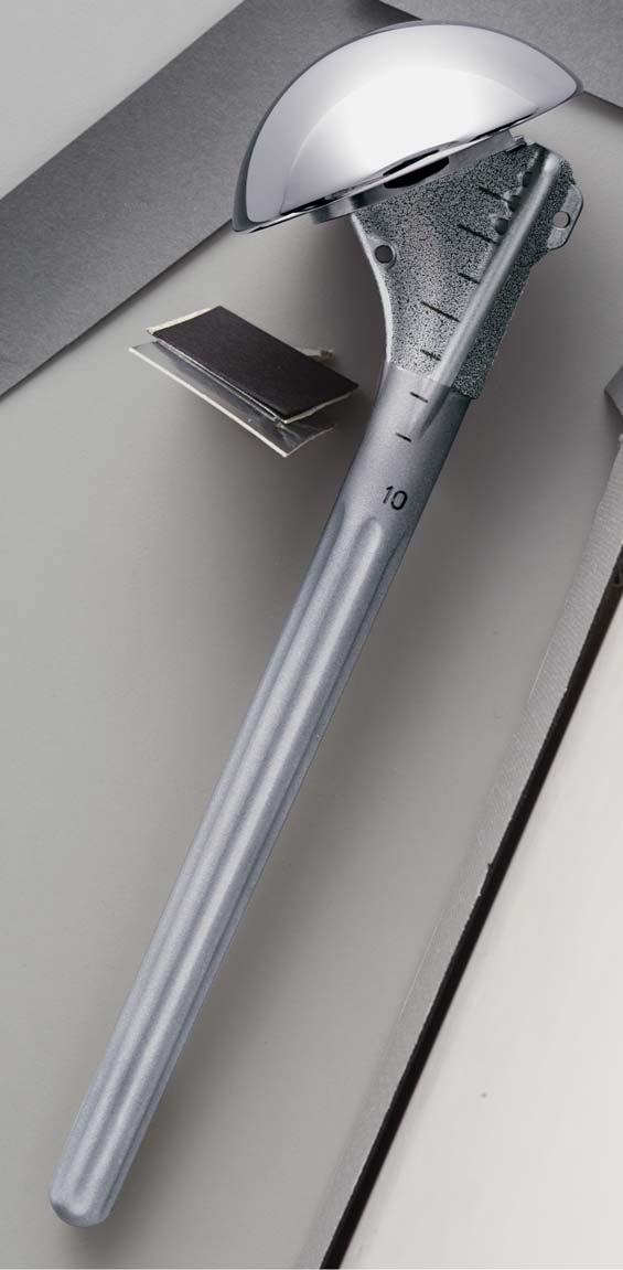
4 Minimal gap at taper Thin body Anterior fin Medial fin 5mm interval height markings Note Standard height lines Length Stem Note markings Neutral Align the rod rotation with the forearm Attach the rod to the tool Repair at Lesser anterior fin Greater 30 retroversion tuberosity Medial fin hole ADVANTAGE HEADS INTRODUCTION SYSTEM HIGHLIGHTS 2. The new head and collar design, 3a. Height indications on the humeral developed from an extensive stem and trials help improve height anthropometric study, increases assessment accuracy. articular surface area and improves joint biomechanics. 3c. Version of the prosthesis. 4. The anterior fin alignment provides a landmark for a more anatomic tuberosity reconstruction. 6. The new Advantage Heads are 7. A simplified instrumentation set is available in several diameters and contained in a single, compact case. head heights to assist in proper soft tissue balancing The reduced proximal humeral body helps preserve bone stock when reattaching the tuberosities. 3b. A Positioning Jig provides easier, more accurate height and version adjustments. R mm 48 mm 5. A medial hole in the body provides an additional point-of-suture fixation around the tuberosities. 52 mm
5 INTRODUCTION The Global Fx system is available in four body sizes (6, 8, 10 and 12mm) with standard and long stem lengths (Figures 3a and b). Modular head sizes are defined by the spherical diameter and head height and include the sizes noted in Figure 4. Stem Lengths Stem Length Body Size 6mm 8mm 10mm 12mm Std Length 120mm 130mm 140mm 150mm Long Length 160mm 200mm 210mm 220mm Figure 3a Global Fx standard length stem with an Advantage Humeral Head. Figure 3b Global Fx long stem with an Advantage Humeral Head. Global Advantage Humeral Head Sizes 15 mm Head Height 18 mm 21 mm Figure 4 44mm 48mm 52mm 4
6 INTRODUCTION As a result of designing the collar to recess into the humeral head underside, there is minimal articular gap between the assembled modular humeral head and stem components (Figure 5). This helps maximize the humeral articular surface area when reconstructing the humeral head anatomy. Figure 5 5
7 PATIENT POSITIONING Place the patient in a semi-fowler position (Figure 6a). Remove the table s standard headrest and replace it with a McConnell headrest, which allows free access to the shoulder s superior aspect. GLOBAL FX SHOULDER FRACTURE SYSTEM FOR PROXIMAL HUMERAL FRACTURES Charles A. Rockwood, Jr., MD, Frederick A. Matsen, III, MD and Steven B. Lippitt, MD Illustrations by Steven B. Lippitt, MD Position the patient so the involved shoulder extends over the top corner and edge of the table (Figures 6a and b). Figure 6a Patient positioning (side view) Figure 6b The involved shoulder should extend over the table edge. 6 Secure the patient s head with tape. Use a drape to isolate the anesthesia equipment from the sterile field.
8 DELTOPECTORAL INCISION Extend the incision from the distal clavicle across the coracoid process and down to the anterior aspect of the arm (Figure 7). Once the incision is made, locate the cephalic vein on the deltoid muscle near the deltopectoral interval Deltoid Cephalic vein Figure 8a Deltopectoral interval Gelpi retractor Gap between deltoid and pectoralis major Pectoralis major (Figure 8a). There is usually a gap superiorly between the deltoid and the pectoralis major muscles, and the pectoralis major muscle fibers are more horizontal than the deltoid fibers. Figure 7 Deltopectoral incision 7 Cephalic vein Deltoid To preserve the venous drainage of the deltoid muscle, retract the cephalic vein laterally with the deltoid muscle while developing the deltopectoral interval (Figure 8b). Cauterize or ligate the venous tributaries from the pectoralis major. Pectoralis major Figure 8b Retract the cephalic vein laterally to preserve the venous drainage of the deltoid muscle.
9 RELEASING THE PECTORALIS MAJOR TENDON AND CLAVIPECTORAL FASCIA Richardson retractor Cephalic vein 8 Protect the long head of the biceps Retract the deltoid and pectoralis major tendon with a retractor or finger while tendon to reveal the underlying releasing the upper portion of the clavipectoral fascia (Figure 9b). Divide pectoralis major tendon (Figure 9a). the clavipectoral fascia just lateral to the Releasing the tendon provides better conjoined tendon (dotted line) superiorly exposure of the joint s inferior to the level of the coracoacromial ligament, which is preserved. Conjoined tendon Clavipectoral fascia aspect. Deltoid Blunt elevator Figure 9a Release the upper portion of the pectoralis major tendon. Coracoacromial ligament Release upper pectoralis Release clavipectoral fascia Long head biceps Deltoid Figure 9b Divide the clavipectoral fascia lateral to the conjoined tendon (dotted line). Cephalic vein Coracoacromial ligament Conjoined tendon Released upper pectoralis
10 MUSCULOCUTANEOUS NERVE tendon (Figure 10). The nerve usually GREATER AND LESSER IDENTIFICATION TUBEROSITY IDENTIFICATION penetrates the muscle one to two inches In fracture cases, it is important to inferior to the tip of the coracoid The biceps tendon is an excellent identify and protect the process. In some instances, the nerve has landmark to identify the interval musculocutaneous nerve. Palpate the a higher penetration into the conjoined between the lesser and greater musculocutaneous nerve as it comes muscle tendon unit. Remember the tuberosity. Place a pair of scissors into from the brachial plexus into the nerve location when retracting the the sheath of the biceps tendon and posteromedial aspect of the conjoined conjoined tendon. divide the transverse humeral ligament. Continue proximally to open the rotator interval between the subscapularis and the supraspinatus tendons to the base of the coracoid process. Obtain retraction with the Hawkins-Bell Self-Retaining Coracoid Retractor (Figure 11) or Global Shoulder process Retractor System self-retaining frame. If Conjoined adequate assistance is available, use tendon Richardson retractors medially and laterally. Musculocutaneous nerve nerve Self-retaining retractor Figure 10 Palpate the musculocutaneous nerve beneath the conjoined tendon. Open rotator interval Biceps Figure 11 tendon Identify the long head of the biceps and release the transverse humeral ligament and rotator interval. 9
11 10 AXILLARY NERVE axillary nerve (Figure 12). Traction on HUMERAL HEAD EXCISION IDENTIFICATION the lesser tuberosity fragment will make AND MEASUREMENT Palpate the axillary nerve by passing the it easier to identify the axillary nerve. With the greater and lesser tuberosities volar surface of the index finger down Use a Scofield-type retractor to retract retracted out of the way by stay sutures, along the anterior surface of the and protect the nerve during inferior use a bone hook or clamp to retrieve the subscapularis muscle. Rotate and hook capsule fractured humeral head (Figure 13). the finger anteriorly to identify the Palpate axillary nerve release. Figure 12 Palpate the axillary nerve. Figure 13 Excise the fractured humeral head segment.
12 52 mm HUMERAL HEAD EXCISION AND MEASUREMENT (cont.) The selected humeral head component must approximate the resected humeral head height and radius of curvature Figure 14a Compare the humeral head component to the resected head s height and curvature. 48 mm Figure 14b Measure the resected humeral head height and diameter with the template to select the head component. (Figure 14a). Measure the resected Humeral Head trials for the fracture set humeral head for height and diameter range from 15, 18 and 21mm heights using the Humeral Head Template and 44, 48 and 52mm diameters (Figure (Figure 14b). The Global Advantage 4, pg. 4). ADVANTAGE HEADS mm
13 CANCELLOUS BONE REMOVAL the back table to remove the cancellous HUMERAL PROSTHESIS SHAFT PREPARATION bone (Figure 15). Use the cancellous graft After selecting the humeral head to help secure the tuberosity component, place the humeral head on Extend the arm off the side of the table, which delivers the shaft up and out of the wound. Use a rongeur to trim the sharp corners of the shaft (Figure 16). Remove bone fragments and blood clots from the humeral shaft canal. Figure 15 Obtain cancellous bone from the resected humeral head for later use as a bone graft. fixation. 12 Figure 16 Trim sharp corners from the surgical neck of the shaft.
14 MEDULLARY CANAL REAMING Ream the medullary canal if necessary to remove bony fragments and to determine a humeral body size. Four hand reamer sizes are available in 2mm increments from 6 to 12mm (Figure 17). The horizontal groove on the reamer identifies its use for the standard length and the end of the flute for the long stem prosthesis. The 10mm reamer fills the canal in Figure 17, suggesting that a 10mm standard length humeral body should be used. Length Long Standard Length Figure 17 Reaming the medullary canal helps determine the humeral body size. Long Length Standard Length
15 Free the lesser tuberosity from the Carefully identify and free the greater underlying soft tissues (Figure 18a). tuberosity in a similar manner (Figure Take care to protect the axillary nerve 18b). It is important to free and mobilize while mobilizing the lesser tuberosity the lesser and greater tuberosities so they and the attached subscapularis muscle can be attached to each other, around the tendon unit. prosthesis and back to the humeral upper shaft (Figure 18c). Freeing up the Figure 18b Freeing the greater tuberosity Greater tuberositylesser Figure 18c 14 LESSER AND GREATER TUBEROSITY MOBILIZATION greater tuberosity 18a Freeing the lesser tuberosityfigure
16 PROPER into the canal with the inferior aspect of HUMERAL LENGTH the head sitting on the humural proximal Attach the proper size trial head to a shaft (Figure 19a). With the arm held at small trial prosthesis, and place it into the patient s side, parallel to the floor the intramedullary canal. The body and in zero degrees of rotation (Figure should be small enough to allow passage 19b), apply gentle traction to the RESTORING arm. Zero degrees of rotation is most easily determined when the elbow is flexed 90 degrees and the forearm is pointed directly anterior (Figure 19c). While maintaining traction on the arm, use an instrument to lift the prosthesis head up to the level of the glenoid fossa. The prosthesis shaft has horizontal marks to determine how high the prosthesis should be when the head is adjacent to the glenoid fossa (Figure 19d). Figure 19a Figure 19b Note height lines Figure 19c Figure 19d 15
17 PROPER TRIAL PROSTHESIS POSITIONING Position the trial stem at the correct height to preserve space for anatomic below the collar and head of the prosthesis (Figures 20a and b). A slight overlap of the tuberosities on the shaft is desirable. reconstruction of the tuberosities 20a 20bFigure Placing the prosthesis too Placing the prosthesis at low does not allow space the correct height allows for anatomic reconstruction for anatomic of the tuberosities. reconstruction of the tuberosities. 16
18 RESTORING PROPER Typically, the anterior fin will be in line RETROVERSION or just medial to the old bicipital groove, While maintaining traction to hold the the biceps tendon and the insertion of prosthesis at the proper height, internally the pectoralis tendon on the humeral rotate the prosthesis until the head is anterior shaft. Make a notch on the directed into the glenoid fossa (Figure surgical neck of the shaft to mark this 21a). The usual amount of retroversion anterior fin position when the prosthesis will vary between degrees. is in the proper retroversion (Figures 21a b). and rotation atnotch anterior finneutral Figure 21a Notch or mark at Figure 21b the anterior fin. Rotate the prosthesis posteriorly to face the glenoid. 17
19 GLOBAL FX POSITIONING JIG humeral shaft clamp approximately 1 to by the notch on the shaft (Figure 22b). 2cm distal to the surgical neck fracture Once the trial prosthesis is properly Use the Global Fx Positioning Jig to of the shaft. Align the vertical height aligned, secure the Positioning Jig to the hold the prosthesis at the selected gauge to the anterior of the trial proximal humerus by tightening the height and retroversion during trial prosthesis, which was previously marked anterior screw (Figure 22c). reduction (Figure 22a). Attach the Align to notch at anterior fin Alignment Rod Fin Clamp Front View Top View Figure 22a The Global Fx Positioning Jig consists of a humeral shaft clamp and a connecting clamp Align to the notch 14 Tighten Tighten the clamp Clampon at anterior on 10 the the humeral Humeral shaftshaft cm Align Align to the tonotch Anterior and anterior Notch & Anterior Fin Figure 22b Figure 22c 18 R LT GT
20 FIN CLAMP ATTACHMENT Place the fin clamp (as oriented for the right or left shoulder) over the vertical height gauge of the humeral shaft clamp. Slide Fin Clamp over the Vertical Height Gauge Figure 22d Slide the fin clamp over the vertical height gauge Figure 22f R Secure the to the fin clamp to Anterior the anterior fin Fin Secure the fin clamp to the center of the relation to the shaft as previously three holes the anterior fin of the determined by the 5mm markings on the prosthesis by tightening the appropriate prosthesis body (Figure 19d, pg. 15). screw (Figures 22d and e). Place the Tighten the fin clamp to the vertical prosthesis at the appropriate height height gauge (Figures 22f and g). Tighten fin clamp to the anterior fin Figure 22e Tighten the fin clamp to the anterior fin. Figure 22g Tighten the fin clamp to the vertical height gauge. 19 R R
21 ADJUSTING HUMERAL RETROVERSION An Alignment Rod may be attached to the Global Fx Positioning Jig. If this rod is aligned with the forearm, the humeral Align the rod with the forearm R Attach the rod rod to the tool to retroversion Figure 23a prosthesis will automatically be in 30 degrees of retroversion (Figure 23a). Loosen the Positioning Jig on the shaft and internally rotate it to increase retroversion or rotate the jig externally to Figure 23b Ten degrees internal rotation of the jig on the shaft in relation to the forearm results in 40 degrees of retroversion retroversion decrease retroversion. For example, if 40 degrees of humeral retroversion is desired, internally rotate the jig 10 degrees (Figure 23b). 10 R
22 TRIAL REDUCTION prosthesis in place. During range of should not ride high in the glenoid. motion testing, the prosthesis should Motion should be free and easy without The Positioning Jig holds the prosthesis remain in the glenoid fossa and the head undue tightness. securely enough to perform trial reduction (Figure 24a) and test the range of motion and stability (Figures 24b and c). One of the most important alignment advantages of the Positioning Jig is that it allows range of motion testing with the trial Lesser tuberosityy Greater tuberosity Figure 24a Reduce the tubersosities around the Positioning Jig. Figure 24c The Positioning Jig allows testing of motion in forward elevation. Figure 24b The Positioning Jig allows testing of motion and stability in internal and external rotation. 21 R R R
23 TRIAL REDUCTION OF TUBEROSITIES AROUND THE TRIAL PROSTHESIS After determining and marking the proper height and rotation of the trial prosthesis using the fins and height lines, remove the jig and check the tuberosities again to see if they can be approximated around the prosthesis to one another and to the shaft (Figure 25a). Use reduction forceps or a towel clip to hold the tuberosities reduced around the prosthesis (Figure 25b). Check soft tissue tensioning by performing a gentle range of motion exercise. Figure 25a Figure 25b 22
24 MODULAR PROSTHESIS ASSEMBLY Place the Morse taper of the humeral head component on the humeral stem (Figure 26a). Place the stem in the assembly stand. Impact the humeral head component coaxial to the Morse taper to help ensure proper stability (Figure 26b). Make three to four blows with a two-pound mallet to secure the Morse taper. Figure 26a Figure 26b 23
25 SHAFT PREPARATION and out of these holes to anchor the CEMENTING THE PROSTHESIS TECHNIQUE FOR TUBEROSITY tuberosities back to the humeral shaft FIXATION Thoroughly irrigate the medullary canal (Figure 27b). Use the Dacron suture in to remove blood and other debris. Use a Drill holes in the proximal humeral shaft the anterior medial holes to secure the small, loose fitting piece of cancellous anterior medial, anterior lateral and lesser tuberosity; the suture in the lateral bone from the humeral head or direct anterior (Figure 27a). Use one or holes to secure the greater tuberosity and BIOSTOP two heavy nonabsorbable sutures, such G Resorbable Cement the suture in the anterior holes to secure Restrictor to help prevent excess cement as 1mm cotton Dacron tapes, passed in both tuberosities to the shaft (Figure 27b). from extending down to the elbow. Insert a vent tube down the medullary canal and push either a medium or high viscosity DePuy bone cement down into the upper humerus with finger pressure. The use of pressurized cement is not necessary and its use may produce a shaft fracture when the prosthesis is inserted (Figure 27c). Figure 27a Vent tube Bone cement Lateral suture Anterior Medial suture suture Cancellous bone plug Figure 27c setstwo of sutures (option) Figure 27b 24
26 REMOVING EXCESS CEMENT Dacron tape through the hole in the BONE GRAFT BETWEEN THE PROSTHESIS COLLAR AND medial fin. It will be used to pass around Insert the final stem by hand pressure THE HUMERAL SHAFT both tuberosities to help fixate them to and hold it at the proper height and the shaft and to each other. When the cement is set, place the version previously determined. Before autologous cancellous bone from the PMMA cement is set, remove the When seating the final prosthesis into the humeral head in the interval excess cement to just below the humeral cement, make sure it is at the same anteriorly and posteriorly between the shaft to allow room for placement of the height out of the canal as in the trial and humeral upper shaft and the prosthesis cancellous bone graft (Figure 27d). Pull that the anterior fin is lined up with the collar (Figure 27e). This additional the sutures back and forth to keep them humeral notch. If the trial measured helps ensure the healing of the mobile. Pass a strand or two of 1mm 25mm out of the shaft, then the final tuberosities to the shaft and to each prosthesis must be at the same position. other. Note that the anterior fin is lined up with the notch in the upper shaft. excessremove cement Suture through medial fincancellous bone graft Lateral suture Anterior Medial suture suture Figure 27d Figure 27e Remove the excess bone Place the cancellous bone cement at the shaft. graft around the prosthetic collar and the humeral shaft. 25
27 REATTACHING THE GREATER around the lesser and the SUTURES BETWEEN THE AND LESSER TUBEROSITIES TUBEROSITIES AND THROUGH anterior two sutures through or around both TO THE PROXIMAL HUMERAL THE ANTERIOR FIN SHAFT the greater and lesser tuberosities SUTURES FROM THE SHAFT respectively (Figure 28a). Since the sutures For additional fixation, pass sutures TO THE TUBEROSITIES may pull through the fragment between greater and lesser in osteoporatic bone, place sutures around tuberosities (Figure 28c). These sutures Pass the lateral two sutures of the shaft the tuberosity fragment and through the may anchored to anterior fin through or around the greater tuberosity. cuff tendons (Figure 28b). through the fin holes. It important Pass the medial two sutures through or to repair tuberosities to shaft and to each other in their normal anatomical position, which anterior in line with anterior fin of the prosthesis. Medial sutures Anterior sutures to the lesser tuberosity Lateral sutures to the greater tuberosity to both tuberosities Figure 28a Pass the sutures between the Sutures Through through the anterior fin fin shaft and the tuberosities. Sutures between the tuberosities Figure 28b Figure 28c For better fixation, pass the sutures Pass the sutures between the around the tuberosity and through the greater and lesser tuberosities tendon instead of through bone only. and the anterior fin. 26
28 SUTURES FROM THE MEDIAL FIN AROUND BOTH TUBEROSITIES hole For additional stability, pass one or two of the heavy, nonabsorbable 1mm tapes through the medial fin around both the greater and lesser tuberosities (Figure 28d). Pass Pass the suture through the medial fin the fin Medial fin 27 Figure 28d
29 28 TYING THE SUTURE FIXATION and the shaft and between the ROTATOR INTERVAL CLOSURE AND LONG HEAD BICEPS tuberosities to obtain firm fixation. Arm To help repair the tuberosities to each TENODESIS rotation and simultaneous movement of other, use a towel clip to hold them the tuberosities with the shaft should be Close the rotator interval between the together while tying the sutures (Figure possible, allowing early postoperative subscapularis and the supraspinatus 29a). It is important to place sufficiently rehabilitation. tendons. If tenodesis of the biceps is heavy sutures between the tuberosities anticipated, release the proximal segment from the glenoid and excise it (Figure 29b). Otherwise, a decrease in the shoulder s range of motion should be noted. Stabilize the tendon in the interval between the repaired lesser and greater tuberosities and incorporate it into the closure of the interval between the subscapularis and supraspinatus tendons. Tie securely Overlap the tuberosities with the shaft Figure 29a Figure 29b
30 Anterior fin at bicipital groove rotation Lesser tuberosity Greater tuberosity Neutral External rotation The Global Fx prosthesis has an anterior the humerus (Figure 30b). Anatomically fin, which should be lined up with the repair the lesser tuberosity medial to the old bicipital (Figure 30a). The and the greater tuberosity lateral repair of the two tuberosities together to this groove. This anatomical repair of this anterior fin landmark assures the the tuberosities allows for normal proper restoration of the tuberosities to external without restriction (Figure 30c). Neutral Repair Lesser anterior fin tuberosity Greater tuberosity Figure 30a Figure 30b position Neutral Figure 30c 29 IMPORTANCE OF REPAIRING THE TUBEROSITIES IN RELATIONSHIP TO THE ANTERIOR FIN
31 EXTERNAL ROTATION PROBLEM WHEN REPAIRING TUBEROSITIES TO THE LATERAL FIN The lateral fin of the prosthesis is often advocated as the reference for repairing the tuberosities (Figures 31a), which means that the arm must be internally rotated to repair the lesser tuberosity Similarly, the greater tuberosity and (Figure 31b). Repairing the tuberosities rotator cuff are not under enough to the lateral causes the lesser tension, which results nonanatomical tuberosity and the tendon restoration of the tuberosities and the to be under excessive tension, which overall loss of shoulder motion. restricts external rotation (Figure 31c). Internal rotation Suture through Tuberosities repaired lateral Lesser to lateral tuberosity Greater tuberosity Greater tuberosity fin Figure 31b Limited external rotation Neutral Tight subscapularis Figure 31a Neutral rotation Lesser tuberosity Figure 31c 30
32 WOUND CLOSURE Thoroughly irrigate the wound with an antibiotic solution. Use a portable wound evacuation unit, such as the Septer Closed Wound Drainage System, to prevent formation of a postoperative hematoma. Infiltrate the soft tissues with 0.25 percent Marcaine solution, which helps reduce immediate postoperative pain and facilitates passive shoulder motion on the same day as surgery (Figure 32). One option for wound closure is using a 2.0 Vicryl suture in the deep subcutaneous layer, closing the skin with a running subcuticular nylon suture (Figure 33). If the posttraumatic skin is swollen and ecchymotic, interrupted skin sutures or skin clips may be preferred. After the dressing and shoulder immobilizer are in place, use a shoulder ice wrap, such as the Dura*Kold Compression Ice Wrap System. Place the prefrozen ice wrap on the shoulder in the operating room and replace it with another unit every three hours. The combination of local anesthetic infiltration with Marcaine and immediate cooling from the ice wrap markedly helps reduce postoperative pain Figure 32 Figure 33 31


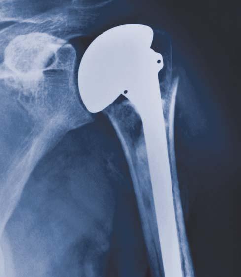
33 Global Fx - THE Shoulder Fracture System Postoperative Axillary/Lateral View Note the position of the lesser tuberosity. Postoperative Anterior/Posterior View Note the position of the greater tuberosity. 32
34 IMPORTANT This essential product information sheet does not include all of the information necessary for selection and use of a device. Please see full labeling for all necessary information. INDICATIONS Total shoulder or hemi-shoulder replacement is indicated for: 1. A severely painful and/or disabled joint resulting from osteoarthritis, traumatic arthritis or rheumatoid arthritis; 2. Fracture-dislocations of the proximal humerus where the articular surface is severely comminuted, separated from its blood supply or where the surgeon s experience indicates that alternative methods of treatment are unsatisfactory; 3. Other difficult clinical problems where shoulder arthrodesis or resection arthroplasty are not acceptable (e.g., revision of a failed primary component). Hemi-shoulder replacement is also indicated for: 1. Ununited humeral head fractures; 2. Avascular necrosis of the humeral head; 3. Rotator cuff tear arthropathy. Global CAP is indicated for intact or repairable rotator cuff. 4. Deformity and/or limited motion. Porocoat Porous-Coated Components: Porocoat porous-coated humeral stem prostheses are indicated for cemented or cementless use with fixation provided by biological tissue in-growth into the porous coating. Global CAP is intended for cementless use only. Cemented Components: Humeral stem and Glenoid components labeled For cemented use only are indicated only for use with bone cement. Press-fit or Cemented Components: Humeral stem prostheses without porous coating and labeled for press fit or cemented use only are indicated for press-fit uncemented use or for use with bone cement. CONTRAINDICATIONS The following conditions are contraindications for total shoulder and hemi-shoulder arthroplasty. 1. Active local or systemic infection. 2. Inadequate bone stock in the proximal humerus or glenoid fossa for supporting the components. 3. Poor bone quality, such as osteoporosis, where there could be considerable migration of the prosthesis and/or a chance of fracture of the humerus or glenoid. The following condition is a contraindication for total shoulder arthroplasty. 1. Absent, irreparable or nonfunctional rotator cuff or other essential muscles. WARNINGS AND PRECAUTIONS The use of a glenoid prosthesis in patients with cuff tear arthropathy could increase the risk of glenoid component loosening due to non anatomic loading conditions. The following conditions tend to adversely affect shoulder replacement implants: excessive patient weight, high levels of patient activity, likelihood of falls, poor bone stock, metabolic disorders, disabilities of other joints. ADVERSE EVENTS The following are the most frequent adverse events after shoulder arthroplasty: change in position of the components, loosening of components, dislocation, infection, hematoma, pneumonia, and cardiovascular disorders. Dura*Kold is a trademark of Dura*Kold Corporation. For more information about DePuy products, visit our web site at 3.5M (Rev. 4) Printed in USA DePuy Orthopaedics, Inc. All rights reserved.
SURGICAL TECHNIQUE. Global Fx SHOULDER FRACTURE SYSTEM
 Global Fx SHOULDER FRACTURE SYSTEM TABLE OF CONTENTS Introduction................................................................. 2 System Highlights.....................................................
SURGICAL TECHNIQUE. Global Fx SHOULDER FRACTURE SYSTEM
 SURGICAL TECHNIQUE Global Fx SHOULDER FRACTURE SYSTEM TABLE OF CONTENTS Introduction................................................................. 2 System Highlights.....................................................
Design Rationale. The Design
 2 Table of Contents Design Rational...4 Introduction...6 System Highlights...7 Surgical Technique...10 Patient Positioning...10 Deltopectoral Incision...11 Releasing the Pectoralis Major Tendon and Clavipectoral
DESIGN RATIONALE AND SURGICAL TECHNIQUE
 DESIGN RATIONALE AND SURGICAL TECHNIQUE ANCHOR PEG GLENOID DESIGN RATIONALE In total shoulder arthroplasty, most cases of clinical and radiographic loosening involve failure of the fixation of the glenoid
Solar Humeral Fracture System. Surgical Protocol
 Solar Humeral Fracture System Surgical Protocol Surgical Protocol Table of Contents Table of Contents Step By Step Procedure... 1 Patient Positioning... 3 Surgical Exposure... 4 Preparation of Humeral
ANATOMICAL. REDEFINED.
 Operative Technique Fracture Stem Equinoxe Fracture Stem Operative Technique ANATOMICAL. REDEFINED. 352-377-1140 1-800-EXACTECH www.exac.com #718-00-33 REV A 0705 2005 EXACTECH, INC. ISO 13485 CERTIFIED
This publication is not intended for distribution in the USA. PRODUCT RATIONALE & SURGICAL TECHNIQUE
 This publication is not intended for distribution in the USA. PRODUCT RATIONALE & SURGICAL TECHNIQUE INTRODUCTION Introducing the GLOBAL UNITE Platform Shoulder Arthroplasty System, a modular shoulder
System Overview 3. Anatomic Sizing And Design Features 4. Instrumentation 6. Indications And Contraindications 7. Surgical Technique 8
 Surgical Technique Table of Contents System Overview 3 Anatomic Sizing And Design Features 4 Instrumentation 6 Indications And Contraindications 7 Surgical Technique 8 Implant Information 22 Instrumentation
Integra. Titan Modular Shoulder System, 2.5
 Titan Modular Shoulder System, 2.5 Limit uncertainty with a shoulder implant system that redefines modularity, addresses multiple indications, and allows for reproducible results. Titan Modular Shoulder
Technique. Aequalis Resurfacing Humeral Head
 S u r g i c a l Technique Aequalis Resurfacing Humeral Head 1 The Aequalis Resurfacing Humeral Head has been developed in conjunction with Drew Miller, MD - Atlanta, GA. The Aequalis Resurfacing Humeral
URSA HEMI-SHOULDER ARTHROPLASTY B I O T E K
 URSA HEMI-SHOULDER ARTHROPLASTY SURGICAL TECHNIQUE B I O T E K 2 Surgical Position Once general anesthesia has been satisfactorily induced, or a supraclavicular nerve block has been given, the patient
The Bio-Modular Choice Shoulder System,
 Surgical Technique The Bio-Modular Choice Shoulder System, designed for both total and hemiarthroplasty of the shoulder, has enjoyed nearly two decades of clinical success. The variety of head types and
TABLE OF CONTENTS SURGICAL TECHNIQUE 1 POST-OPERATIVE REHABILITATION 18. pages 1 RADIOLOGICAL ASSESSMENT 1 2 PATIENT POSITIONING 1
 TABLE OF CONTENTS SURGICAL TECHNIQUE 1 1 RADIOLOGICAL ASSESSMENT 1 2 PATIENT POSITIONING 1 3 DELTO-PECTORAL APPROACH 2 4 HUMERAL HEAD OSTEOTOMY 6 5 CHOICE OF HUMERAL INCLINATION AND RETROVERSION 7 pages
Anatomical Shoulder Fracture. Surgical Technique
 Anatomical Shoulder Fracture Surgical Technique Anatomical Shoulder Fracture Surgical Technique 3 Surgical Technique Anatomical Shoulder Fracture Table of Contents Indications 4 Preoperative Planning
Operative Technique Resurfacing Humeral Head
 EXACTECH SHOULDER Operative Technique Resurfacing Humeral Head TABLE OF CONTENTS INTRODUCTION... 1 SYSTEM SPECIFICATIONS... 1 PATIENT POSITIONING... 2 SURGICAL APPROACH... 2 SIZING THE HUMERUS FOR A RESURFACING
Comprehensive Fracture System. Surgical Technique
 Comprehensive Fracture System Surgical Technique 3 Comprehensive Fracture System Surgical Technique INDICATIONS 1. Non-inflammatory degenerative joint disease including osteoarthritis and avascular necrosis.
RESURFACING HUMERAL HEAD IMPLANT TRAUMA & EXTREMITIES GROUP
 S U R G I C A L T E C H N I Q U E RESURFACING HUMERAL HEAD IMPLANT TRAUMA & EXTREMITIES GROUP TABLE OF CONTENTS SYSTEM OVERVIEW ANATOMIC SIZING AND DESIGN FEATURES INSTRUMENTATION INDICATIONS AND CONTRAINDICATIONS
Comprehensive Fracture System. Surgical Technique
 Comprehensive Fracture System Surgical Technique 1 Comprehensive Fracture System Surgical Technique INDICATIONS 1. Non-inflammatory degenerative joint disease including osteoarthritis and avascular necrosis.
TORNIER AFFINITI EH 2. Extended Humeral Head SURGICAL TECHNIQUE
 TORNIER AFFINITI EH 2 Extended Humeral Head SURGICAL TECHNIQUE The AFFINITI Extended Humeral Head System was developed in collaboration with: John Brems, MD Cleveland, OH R. Sean Churchill, MD Milwaukee,
This surgical technique describes how to perform an anatomic total shoulder arthroplasty implanting a short stem.
 INTRODUCTION This surgical technique describes how to perform an anatomic total shoulder arthroplasty implanting a short stem. CAUTION Federal law (USA) restricts this device to sale distribution and use
Surgical. Technique. AEQUALIS Spherical Base Glenoid. Shoulder Prosthesis.
 Surgical Technique Shoulder Prosthesis AEQUALIS Spherical Base Glenoid www.tornier.com CONTENTS CONTENTS 1. Subscapularis 2. Anterior capsule 3. Humeral protector 4. Inserting retractors 1. DESIGN FEATURES
TORNIER BIO-RSA. Bony Increased Offset - Reversed Shoulder Arthroplasty SURGICAL TECHNIQUE
 TORNIER BIO-RSA Bony Increased Offset - Reversed Shoulder Arthroplasty SURGICAL TECHNIQUE 2 Table of Contents: Concept...4 Bony Increased Offset Reversed Shoulder Arthroplasty (BIO-RSA ) Concept...4 Surgical
Open reduction; plate fixation 1 Principles
 Executive Editor: Peter Trafton Authors: Martin Jaeger, Frankie Leung, Wilson Li Proximal humerus 11-A2 Open reduction, plate fixation Search search... Shortcuts All Preparations All Approaches All Reductions
Operative Technique. Platform Fracture Stem shoulder ANATOMICAL. REDEFINED.
 Operative Technique Platform Fracture Stem shoulder System ANATOMICAL. REDEFINED. TABLE OF CONTENTS INTRODUCTION... 1 SYSTEM SPECIFICATIONS... 2 hemiarthroplasty OVERVIEW TECHNIQUE... 4 Hemiarthroplasty
TEM TED S GRA INTE SHOULDER SY
 INTEGRATED S H O U L D E R S Y S T E M Humeral Stems Ream and trial surgical technique Cobalt chrome (with proximal porous coating available) Fixed head (Neer II and K-II-C) and modular options (Mod-II-C,
SHOULDER ARTHROPLASTY SYSTEM
 SURGICAL TECHNIQUE SHOULDER ARTHROPLASTY SYSTEM COMBINING SCIENCE, SIMPLICITY AND CLINICAL SUCCESS Table of Contents Design Rationale................................1 The Glenoid.................................1
AcUMEDr. Locking Proximal Humeral Plate. PoLARUSr PHPt
 AcUMEDr Locking Proximal Humeral Plate PoLARUSr PHPt PoLARUSr PHPt LOCKING PROXIMAL HUMERAL PLATE Since 1988 Acumed has been designing solutions to the demanding situations facing orthopedic surgeons,
EXACTECH EXTREMITIES. Operative Technique. Preserve Stem. Surgeon focused. Patient driven. TM
 EXACTECH EXTREMITIES Operative Technique Preserve Stem Surgeon focused. Patient driven. TM TABLE OF CONTENTS INTRODUCTION...1 DETAILED OPERATIVE TECHNIQUE...2 PREOPERATIVE PLANNING/PATIENT POSITIONING...2
3. PATIENT POSITIONING & FRACTURE REDUCTION 3 8. DISTAL GUIDED LOCKING FOR PROXIMAL NAIL PROXIMAL LOCKING FOR LONG NAIL 13
 Contents IMPLANT FEATURES 2 1. INDICATIONS 3 2. PRE-OPERATIVE PLANNING 3 3. PATIENT POSITIONING & FRACTURE REDUCTION 3 4. INCISION 4 5. ENTRY POINT 4-6 6. PROXIMAL NAIL INSERTION 6-7 7. PROXIMAL LOCKING
Operative Technique Resurfacing Humeral Head
 EXACTECH SHOULDER Operative Technique Resurfacing Humeral Head TABLE OF CONTENTS INTRODUCTION...1 RESURFACING HUMERAL HEAD...1 SYSTEM SPECIFICATIONS...1 DETAILED OPERATIVE TECHNIQUE...2 PATIENT POSITIONING...2
Aequalis Press-Fit. Shoulder Prosthesis. Surgical Technique
 Aequalis Press-Fit Shoulder Prosthesis Surgical Technique SURGICAL TECHNIQUE RATIONALE OF THE AEQUALIS PRESS-FIT PROSTHESIS p. 1 THE AEQUALIS PRESS-FIT PROSTHESIS p. 2 SURGICAL TECHNIQUE p. 3-21 1. A detailed
Index. B Backslap technique depth assessment, 82, 83 diaphysis distal trocar, 82 83
 Index A Acromial impingement, 75, 76 Aequalis intramedullary locking avascular necrosis, 95 central humeral head, 78, 80 clinical and functional outcomes, 95, 96 design, 77, 79 perioperative complications,
System. Humeral Nail. Surgical Technique
 System Humeral Nail Surgical Technique Contents IMPLANT FEATURES 2 1. INDICATIONS 3 2. PRE-OPERATIVE PLANNING 3 3. PATIENT POSITIONING & FRACTURE REDUCTION 3 4. INCISION 4 5. ENTRY POINT 4-6 6. PROXIMAL
THE HUMERUS 20 THE HUMERUS* CROSS SECTION CROSS SECTION SUPERIOR VIEW
 20 THE HUMERUS* CROSS SECTION CROSS SECTION SUPERIOR VIEW The marrow canal of the humerus is funnel-shaped. Its successful pinning is influenced by many factors. With a few exceptions, the entire humerus
S H O U L D E R Solutions by Tornier. BIO-RSA TM ANGled SURGICAL TECHNIQUE. BIO-RSA Angled. surgical technique
 S H O U L D E R Solutions by Tornier BIO-RSA TM ANGled SURGICAL TECHNIQUE BIO-RSA Angled Bony increased offset - reversed shoulder arthroplasty surgical technique BIO-RSA TM ANGled SURGICAL TECHNIQUE BIO-RSA
ANATOMIC SHOULDER ARTHROPLASTY
 ANATOMIC SHOULDER ARTHROPLASTY INTRODUCTION This surgical technique describes how to perform an anatomic shoulder arthroplasty implanting a cemented pegged glenoid baseplate. CAUTION Federal law (USA)
Copeland/ Copeland EAS
 Copeland/ Copeland EAS Humeral Resurfacing Head Surgical Technique Table of Contents Patient Positioning and Approaches... 2 Copeland/Copeland EAS Humeral Resurfacing Head Surgical Technique Copeland
Operative Technique CTA Head
 EXACTECH SHOULDER Operative Technique CTA Head TABLE OF CONTENTS INTRODUCTION... 1 SYSTEM SPECIFICATIONS... 2 PRIMARY SHOULDER OPERATIVE TECHNIQUE OVERVIEW... 3 PRIMARY SHOULDER... 5 INDICATIONS FOR USE...
Arthrex ECLIPSE Stemless Shoulder Prosthesis. Surgical Technique
 Arthrex ECLIPSE Stemless Shoulder Prosthesis Surgical Technique Content Introduction and Glenoid Options... 03 Humeral Preparation... 05 Humeral Implantation... 07 Wound Closure... 09 Postoperative Management...
Surgical Technique. Proximal Humerus Locking Plate
 Surgical Technique Proximal Humerus Locking Plate PERI-LOC Upper Extremity Locked Plating System 3.5mm & 4.5mm Proximal Humerus Locking PlatesCatalog Infor Table of Contents Introduction.........................................................2
Anatomical Shoulder Glenoid. Surgical Technique
 Anatomical Shoulder Glenoid Surgical Technique Anatomical Shoulder Glenoid Surgical Technique 3 Table of Contents Glenoid Preparation Surgical Steps 4 Anatomical Shoulder Glenoid 4 Glenoid Components
D Degenerative joint disease, rotator cuff deficiency with, 149 Deltopectoral approach component removal with, 128
 Index A Abduction exercise, outpatient with, 193, 194 Acromioclavicular arthritis, with, 80 Acromiohumeral articulation, with, 149 Acromio-humeral interval (AHI), physical examination with, 9, 10 Active
BICEPTOR Tenodesis System
 BICEPTOR Tenodesis System Sub-Pectoral Biceps Tenodesis A Shoulder Series Technique Guide As described by: Nikhil N. Verma, MD As described by: Nikhil N. Verma, MD Midwest Orthopedics at Rush Chicago,
Surgical Technique. Intramedullary locked Nailing With Screws for Humerus Fractures Solid/Cannulated. Humeral Interlocking Nail.
 Screws for Humerus Fractures Surgical Technique Humeral Interlocking Nail Approved by Humerus Nail Kit Code 08050001 Contents Introduction Implant design Indications Pre-operative planning Patient positioning
Silicone PIP, MCP & MCP-X (PreFlex)
") Silicone PIP, MCP & MCP-X (PreFlex) Finger Joint Arthroplasty Operative Technique Silicone PIP Silicone MCP Silicone PreFlex (MCP-X) Stryker Disclaimer This publication sets forth detailed recommended
Silicone PIP, MCP & MCP-X (PreFlex) Finger Joint Arthroplasty Operative Technique Silicone PIP Silicone MCP Silicone PreFlex (MCP-X) Stryker Disclaimer This publication sets forth detailed recommended
Conventus CAGE PH Surgical Techniques
 Conventus CAGE PH Surgical Techniques Conventus Orthopaedics The Conventus CAGE PH (PH Cage) is a permanent implant comprised of an expandable scaffold, made from nitinol and titanium, which is deployed
Zimmer Trabecular Metal Ankle Interpositional Spacer and Trabecular Metal Ankle Fusion Spacer
 Zimmer Trabecular Metal Ankle Interpositional Spacer and Trabecular Metal Ankle Fusion Spacer Surgical Technique 2 Zimmer Trabecular Metal Ankle Interpositional Spacer and Trabecular Metal Ankle Fusion
Bigliani/Flatow The Complete Shoulder Solution TSA
 Bigliani/Flatow The Complete Shoulder Solution TSA Surgical Technique Replicates natural shoulder mobility, balance, and stability Bigliani/Flatow The Complete Shoulder Solution Surgical Technique 1 Bigliani/Flatow
Surgical. Technique. Aequalis Press-Fit. Shoulder Prosthesis.
 Surgical Technique Shoulder Prosthesis www.tornier.com TABLE OF CONTENTS 1. Preoperative planning 2. Patient positioning 3. Delto-pectoral approach 4. Humeral head osteotomy 5. Reaming the humeral shaft
Solutions by Tornier. surgical technique
 S H O U L D E R Solutions by Tornier S I M P L I C I T I S U R G I C A L T E C H N I Q U E S H O U L D E R S Y S T E M surgical technique S I M P L I C I T I S H O U L D E R S Y S T E M S U R G I C A L
TORNIER AEQUALIS REVERSED FX. Shoulder System SURGICAL TECHNIQUE
 TORNIER AEQUALIS REVERSED FX Shoulder System SURGICAL TECHNIQUE 2 Table of Contents: Implant Description...4 Implant...6 Indications and Contraindications...6 Surgical Technique...7 Preoperative Planning...7
Surgical Technique Guide PANTERA. Proximal Humerus Fracture Fixation Plate System
 Surgical Technique Guide PANTERA Proximal Humerus Fracture Fixation Plate System Installing the PANTERA is a 4-Step Process: The following technique is designed to optimize the surgical exercise. Step
Integra. Modular Radial Head System SURGICAL TECHNIQUE
 Integra Modular Radial Head System SURGICAL TECHNIQUE Table of Contents System Overview...2 Indications and Contraindications... 3 Modular Radial Head Implant Technique...4 Component Dimensions...8 Implant
Integra. Titan Total Shoulder System FRACTURE SURGICAL TECHNIQUE
 Integra Titan Total Shoulder System FRACTURE SURGICAL TECHNIQUE Table of Contents Design Rationale...02 Indications/Contraindication/Warnings/Precautions...03 Surgical Technique... 04 Step 1: Preoperative
TORNIER SIMPLICITI. Shoulder System SURGICAL TECHNIQUE
 TORNIER SIMPLICITI Shoulder System SURGICAL TECHNIQUE Table of Contents: Indications & Contraindications... 4 System Compatibility & Pre-operative Planning... 4 Humeral Head Resection... 6 Freehand Resection
comprehensive Design Rationale shoulder system Knees Hips Extremities Cement and Accessories PMI TEchnology
 comprehensive shoulder system Design Rationale Knees Hips Extremities Cement and Accessories PMI TEchnology . INTRODUCTION The Comprehensive Shoulder System is an evolutionary design based on the successful
CAUTION: Ceramic liners are not approved for use in the United States.
 Total Hip Prostheses, Self-Centering Hip Prostheses and Hemi-Hip Prostheses IMPORTANT: This essential product information sheet does not include all of the information necessary for selection and use of
SURGICAL TECHNIQUE CEMENTED & PRESS-FIT UNIFIED INSTRUMENTATION INTRAOPERATIVE FLEXIBILITY PROVEN BIOMECHANICS
 SURGICAL TECHNIQUE CEMENTED & PRESS-FIT UNIFIED INSTRUMENTATION INTRAOPERATIVE FLEXIBILITY PROVEN BIOMECHANICS INTRODUCTION The Summit Tapered Hip System s comprehensive set of implants and instruments
The NBX Non-Bridging External Fixator A Non-Bridging External Fixator/Locking Plate capturing a series of.062mm K-wires and 3mm half-pins that are
 The NBX Non-Bridging External Fixator A Non-Bridging External Fixator/Locking Plate capturing a series of.062mm K-wires and 3mm half-pins that are inserted in a multiplanar and multi-directional fashion
Proximal Humeral Fractures RSA v HHR. Proximal Humeral Fractures RSA v HHR. Introduction
 Proximal Humeral Fractures RSA v HHR Xavier A. Duralde, MD Peachtree Orthopaedic Clinic Atlanta, GA Proximal Humeral Fractures RSA v HHR Consultant: Smith+Nephew Board of Directors: CORR Introduction Incidence
TORNIER APPROACH. Shoulder Arthroplasty Program SURGICAL TECHNIQUE. Delivering efficiency & repeatability throughout the continuum of patient care
 TORNIER APPROACH Shoulder Arthroplasty Program SURGICAL TECHNIQUE Delivering efficiency & repeatability throughout the continuum of patient care 2 Table of Contents: APPROACH Program Overview...4 Instrument
HUMELOCK II. Cemented + Graft ANATOMICAL and REVERSIBLE if REVISION SURGICAL TECHNIQUE
 TM HUMELOCK II Cemented + Graft ANATOMICAL and REVERSIBLE if REVISION SURGICAL TECHNIQUE CONTENTS - Device descriptionpage 02 - Intended use / indicationspage 03 - Warnings and precautions page 03 - Using
Total Shoulder Arthroplasty
 1 Total Shoulder Arthroplasty Surgical indications and contraindications Anatomical Considerations: Total shoulder arthroplasty surgery involves the replacement of the humeral head and the glenoid articulating
Shoulder Joint Replacement
 Shoulder Joint Replacement Although shoulder joint replacement is less common than knee or hip replacement, it is just as successful in relieving joint pain. Shoulder replacement surgery was first performed
Encina Taper Stem. Stinson Orthopedics Inc. 303 Twin Dolphin Drive, Suite 600 Redwood City, CA
 Stinson Orthopedics Inc. 303 Twin Dolphin Drive, Suite 600 Redwood City, CA 94065 info@stinsonortho.com www.stinsonortho.com Table of Contents Introduction 3 Features 4 Surgical Technique 5 Preoperative
EXACTECH EXTREMITIES. Operative Technique. Platform Shoulder System. Surgeon focused. Patient driven. TM
 EXACTECH EXTREMITIES Operative Technique Platform Shoulder System Surgeon focused. Patient driven. TM TABLE OF CONTENTS EQUINOXE PLATFORM SHOULDER SYSTEM INTRODUCTION... 3 Primary Shoulder... 3 Reverse
Technique Guide. Primary Stemless Shoulder System
 Technique Guide TM Primary Stemless Shoulder System Anterior Deltopectoral Approach 1. Beachchair position (tilt back to 45 degree angle). 2. Short deltopectoral incision (from coracoid tip to pectoralis
ASHCOM Shoulder. Anatomical Shoulder Stems meet Comprehensive Reverse. Surgical Technique
 ASHCOM Shoulder Anatomical Shoulder Stems meet Comprehensive Reverse Surgical Technique Table of Contents Indications and Contraindications... 2 Surgical Technique Summary... 3 Humeral Head Resection...
Glenoid Resurfacing Technique Guide
 Glenoid Resurfacing Technique Guide Restoring the Freedom of Motion 2 Description The HemiCAP Contoured Articular Prosthetic humeral component incorporates an articular resurfacing component and a taper
Surgical Technique. Foundation Shoulder
 Surgical Technique Foundation Shoulder Foundation Shoulder Design Surgeon Richard J. Friedman, MD Professor of Orthopaedic Surgery Medical University of South Carolina Charleston, South Carolina DJO Surgical
S H O U L D E R Solutions by Tornier. Aequalistm. Pyrocarbon Humeral Head. surgical technique
 S H O U L D E R Solutions by Tornier Aequalis TM Pyrocarbon humeral head SURGICAL TECHNIQUE Aequalistm Pyrocarbon Humeral Head surgical technique Aequalis TM Pyrocarbon humeral head surgical TECHNIQUE
Operative Technique. Press-Fit. Anatomical. Redefined.
 Operative Technique Press-Fit Anatomical. Redefined. Table of Contents Introduction... 1 System Specifications... 2 Overview Technique... 3 detailed operative technique... 6 indications... 6 Pre-operative
SURGICAL TECHNIQUE GUIDE
 DANGER indicates an imminently hazardous situation which, if not avoided, will result in death or serious injury. WARNING indicates a potentially hazardous situation which, if not avoided, could result
REVERSE SHOULDER ARTHROPLASTY
 REVERSE SHOULDER ARTHROPLASTY 1 INTRODUCTION REVERSE SHOULDER ARTHROPLASTY This surgical technique describes how to perform a reverse total shoulder arthroplasty implanting a pegged glenoid baseplate.
the shape, the size, the fit Ascension Modular Radial Head
 the shape, the size, the fit Ascension Modular Radial Head WW anatomicdesign stem and head sizes to fit your indications and patient anatomy articular friendly shape reduces edge loading on the capitellum
COMPLETE, CONVERTIBLE, INNOVATIVE. Surgical Technique REVERSE SHOULDER ARTHROPLASY
 COMPLETE, CONVERTIBLE, INNOVATIVE Surgical Technique Joint Spine Sports Med REVERSE SHOULDER ARTHROPLASY Reverse Shoulder Arthroplasty Surgical Technique 2 INDEX 1. INTRODUCTION 4 1.1 Indications of use
SURGICAL TECHNIQUE DUAL-PLATFORM SHOULDER ARTHROPLASTY.
 SURGICAL TECHNIQUE DUAL-PLATFORM SHOULDER ARTHROPLASTY www.fhortho.com SURGICAL TECHNIQUE REFERENCE NUMBERS HUMERAL STEMS REFERENCE DIAMETER HEIGHT 267 360 Ø 06 100 265 102 Ø 08 120 265 103 Ø 08 170 265
Shoulder Arthroscopy Lab Manual
 Shoulder Arthroscopy Lab Manual Dalhousie University Orthopaedic Program May 5, 2017 Skills Centre OBJECTIVES 1. Demonstrate a competent understanding of the arthroscopic anatomy and biomechanics of the
Fixed and Variable Geometry Total Shoulder Arthroplasty
 Fixed and Variable Geometry Total Shoulder Arthroplasty RECOVERY FUNCTION SURVIVORSHIP DePuy believes in an approach to total shoulder replacement that places equal importance on recovery, function and
Turon Modular Shoulder System. Surgical Technique
 TM Turon Modular Shoulder System Surgical Technique DJO Surgical 9800 Metric Boulevard Austin, TX (800) 456-8696 www.djosurgical.com This brochure is presented to demonstrate a surgical technique. DJO
AEQUALIS ADJUSTABLE REVERSED
 TORNIER AEQUALIS ADJUSTABLE REVERSED Shoulder System SURGICAL TECHNIQUE 2 Table of Contents: Indications/Contraindications...5 Pre-Operative Planning...6 Delto-Pectoral Humeral Exposure...7 Supero-Lateral
DEVELOPED BY MEDSHAPE, INC. IN CONJUNCTION WITH PATRICK ST. PIERRE, M.D. BICEPS TENODESIS ARTHROSCOPIC AND SUBPECTORAL SURGICAL TECHNIQUE
 ! SURGICAL TECHNIQUE! DEVELOPED BY MEDSHAPE, INC. IN CONJUNCTION WITH PATRICK ST. PIERRE, M.D. ARTHROSCOPIC AND SUBPECTORAL BICEPS TENODESIS SURGICAL TECHNIQUE BICEPS TENODESIS Indications Tenodesis of
UDHT08.1.qxd:UDHT /03/08 17:14 Page 1. Surgical. Technique. Elbow Prosthesis. RHS Radial Head System.
 UDHT08.1.qxd:UDHT08.1 13/03/08 17:14 Page 1 Surgical Technique Elbow Prosthesis RHS Radial Head System www.tornier.com UDHT08.1.qxd:UDHT08.1 13/03/08 17:14 Page 2 TABLE OF CONTENTS DESIGN RATIONALE INDICATIONS
Zimmer NexGen MIS Tibial Component. Cemented Surgical Technique IMAGE TO COME
 Zimmer NexGen MIS Tibial Component Cemented Surgical Technique IMAGE TO COME Zimmer NexGen MIS Tibial Component Cemented Surgical Technique 1 Zimmer NexGen MIS Tibial Component Cemented Surgical Technique
Twin Tail TightRope System
 Open Stabilization of Acute Acromioclavicular Joint Dislocation using the Twin Tail TightRope System Surgical Technique Twin Tail TightRope System Open Stabilization of Acute Acromioclavicular Joint Dislocation
TM HUMELOCK II. Cemented. Hemi / Trauma. Total / Primary SURGICAL TECHNIQUE
 TM HUMELOCK II Cemented Hemi / Trauma SURGICAL TECHNIQUE Total / Primary CONTENTS - Surgical technique Humerus : Degenerative...page 0 - Surgical technique Glenoid...page 0 - Surgical technique Humerus
Optimum implant geometry
 Surgical Technique Optimum implant geometry Extending proven Tri-Lock heritage The original Tri-Lock was introduced in 1981. This implant was the first proximally coated tapered-wedge hip stem available
Restoring Anatomy SURGICAL TECHNIQUE
 Restoring Anatomy SURGICAL TECHNIQUE Welcome to the new Global AP (Adjustable Prosthesis) system. A system that has been developed by surgeons for surgeons by a world-leading design group including: Dr
Polarus 3 Solution Plates and Nails. Surgical Technique 4.3. Screws
 Polarus 3 Solution Plates and Nails Surgical Technique 4.3 mm Screws Acumed is a global leader of innovative orthopaedic and medical solutions. We are dedicated to developing products, service methods,
Surgical Technique. Cup System
 Surgical Technique Cup System INDICATIONS AND USAGE Indications for the use of the CS2 ACETABULAR CUP SYSTEM must be carefully considered with respect to the patient s entire evaluation and alternative
Technique Guide. VersiTomic G-Lok. J. Martin Leland III, M.D. Sub-Pectoral Proximal Biceps Tenodesis
 Technique Guide VersiTomic G-Lok Sub-Pectoral Proximal Biceps Tenodesis J. Martin Leland III, M.D. The opinions expressed are those of Dr. Leland and are not necessarily those of Stryker. Sub-Pectoral
AcUMEDr. FoREARM ROD SYSTEM
 AcUMEDr FoREARM ROD SYSTEM FoREARM ROD SYSTEM Since 1988 Acumed has been designing solutions to the demanding situations facing orthopedic surgeons, hospitals and their patients. Our strategy has been
MIS Cemented Tibial Component
 MIS Cemented Tibial Component NexGen Complete Knee Solution Surgical Technique Table of Contents Surgical Exposure... 2 Finish the Tibia... 2 Position Based on Anatomic Landmarks... 3 Lateral Posterior
BIOKNOTLESSRC ROTATOR CUFF REPAIR SUTURE ANCHOR SURGICAL TECHNIQUE. Surgical Technique for Arthroscopic Rotator Cuff Repair. Raymond Thal, M.D.
 SURGICAL TECHNIQUE ROTATOR CUFF REPAIR BIOKNOTLESSRC SUTURE ANCHOR Surgical Technique for Arthroscopic Rotator Cuff Repair Raymond Thal, M.D. Town Center Orthopaedic Associates Reston, Virginia Surgical
ReUnion. TSA Total Shoulder Arthroplasty System. Operative technique
 ReUnion TSA Total Shoulder Arthroplasty System Operative technique ReUnion TSA Shoulder System Operative technique ReUnion TSA Total Shoulder Arthroplasty System Surgical technique... 6 Patient positioning...
ReUnion. TSA Total Shoulder Arthroplasty System. Operative technique
 ReUnion TSA Total Shoulder Arthroplasty System Operative technique ReUnion TSA Shoulder System Operative technique ReUnion TSA Total Shoulder Arthroplasty System Surgical technique... 6 Patient positioning...
StageOne. Shoulder Cement Spacer Molds. Surgical Technique
 StageOne Shoulder Cement Spacer Molds Surgical Technique One Surgeon. One Patient. Over 1 million times per year, Biomet helps one surgeon provide personalized care to one patient. The science and art
AEQUALIS ASCEND TM FLEX
 TORNIER AEQUALIS ASCEND TM FLEX Convertible Shoulder System SURGICAL TECHNIQUE Tornier Upper Extremities Contents Chapter 1 4 Chapter 2 8 8 8 9 10 12 12 14 14 16 18 22 Chapter 3 23 23 23 24 25 25 26 26
Zimmer Trabecular Metal Glenoid
 Zimmer Trabecular Metal Glenoid Surgical Technique Interference fit for secure initial fixation Trabecular Metal Glenoid Surgical Technique 1 Table of Contents Glenoid Preparation 2 Determining the Size
Integra. Modular Radial Head System SURGICAL TECHNIQUE
 Integra Modular Radial Head System SURGICAL TECHNIQUE Table of Contents System Overview...2 Indications and Contraindications... 3 Modular Radial Head Implant Technique...4 Component Dimensions...8 Implant