As edited by Dr. Oheneba Boachie-Adjei, Dr. Matthew Cunningham, Dr. John Kostuik, Dr. Raymund Woo and the Complex Spine Study Group et al
|
|
|
- Jody Welch
- 6 years ago
- Views:
Transcription

1 As edited by Dr. Oheneba Boachie-Adjei, Dr. Matthew Cunningham, Dr. John Kostuik, Dr. Raymund Woo and the Complex Spine Study Group et al

2 RANGE Spinal System A fusion of DENALI and MESA, offering a complete array of unique screws, rod connectors, and hooks, coupled with exciting innovations in instrumentation, this comprehensive system is poised to address the entire range of complex spinal pathologies.
3 TABLE OF CONTENTS 1 NOTE: Instrumented levels are based on Surgeon preference and patient pathology. This methodology manual is intended to be used as a guideline for correction techniques with the RANGE Spinal System. Single Thoracic Exposure and Preparation 4 Screw Placement 4 Concave Left Rod Placement 4 Countertorsion 8 Thoracic Concave Translation 12 Convex Right Rod Placement 14 Final Deformity Correction 17 LIV Horizontalization 18 Additional Surgical Considerations 20 RANGE SPINAL SYSTEM Double Major Exposure and Preparation 24 Screw Placement 24 Concave Left Rod Placement 24 Countertorsion 26 Thoracic Translation 30 Convex Right Rod Placement 32 Lumbar Concave Translation 33 Final Deformity Correction 34 LIV Horizontalization 35 Additional Surgical Considerations 36 Thoracolumbar/Lumbar Exposure and Preparation 40 Screw Placement 40 Convex Left Rod Placement 40 Countertorsion 41 Concave Lumbar Translation 44 Final Deformity Correction 46 LIV Horizontalization 47 Additional Surgical Considerations 48 Kyphosis Initial Considerations 52 Screw Placement 52 Bilateral Rod Placement 53 Bilateral Compression T1-T2 (Proximal Foundation) 54 Sequential Bilateral Rod Introduction Into Deformity Crickets 56 Segmental Compression Toward Apical Vertebra 58 LIV Horizontalization 60 Additional Surgical Considerations 62 Glossary Implants 66 Instruments 67 Definitions 70
4
5 3 RANGE SPINAL SYSTEM Single Thoracic Right T4-L1 Exposure and Preparation Screw Placement Concave Left Rod Placement Countertorsion Thoracic Concave Translation Convex Right Rod Placement Final Deformity Correction LIV Horizontalization Additional Surgical Considerations


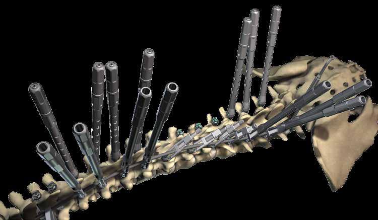
6 SINGLE THORACIC RIGHT T4-L NOTE: Instrumented levels are based on Surgeon preference and patient pathology. This methodology manual is intended to be used as a guideline for correction techniques with the RANGE Spinal System. Exposure and Preparation Perform facetectomies throughout. Screw Placement Use MESA Polyaxial Screws at the most proximal levels (T4 and T5) for ease of rod attachment and establishment of the proximal foundation. Otherwise, use MESA Uni-Planar or MESA 360 Screws throughout the spine. Confirm the screw heads are unlocked and all screws are at appropriate levels and aligned to accept the rod when applied. Concave Left Rod Placement Place Deformity Crickets on the concave side screws (3A). These will provide translation of screws and spine to the rod later. Pre-bend the rods in the physiological sagittal plane. For ease of rod insertion, place Deformity Crickets on only the upper half of the concave screws. After introducing rod, place Deformity Crickets over the lower half of the rod. Do not 3B


. This is preferably performed using the Rod Rotation")

7 5 tighten the Deformity Crickets, as they are only meant to ensure screw capture on the rod at this point. They will be used later for translation correction of the spine and reduction of the rods to the screws. RANGE SPINAL SYSTEM Rotate the rod into the sagittal plane (3B). This is preferably performed using the Rod Rotation Wrench and a Vise Grip. Seat the rod into the proximal fixation points T4 and T5 by tightening the Deformity Crickets (3C). 3A Continued on next page 3C 3C
8 SINGLE THORACIC RIGHT T4-L1 3E
.")
9 3 (CON T) Partially lock the T4 and T5 fixation points using the Superfly over the Deformity Crickets (3D). Fully lock the T4 and T5 fixation points with the Quick Locker to establish the proximal foundation of the deformity instrumentation (3E). The rod should be held in the physiological sagittal plane with the Rod Rotation Wrench or a Vise Grip. 7 RANGE SPINAL SYSTEM 3D
. The Manipulators on the convex screws aid in spine translation and partial derotation.")
10 SINGLE THORACIC RIGHT T4-L1 4 Countertorsion Apply Deformity Cricket Extenders on the concave side, and Manipulators to the convex apical screws to ease manipulation maneuvers during spinal vertebral derotation and translation (4A). The Manipulators on the convex screws aid in spine translation and partial derotation. During this maneuver, maintain countertorsion of the Lowest Instrumented Vertebra (LIV) to prevent en bloc rotation and coupling of the spine. 4A

11 9 RANGE SPINAL SYSTEM


12 SINGLE THORACIC RIGHT T4-L1 NOTE: When performing countertorsion, Transverse Couplers may be used on periapical vertebrae to facilitate rotational maneuvers (4B). 4B

13 11 RANGE SPINAL SYSTEM
14 SINGLE THORACIC RIGHT T4-L1 5 Thoracic Concave Translation Translation of the concave thoracic apex to the rod is performed by gradually tightening the Deformity Crickets from either end sequentially with progression toward the apex of the deformity (5A). By performing the translation simultaneously with several Deformity Crickets, the chance of screw pull-out and loss of fixation is reduced. The rod should be held in the physiological sagittal plane with the Rod Rotation Wrench or a Vise Grip. Once all Deformity Crickets are maximally tightened, the rod will be captured in each of the screw heads. Continued on next page

15 13 RANGE SPINAL SYSTEM 5A

16 SINGLE THORACIC RIGHT T4-L1 5 (CON T) 6 Partially lock all of the concave fixation points using the Superfly over the Deformity Crickets (5B). The Deformity Crickets may now be removed from the concave screws. Unlock all convex apical screws whose manipulators have been applied. Convex Right Rod Placement Place Deformity Crickets on the convex screws. The convex rod is introduced using the technique similar to the concave/corrective rod (6A). The proximal fixation points, T4 and T5, are partially locked using the Superfly over the Deformity Crickets and the rod is checked for proper sagittal plane alignment. Next, fully lock the T4 and T5 screws using the Quick Locker. The Deformity Crickets are then tightened sequentially to reduce the rod into the screws. Continued on next page 5B


17 15 RANGE SPINAL SYSTEM 6A


18 SINGLE THORACIC RIGHT T4-L1 6 (CON T) The Superfly is used to create a partial lock of each of the convex rod fixation points (6B). If necessary, the rod contour may be adjusted using the Medial/Lateral or In-situ Benders. 6B
19 7 Final Deformity Correction The final deformity correction is now performed using a variety of compression/ distraction and direct vertebral derotation (DVD) maneuvers. For compression/distraction, begin proximal to the apex. Compress or distract against a screw that has been buttressed with a DC Ring or a Vise Grip (7A & 7B). Remove the applied DC Rings. 17 RANGE SPINAL SYSTEM NOTE: The surgeon may also perform compression and/or distraction prior to partial locking by releasing the Deformity Cricket one to two turns to achieve final deformity correction. This method employs a similar technique to that of a standard set screw system. 7A 7B
. Transverse Connector(s) may be applied to the construct if indicated.")
20 SINGLE THORACIC RIGHT T4-L1 8 LIV Horizontalization Confirm horizontal position of the Lowest Instrumented Vertebra (LIV) and fully lock these fixation points using the Quick Locker. Repeat final locking of each screw with the Quick Locker to confirm rigid fixation throughout (8A). Transverse Connector(s) may be applied to the construct if indicated. Confirm at least 5 mm of rod length extends beyond the most proximal and distal screws. 8A
21 19 RANGE SPINAL SYSTEM
22 Additional Surgical Considerations Include: a. Do not attempt to forcefully derotate spine using the Deformity Crickets. The majority of the force should be applied to the Manipulators and rib hump on the convex side of the thoracic deformity, while simultaneously derotating the Deformity Crickets around the rod. b. Screws are more resistant to plowing through the pedicle during compression/ distraction maneuvers if the screw is moved caudally against the thicker bone of the caudal/foraminal aspect of the pedicle. c. Optional: In-situ bending of rod(s): i. Beginning at curve apex, Medial/Lateral Benders may be used to segmentally correct the deformity. ii. Minimize focal bending around a single screw to reduce the risk of bone failure. Placing Medial/ Lateral Benders around at least two screws is preferred. iii. The pear-shaped screwdriver handle can be placed between the pivot points of the Medial/Lateral Benders to improve leverage when bending across a long segment. d. For rigid deformities consider coronal bending of the concave rod at the apex while the rod is partially locked. Maintain final rod position with the coronal benders and simultaneously apply the Quick Locker to final lock the screws.
23 21 RANGE SPINAL SYSTEM
24
25 23 RANGE SPINAL SYSTEM Double Major T4-L3; Right Thoracic, Left Lumbar Exposure and Preparation Screw Placement Concave Left Rod Placement Coutertorsion Thoracic Translation Convex Right Rod Placement Lumbar Concave Translation Final Deformity Correction LIV Horizontalization Additional Surgical Considerations


26 DOUBLE MAJOR T 4 - L 3 R I G H T T H O R A C I C, L E F T L U M B A R NOTE: Instrumented levels are based on Surgeon preference and patient pathology. This methodology manual is intended to be used as a guideline for correction techniques with the RANGE Spinal System. Exposure and Preparation Perform facetectomies throughout. Screw Placement Use MESA Polyaxial Screws at the most proximal levels (T4 and T5) for ease of rod attachment and establishment of the proximal foundation. Otherwise, use MESA Uni-Planar or MESA 360 Screws throughout the spine. Confirm the screw heads are unlocked and all screws are at appropriate levels aligned to accept the rod when applied. Concave Left Rod Placement Place Deformity Crickets on the concave side screws (3A). These will provide translation of screws and spine to the rod later. Pre-bend the rods in the physiological sagittal plane. 3A 3B
27 25 For ease of rod insertion, place Deformity Crickets on only the upper half of the concave screws. After introducing rod, place Deformity Crickets over the lower half of the rod. Do not tighten the Deformity Crickets, as they are only meant to ensure screw capture on the rod at this point. They will be used later for translation correction of the spine and reduction of the rods to the screws. Rotate the rod into the sagittal plane (3B). This is preferably performed by using the Rod Rotation Wrench and a Vise Grip. Seat the rod into the proximal fixation points T4 and T5 by tightening the Deformity Crickets (3C). Continued on next page RANGE SPINAL SYSTEM 3C
.")

28 DOUBLE MAJOR T 4 - L 3 R I G H T T H O R A C I C, L E F T L U M B A R 3 (CON T) 4 Partially lock the T4 and T5 fixation points using the Superfly over the Deformity Crickets (3D). Fully lock the T4 and T5 fixation points with the Quick Locker to establish the proximal foundation of the deformity instrumentation (3E). The rod should be held in the physiological sagittal plane with a Rod Rotation Wrench or a Vice Grip. Maintain rod sagittal alignment with the Rod Rotation Wrench. Countertorsion Apply the Deformity Crickets and Cricket Extenders to the periapical concave thoracic and convex lumbar screws. Apply the Manipulators to the periapical convex thoracic and concave lumbar screws. This will ease manipulation maneuvers during spinal vertebral derotation and translation (4A). Advance Deformity Crickets to make contact with rods prior to Direct Vertebral Derotation. Simultaneous convex and concave direct vertebral derotation or countertorsion is carried out (4B). Continued on next page 3D 3E 4A

29 27 RANGE SPINAL SYSTEM 4B

30 DOUBLE MAJOR T 4 - L 3 R I G H T T H O R A C I C, L E F T L U M B A R (CON T) NOTE: When performing countertorsion, Transverse Couplers may be used on periapical vertebrae to facilitate rotational maneuvers (4C). 4C

31 29 RANGE SPINAL SYSTEM
.")
32 DOUBLE MAJOR T 4 - L 3 R I G H T T H O R A C I C, L E F T L U M B A R 5 Thoracic Translation Translation of the concave thoracic and convex lumbar apices to the rod is performed gradually by tightening the Deformity Crickets from either end sequentially with progression toward the apex of the deformity (5A). By performing the translation simultaneously with several Deformity Crickets, the chance of screw pull-out and loss of fixation is reduced. The rod should be held in the physiological sagittal plane with the Rod Rotation Wrench or a Vise Grip. Once all of the Deformity Crickets are maximally tightened, the rod will be captured in each of the screw heads. 5A

33 31 Partially lock all fixation points on the left rod using the Superfly over the Deformity Crickets (5B). The Deformity Crickets may now be removed from the left side. Unlock all apical screws whose Manipulators have been applied. Place Deformity Crickets on the right side. RANGE SPINAL SYSTEM 5B

.")

.")
34 DOUBLE MAJOR T 4 - L 3 R I G H T T H O R A C I C, L E F T L U M B A R 6 Convex Right Rod Placement The convex right rod is introduced using the technique similar to the concave/ corrective rod (6A). The proximal fixation points, T4 and T5, are partially locked using the Superfly over the Deformity Crickets and the rod is checked for proper sagittal plane alignment (6B). Next, fully lock the T4 and T5 screws using the Quick Locker (6C). 6A 6B 6C
. If necessary, the rod contour may be adjusted using the Medial/Lateral or In-situ Benders.")
35 7 Lumbar Concave Translation The Deformity Crickets are then tightened sequentially to reduce the rod into the screw and the Superfly is used to create a partial lock of each of the convex rod fixation points (7A). If necessary, the rod contour may be adjusted using the Medial/Lateral or In-situ Benders. 33 RANGE SPINAL SYSTEM 7A


36 DOUBLE MAJOR T 4 - L 3 R I G H T T H O R A C I C, L E F T L U M B A R 8 Final Deformity Correction The final deformity correction is now performed using a variety of compression/ distraction and direct vertebral derotation (DVD) maneuvers. For compressions/distraction maneuvers, begin with compression of the convex lumbar apex to the Lowest Instrumented Vertebra (LIV). Next, begin compression of the convex thoracic apex. Finally, perform distraction on the concave lumbar apex to achieve horizontalization of the LIV. Compress or distract against a screw that has been buttressed with a DC Ring or a Vise Grip (8A & 8B). Remove the applied DC Rings. NOTE: The surgeon may also perform compression and/or distraction prior to partial locking by releasing the Deformity Cricket one to two turns to achieve final deformity correction. This method employs a similar technique to that of a standard set screw system. 8A 8B
37 9 LIV Horizontalization Confirm horizontal position of Lowest Instrumented Vertebra (LIV) and fully lock these fixation points using the Quick Locker. Repeat final locking of each screw with the Quick Locker to confirm rigid fixation throughout (9A). Transverse Connector(s) may be applied to the construct, if indicated. Confirm at least 5 mm of rod length extends beyond the most proximal and distal screws. 35 RANGE SPINAL SYSTEM 9A
38 Additional Surgical Considerations Include: a. Do not attempt to forcefully derotate spine using the Deformity Crickets. The majority of the force should be applied to the Manipulators and rib hump on the convex side of the thoracic deformity, while simultaneously derotating the Deformity Crickets around the rod. b. Screws are more resistant to plowing through the pedicle during compression/ distraction maneuvers if the screw is moved caudally against the thicker bone of the caudal/foraminal aspect of the pedicle. c. Optional: In-situ bending of rod(s): i. Beginning at curve apex, Medial/Lateral Benders may be used to segmentally correct the deformity. ii. Minimize focal bending around a single screw to reduce the risk of bone failure. Placing Medial/Lateral Benders around at least two screws is preferred. iii. The pear-shaped screwdriver handle can be placed between the pivot points of the Medial/Lateral Benders to improve leverage when bending across a long segment. d. For rigid deformities consider coronal bending of the concave rod at the apex while the rod is partially locked. Maintain final rod position with the coronal benders and simultaneously apply the Quick Locker to final lock the screws.
39 37 RANGE SPINAL SYSTEM
40
41 39 RANGE SPINAL SYSTEM Thoracolumbar /Lumbar Exposure and Preparation Screw Placement Convex Left Rod Placement Countertorsion Concave Lumbar Translation Final Deformity Correction LIV Horizontalization Additional Surgical Considerations


42 THORACOLUMBAR/LUMBAR NOTE: Instrumented levels are based on Surgeon preference and patient pathology. This methodology manual is intended to be used as a guideline for correction techniques with the RANGE Spinal System. Exposure and Preparation Perform facetectomies throughout. Screw Placement Use MESA Polyaxial, Uniplanar or MESA 360 Screws at all levels. Confirm the screw heads are unlocked and all screws are at appropriate levels and aligned to accept the rod when applied. Convex Left Rod Placement Place the Deformity Crickets bilaterally (3A). These will provide translation of the screws and spine to the rod later. Pre-bend the rods in the physiological sagittal plane. 3A

 and Lowest Instrumented Vertebra (LIV) to prevent en bloc rotation and")
.")
43 Introduce the convex rod through the Deformity Crickets. Apply Cricket Extenders bilaterally. Do not tighten the Deformity Crickets as they are only meant to ensure screw capture at this point. They will be used later for translation correction of the spine and reduction of the rod to the screws. 4 Countertorsion Stabilize Upper Instrumented Vertebra (UIV) and Lowest Instrumented Vertebra (LIV) to prevent en bloc rotation and coupling of the spine. Derotate periapical screws around the rod by rotating concave and convex Cricket Extenders simultaneously. Continued on next page 41 RANGE SPINAL SYSTEM Rotate the rod into the sagittal plane (3B). This is preferably performed by using the Rod Rotation Wrench and a Vise Grip. The Deformity Crickets are then tightened sequentially to reduce the rod into the screws (3C). 3B 3C

44 THORACOLUMBAR/LUMBAR (CON T) NOTE: When performing countertorsion, Transverse Couplers may be used on periapical vertebrae to facilitate rotational maneuvers (4A).


45 43 RANGE SPINAL SYSTEM 4A
.")


46 THORACOLUMBAR/LUMBAR 5 Concave Lumbar Translation Introduce the concave rod through the Deformity Crickets (5A). Translation is performed gradually by tightening the concave side Deformity Crickets (5B). By performing the translation simultaneously with several Deformity Crickets, the chance of screw pull-out and loss of fixation is reduced. The rod should be held in the physiological sagittal plane with the Rod Rotation Wrench or a Vise Grip. Once all Deformity Crickets are maximally tightened, the rod will be captured in each of the screw heads. The Superfly is used to create a partial lock of each of the fixation points (5C). If necessary, the rod contour may be adjusted using the Medial/ Lateral or In-situ Benders. 5A 5B 5A

47 45 RANGE SPINAL SYSTEM 5C


48 THORACOLUMBAR/LUMBAR 6 Final Deformity Correction Compression of the periapical convex lumbar screws is achieved prior to concave lumbar distraction. Compress or distract against a screw that has been buttressed with a DC Ring or Vise Grip. Remove the applied DC Rings (6A & 6B). NOTE: The surgeon may also perform compression and/or distraction prior to partial locking by releasing the Deformity Crickets one or two turns to achieve final deformity correction. This method employs a similar technique to that of a standard set screw system. 6A
 and fully lock these fixation points using")

 may be applied to the construct, if indicated.")
49 7 LIV Horizontalization Confirm horizontal position of the Lowest Instrumented Vertebra (LIV) and fully lock these fixation points using the Quick Locker. Repeat final locking of each screw with the Quick Locker to confirm rigid fixation throughout (7A). Transverse Connector(s) may be applied to the construct, if indicated. Confirm at least 5 mm of rod length extends beyond the most proximal and distal screws. 47 RANGE SPINAL SYSTEM 6B 7A
50 Additional Surgical Considerations Include: a. Screws are more resistant to plowing through the pedicle during compression/ distraction maneuvers if the screw is moved caudally against the thicker bone of the caudal/foraminal aspect of the pedicle. b. Optional: In-situ bending of rod(s): i. Beginning at curve apex, Medial/Lateral Benders may be used to segmentally correct the deformity. ii. Minimize focal bending around a single screw to reduce the risk of bone failure. Placing Medial/Lateral Benders around at least two screws is preferred. iii. The pear-shaped screwdriver handle can be placed between the pivot points of the Medial/Lateral Benders to improve leverage when bending across a long segment. c. For rigid deformities consider coronal bending of the concave rod at the apex while the rod is partially locked. Maintain final rod position with the coronal benders and simultaneously apply the Quick Locker to final lock the screws.
51 49 RANGE SPINAL SYSTEM
52 K2M, Inc. All rights reserved. K Rev. 0 U.S. Patents 5, amd 5,683,392 K2M, Inc. 751 Miller Drive SE, Suite F-1 Leesburg, Virginia USA PH 866.K2M.4171 ( ) FX Emergo Europe Molenstraat BH, The Hague The Netherlands PH FX
53 51 RANGE SPINAL SYSTEM Kyphosis (T1-L3) Scheuermann s Initial Considerations Screw Placement Bilateral Rod Placement Bilateral Compression T1-T2 (Proximal Foundation) Sequential Bilateral Rod Introduction Into Deformity Crickets Segmental Compression Toward Apical Vertebra LIV Horizontalization Additional Surgical Considerations

54 KYPHOSIS SCHEUERMANN S 1 2 NOTE: Instrumented levels are based on Surgeon preference and patient pathology. This methodology manual is intended to be used as a guideline for correction techniques with the RANGE Spinal System. Initial Considerations Perform wide facetectomies at all levels with excision of ligamentum flavum and multiple Ponte osteotomies symmetrically placed about the apex of the Kyphosis. Screw Placement Use MESA Polyaxial screws at the three most proximal levels (T1 to T3) for ease of rod attachment and establishment of the proximal foundation. Otherwise, use MESA Uni-Planar or MESA 360 Screws throughout the spine, particularly if scoliosis is also present. Confirm the screw heads are unlocked and all screws are at appropriate levels and aligned to accept the rod when applied. 3A
.")

55 3 Bilateral Rod Placement Place Deformity Crickets bilaterally from T1 to T4. Introduce both rods utilizing the Deformity Crickets to seat the rods into the screw heads (3A). Partially lock these fixation points using the Superfly over the Deformity Crickets (3B). Remove all applied Deformity Crickets. Fully lock the T1 fixation points bilaterally with the Quick Locker to establish the proximal foundation of the deformity instrumentation (3C). 53 RANGE SPINAL SYSTEM 3B 3C
 Segmentally")
.")

56 KYPHOSIS SCHEUERMANN S 4 Bilateral Compression T1-T2 (Proximal Foundation) Segmentally compress the fully locked T1 and partially locked T2 screws bilaterally (4A). Next, fully lock the T2 screws (4B). This sequence completes the proximal foundation of the reconstruction. 4A 4B

57 55 RANGE SPINAL SYSTEM


58 KYPHOSIS SCHEUERMANN S 5 Sequential Bilateral Rod Introduction Into Deformity Crickets Apply bilateral Deformity Crickets to the screws below T4 from proximal to distal to capture the rods (5A). Sequentially tighten the Deformity Crickets from proximal to distal with slow progression to translate the spine to the rod. This Deformity Cricket tightening and rod translation is completed gradually (5B). By performing the translation simultaneously with several Deformity Crickets, the chance of screw pull-out and loss of fixation is reduced. Once a given Deformity Cricket is maximally tightened, the rod will be captured in that screw head, and can be partially locked with the Superfly (5C). After partial locking is completed of four vertebral body segments, the Deformity Crickets may be removed and placed on the more distal screws to facilitate rod translation of those fixation points. 5A 5B

59 7 Segmental Compression Toward Apical Vertebra Fully lock apical screw with Quick Locker. Perform segmental periapical compression between fully locked screw and next partially locked screw (6A). Compress against a screw that has been buttressed with a DC Ring or Vise Grip. Work away from apex for maximum posterior vertebral shortening and closure of osteotomy sites. Remove the applied DC Rings. 57 RANGE SPINAL SYSTEM 5C
60 KYPHOSIS SCHEUERMANN S 6 Segmental Compression Toward Apical Vertebrae Fully lock apical screws with Quick Locker. Perform segmental periapical compression between a fully locked screw and the next partially locked screw (6A). Compress against a screw that has been buttressed with a DC Ring or Vise Grip. Work away from the apex for maximum posterior vertebral shortening and closure of osteotomy sites. Remove the applied DC Rings.


61 59 RANGE SPINAL SYSTEM 6A
62 KYPHOSIS SCHEUERMANN S 7 LIV Horizontalization Confirm horizontal position of the Lowest Instrumented Vertebra (LIV) and fully lock these fixation points using the Quick Locker. Repeat final locking of each screw with the Quick Locker to confirm rigid fixation throughout (7A). Transverse Connector(s) may be applied to the construct if indicated. Confirm at least 5 mm of rod length extends beyond the most proximal and distal screws.

63 61 RANGE SPINAL SYSTEM 7A
64 Additional Surgical Considerations Include: a. For severe and rigid deformities consider the use of a transverse connector proximally prior to apical and distal rod cantilever translation. Also perform PSO or apical osteotomies to facilitate curve correction. b. Selection of fusion levels should be the first lordotic lumbar level caudally, and T1 to T2 cephald. Anterior release and interbody distraction is seldom necessary with newer posterior shortening techniques (Ponte or pedicle subtraction osteotomies). Implant selection should favor curve magnitude and flexibility.
65 63 RANGE SPINAL SYSTEM
66
67 65 RANGE SPINAL SYSTEM Glossary
68 GLOSSARY IMPLANTS MESA POLYAXIAL SCREW MESA UNI-PLANAR SCREW MESA 360 SCREW NATURAL BRIDGE LP SEMI-ADJUSTABLE TRANSVERSE CONNECTORS NATURAL BRIDGE LP ADJUSTABLE TRANSVERSE CONNECTORS 5.5 mm RODS Titanium Alloy Cobalt Chrome: RANGE Rigid Rod (R 2 Rod)

69 67 INSTRUMENTS RANGE SPINAL SYSTEM DEFORMITY CRICKET CRICKET EXTENDER MANIPULATOR SUPERFLY QUICK LOCKER ROD ROTATION WRENCH VISE GRIP ROD HOLDER PROVISIONAL SCREWDRIVER HANDLE PROVISIONAL SCREWDRIVER SHAFT
70 GLOSSARY INSTRUMENTS RATCHETING ROD CUTTER TELESCOPING ROD CUTTER ROD PULLER PLUS DEFORMITY ROD BENDERS MEDIAL / LATERAL BENDERS , IN-SITU BENDERS , DC RING PARALLEL COMPRESSOR PARALLEL DISTRACTOR WEDGE DISTRACTOR
71 69 RANGE SPINAL SYSTEM GUILDING REAMER TORSIONAL ROD REDUCER, RIGHT TORSIONAL ROD REDUCER, LEFT ADJUSTABLE AWL TRANSVERSE COUPLERS SMALL MEDIUM LARGE
72 GLOSSARY DEFINITIONS APICAL* In a curve, the vertebra most deviated laterally from the vertical axis that passes through the patient s sacrum. DIRECT VERTEBRAL DEROTATION (DVD) The application of forces along the transverse plane on individual vertebrae. EN BLOC DEROTATION Manipulation of several vertebrae in tandem via derotation maneuvers. INFLEXION VERTEBRAE* The localized vertebra where curves change direction from convex to concave and vise versa. LOWEST INSTRUMENTED VERTEBRA (LIV) The lowest level in a deformity reconstruction that receives an implant. NEUTRAL VERTEBRA The most cephalad vertebra below the apex of the major curve without rotation. PERIAPICAL The vertebrae forming the apex of the deformity. Usually forms the stiffest segment on bending and may be comprised of three or more vertebrae. UPPER INSTRUMENTED VERTEBRA (UIV) The uppermost level in a deformity reconstruction that receives an implant. SEGMENTAL DEROTATION Manipulation of individual vertebra via derotation maneuvers. STABLE VERTEBRA The most cephalad vertebra below the major curve which is most closely bisected by the Central Sacral Vertical Line (CSVL). *From the SRS Glossary
73 71 RANGE SPINAL SYSTEM
74 MISSION Advancement of medical science and patient care through collaborative, evidence-based research to enhance treatment of complex spinal pathologies. Methods Supported by the CSSG.
75 3 RANGE SPINAL SYSTEM
76 K2M, Inc. All rights reserved. K Rev. 0 U.S. Patents 5, amd 5,683,392 K2M, Inc. 751 Miller Drive SE, Suite F-1 Leesburg, Virginia USA PH 866.K2M.4171 ( ) FX Emergo Europe Molenstraat BH, The Hague The Netherlands PH FX
Surgical Technique FOR U.S. DOMESTIC USE ONLY
 Surgical Technique FOR U.S. DOMESTIC USE ONLY Polyaxial Screws HA Coated Polyaxial Screws Uniplanar Screws Reduction Screws Reduction Uniplanar Screws Modular Screws TABLE OF CONTENTS Reform Pedicle Screw
EXCELLA ll. Spinal System
 EXCELLA ll Spinal System Excella II Spinal System INDICATIONS FOR USE The Innovasis Excella II Spinal System is intended for use in the non-cervical area of the spine. WARNING: The safety and effectiveness
operative technique Universal Application
 operative technique Universal Application Introduction Introduction Building upon the design rationale of the Xia Spinal System, the new Xia Spinal System represents the latest advancement in spinal implant
Introduction. Our hope is that this Surgical Technique Guide enhances your knowledge and contributes to clinical success for your patients.
 Surgical Technique Introduction DePuy Spine continues to support the goal of expanding the spine surgeon s options for the treatment of spinal disorders. Collaborating with renowned spine specialists,
SURGICAL TECHNIQUE. Standard Reduction HA Coated Modular. Discover the Difference
 SURGICAL TECHNIQUE Standard Reduction HA Coated Modular Discover the Difference TABLE OF CONTENTS REFORM PEDICLE SCREW SYSTEM OVERVIEW 3 TRAY IMAGES & CONTENT 14 SURGICAL TECHNIQUE 34 1. Preoperative Planning
Spinal Deformity Pathologies and Treatments
 Spinal Deformity Pathologies and Treatments Scoliosis Spinal Deformity 3-dimensional deformity affecting all 3 planes Can be difficult to visualize with 2-dimensional radiographs Kyphosis Deformity affecting
Xia 3 Spinal System. AIS surgical technique
 Xia 3 Spinal System Table of contents Surgical technique Key design features.... 4 Patient positioning.... 8 Hook selection... 9 Hook insertion... 10 Preparing the pedicle.... 14 Screw insertion... 19
Technique Guide. Universal Spinal System (USS). Designed to achieve the goals of scoliosis surgery.
. Designed to achieve the goals of scoliosis surgery.") Technique Guide Universal Spinal System (USS). Designed to achieve the goals of scoliosis surgery. Table of Contents Introduction Universal Spinal System 2 AO ASIF Principles of Internal Fixation 3 Indications
Technique Guide Universal Spinal System (USS). Designed to achieve the goals of scoliosis surgery. Table of Contents Introduction Universal Spinal System 2 AO ASIF Principles of Internal Fixation 3 Indications
Ref: Q400-09T1 EBI Spine. September 05/VS02. c/o BIOMET Spain Orthopaedics, S.L.
 Ref: Q400-09T1 EBI Spine. September 05/VS02 c/o BIOMET Spain Orthopaedics, S.L. www.ebimedical.com EBI Omega 21 TM LP Since its introduction in 1996, and with thousands of patients treated so far, the
Y o u r Id e a s En g i n e e r e d t o Li f e
 ISSYS LP Spinal Fixation System Surgical Guide Y o u r Id e a s En g i n e e r e d t o Li f e In t r o d u c t i o n ISSYS LP Sp i n a l Fixation System The foundation of the ISSYS LP Spinal Fixation System
Maintenance of Thoracic Kyphosis in the 3D Correction of Thoracic Adolescent Idiopathic Scoliosis Using Direct Vertebral Derotation
 www.spine-deformity.org Spine Deformity 1 (2013) 46e50 Maintenance of Thoracic Kyphosis in the 3D Correction of Thoracic Adolescent Idiopathic Scoliosis Using Direct Vertebral Derotation Satoru Demura,
USS Variable Axis Screw (VAS) System. For posterior fixation of the lumbar spine.
 System. For posterior fixation of the lumbar spine.") USS Variable Axis Screw (VAS) System. For posterior fixation of the lumbar spine. Technique Guide Instruments and implants approved by the AO Foundation Table of Contents Introduction USS Variable Axis
USS Variable Axis Screw (VAS) System. For posterior fixation of the lumbar spine. Technique Guide Instruments and implants approved by the AO Foundation Table of Contents Introduction USS Variable Axis
LIV selection in selective thoracic fusions
 Russian Research Institute for Traumatology and Orthopedics named after R.R.Vreden, St.Petersburg LIV selection in selective thoracic fusions Ptashnikov D. Professor, The chief of spine surgery & oncology
X-spine Surgical Technique
 X-spine Surgical Technique The X90 Pedicle Screw System Revolutionary Design and Function This document is intended exclusively for experts in the field, particularly physicians, and is not intended for
Surgical Technique. Guide and Ordering Information. Favored Angle Screw
 Surgical Technique Guide and Ordering Information Favored Angle Screw C O N T E N T S SURGICAL TECHNIQUE Introduction 1 Screwdriver Application and Screw Placement 2 Segmental Translation 3-7 Segmental
Valencia Pedicle Screw Surgical Technique
 Valencia Pedicle Screw Surgical Technique VALENCIA CIRCUIT TABLE OF CONTENTS Design Rationale Indications for Use Surgical Technique 1. Pedicle Preparation 2. Screw Insertion 3. Rod Placement 4. Locking
L8 Spine System SURGICAL TECHNIQUE. Add: No.1-8, Tianshan Road, Xinbei District, Changzhou, Jiangsu, China
 Add: No.-8, Tianshan Road, Xinbei District, Changzhou, Jiangsu, China 23022 Tel: 0086 59 8595556 Fax: 0086 59 859555 Http://www.kanghui.com Add: F25, Shanghai International Pharmaceutical Trad & Exhibition
Dymaxeon Spine System. Simple, Streamlined, Smart. Surgical Procedure
 Simple, Streamlined, Smart Surgical Procedure Introduction The Dymaxeon pedicle screw system offers the spinal surgeon an outstanding system for stabilization of spinal deformity, reduction of spondylolisthesis,
EXPEDIUM VERSE Spinal System
 EXPEDIUM VERSE Spinal System SYSTEM GUIDE CONTENTS 1. PRODUCT OVERVIEW 1 FEATURES AND BENEFITS 1 IMPLANT DESIGN 5 INSTRUMENT DESIGN AND SET CONFIGURATION 6 SET CONTENTS 7 2. SURGICAL TECHNIQUE 9 SCREW
HydraLok. Operative Technique. Polyaxial Pedicle Screw System
 HydraLok Operative Technique Polyaxial Pedicle Screw System Table of Contents Introduction...1 OPERATIVE TECHNIQUE OVERVIEW...2 DETAILED OPERATIVE TECHNIQUE...4 LOCATE AND PREPARE THE PEDICLE...4 PROBE
 Visit our website on www.biotech-medical.com The DLP - Dorso-Lumbar Polyaxial Screw System has been designed to address the pathologies of the thoracolumbar spine. The DLP System contains a wide range
VERTEX SELECT. surgical technique. adjustability. Flexibility. adaptability. Reconstruction System
 VERTEX SELECT Reconstruction System surgical technique adjustability. Flexibility. adaptability. adjustability. Flexibility. adaptability. The VERTEX SELECT Reconstruction System is a comprehensive set
4.5 System. Surgical Technique. This publication is not intended for distribution in the USA.
 4.5 System Surgical Technique This publication is not intended for distribution in the USA. Contents EXPEDIUM 4.5 Spine System 2 Features and Benefits 3 Surgical Technique Extended Tandem Connector 4 Placement
Biomet Omega21 TM Spinal Fixation System
 Biomet Omega21 TM Spinal Fixation System Surgical Technique Coronal Angulation 50% Axial Angulation Infinite Sagittal Angulation Contents Introduction... Page 1 System Design Features And Benefits... Page
USS Variable Axis Screw
 USS Variable Axis Screw Polyaxial side-opening pedicle screw Surgical technique Original Instruments and Implants of the Association for the Study of Internal Fixation AO/ASIF USS Variable Axis Screw
RESPONSE SURGICAL TECHNIQUE
 RESPONSE SURGICAL TECHNIQUE SPINE SYSTEM RESPONSE 1 TABLE OF CONTENTS System Overview Pedicle Screw Surgical Technique Hook Surgical Technique Cross Connector Technique Revision or Removal Techniques System
Technique Guide. NFlex. Semi-rigid rods for posterior lumbar stabilization.
 Technique Guide NFlex. Semi-rigid rods for posterior lumbar stabilization. Table of Contents Introduction NFlex 2 Indications and Contraindications 4 NFlex Principles 6 Surgical Technique Preoperative
MATRIX Spine System Deformity
 A Solution for Simple and Complex Spine Pathology MATRIX Spine System Deformity Surgical Technique Image intensifier control This description alone does not provide sufficient background for direct use
The Most Reliable Spinal Solution
 MFG : 09.02.20 REV : 1 4CIS VANE introduces you the reliable pedicle screw The Most Reliable Spinal Solution Non-slip threaded joint Ergonomic design Wedged trapezoid thread Superior locking mechanism
Threshold Pedicular Fixation System Surgical Technique
 Threshold Pedicular Fixation System Surgical Technique Table of Contents Patient Preparation and Positioning... 2 Determining Incision Location... 3 Assembling the Cannulated Awl... 4 Guide Wire Placement...
Polaris Deformity System Trivium Derotation System
 Polaris Deformity System Trivium Derotation System A Three Dimensional Approach to Deformity Correction The Polaris Deformity System in combination with the Trivium Derotation System incorporates Enbloc
A U X I L I A R Y C O N N E C T O R S Surgical Technique
 A U X I L I A R Y C O N N E C T O R S Surgical Technique AUXILIARY CONNECTORS ISSYS LP Auxiliary Connectors The ISSYS LP auxiliary connectors were designed to provide medial-lateral variability for the
SURGICAL TECHNIQUE. SECURIS Pedicle Screw System for Minimally Invasive Surgery. 2 I SECURIS Pedicle Screw System
 Surgical Technique e Guide SECURIS Pedicle Screw System for Minimally Invasive Surgery Securis Pedicle Screw System has been engineered to provide temporary posterior stabilization of the thoracolumbar
MATRIX Spine System Deformity. A posterior pedicle screw, hook, and rod fixation system.
 MATRIX Spine System Deformity. A posterior pedicle screw, hook, and rod fixation system. Technique Guide Instruments and implants approved by the AO Foundation Table of Contents Introduction MATRIX Spine
SURGICAL TECHNIQUE GUIDE SOLANAS. Posterior Cervico-Thoracic Fixation System Adjustable Bridge System
 SURGICAL TECHNIQUE GUIDE SOLANAS Posterior Cervico-Thoracic Fixation System Adjustable Bridge System 2 SURGICAL TECHNIQUE GUIDE Preface SOLANAS Posterior Cervico-Thoracic Fixation System is designed to
EXCELLA MIS. Spinal System
 EXCELLA MIS Spinal System Excella MIS Spinal System INDICATIONS FOR USE The Innovasis Excella MIS Spinal System is intended for use in the non-cervical area of the spine. WARNING: The safety and effectiveness
Handling instructions. USS Low Profile. Thoracolumbar posterior fixation system.
 Handling instructions USS Low Profile. Thoracolumbar posterior fixation system. U Table of contents Introduction Indications and contraindications 3 USS Low Profile implants 4 Handling implants with stick
SerratoTM. Surgical technique
 TM Surgical technique Table of contents Key design features.... 3 System overview.... 4 Surgical technique Patient positioning... 7 Preparing the pedicle.... 8 Screw insertion... 11 Rod contouring... 12
LUMBAR POSTERIOR MINIMALLY INVASIVE SYSTEM. Surgical Technique
 LUMBAR POSTERIOR MINIMALLY INVASIVE SYSTEM Surgical Technique Joint Spine Sports Med M.U.S.T. Mini Open Surgical Technique Joint Spine Sports Med CAUTION Federal law (USA) restricts this device to sale
SURGICAL TECHNIQUE. Easyspine PEDICLE SCREW SYSTEM
 SURGICAL TECHNIQUE Easyspine PEDICLE SCREW SYSTEM Easyspine PEDICLE SCREW SYSTEM Designed by leading spine surgeons, Easyspine features a simplified surgical technique and adaptable implants to accommodate
Technique Guide. Pangea Spine System. Top loading pedicle screw and hook system for posterior stabilization and correction of spinal deformities.
 Technique Guide Pangea Spine System. Top loading pedicle screw and hook system for posterior stabilization and correction of spinal deformities. Table of Contents Introduction Pangea Spine System 4 Dual
POLYAXIAL SPINE SYSTEM D E G E N E R A T I V E
 S U R G I C A L T E C H N I Q U E En POLYAXIAL SPINE SYSTEM D E G E N E R A T I V E LOW PROFILE POLYAXIAL SPINE SYSTEM A01110050 Straight spatula A01110060 Curved spatula A01110070 Bone probe A01114500
Dual-Opening USS. For deformity correction.
 Dual-Opening USS. For deformity correction. Technique Guide Instruments and implants approved by the AO Foundation Table of Contents Introduction Dual-Opening USS 2 AO Principles 4 Indications 5 Preoperative
M.I.S. MAKE IT SMART IN ONE SYSTEM. Surgical Technique. Hip Knee Spine Navigation
 M.I.S. MAKE IT SMART IN ONE SYSTEM Surgical Technique Hip Knee Spine Navigation M.U.S.T. Mini Open Surgical Technique Hip Knee Spine Navigation 2 C O N T E N T S 1 INTRODUCTION 4 2 SURGICAL TECHNIQUE 5
PRODUCT SUMMARY Cobalt Chrome Tulip Multiple Options Triple Lead Thread
 PRODUCT SUMMARY Cobalt Chrome Tulip Multiple Options Triple Lead Thread Screws Low Profile 2.72 Footprint x 2.5 Height Square Threaded Locking Cap Geometry reduces risk of cross threading Hexalobular Drive
Technique Guide. USS Small Stature/Pediatric. A multifaceted deformity system for use in patients of small stature.
 Technique Guide USS Small Stature/Pediatric. A multifaceted deformity system for use in patients of small stature. Image intensifier control Warning This description alone does not provide sufficient background
A Fusion of Versatility, Performance and Ease.
 MATRIX Spine System. Degenerative and Deformity. System Guide A Fusion of Versatility, Performance and Ease. Instruments and implants approved by the AO Foundation The MATRIX Spine System is a universal
Thoracolumbar Anterior Compression (TAC) System. Allows distraction, compression, and lateral fixation of the lower thoracic and lumbar spine.
 System. Allows distraction, compression, and lateral fixation of the lower thoracic and lumbar spine.") Thoracolumbar Anterior Compression (TAC) System. Allows distraction, compression, and lateral fixation of the lower thoracic and lumbar spine. Technique Guide Instruments and implants approved by the AO
Thoracolumbar Anterior Compression (TAC) System. Allows distraction, compression, and lateral fixation of the lower thoracic and lumbar spine. Technique Guide Instruments and implants approved by the AO
SURGICAL TECHNIQUE GUIDE TRESTLE. Anterior Cervical Plating System
 SURGICAL TECHNIQUE GUIDE TRESTLE Anterior Cervical Plating System 2 SURGICAL TECHNIQUE GUIDE SURGICAL TECHNIQUE GUIDE System Features Large window enables visualization of graft site and end plates Screw
Idiopathic scoliosis Scoliosis Deformities I 06
 What is Idiopathic scoliosis? 80-90% of all scolioses are idiopathic, the rest are neuromuscular or congenital scolioses with manifest primary diseases responsible for the scoliotic pathogenesis. This
Surgical Technique. Available In Titanium And Stainless Steel
 Surgical Technique Available In Titanium And Stainless Steel Contents Introduction... Page 1 System Design Features... Page 2 Implants... Page 3 Standard Instruments... Page 7 Degenerative Surgical Technique...
ONE SYSTEM, MULTIPLE OPTIONS. Surgical Technique. Hip Knee Spine Navigation
 ONE SYSTEM, MULTIPLE OPTIONS Surgical Technique Hip Knee Spine Navigation MUST MINI Surgical Technique Hip Knee Spine Navigation INTRODUCTION The M.U.S.T. Mini posterior cervical screw system is a modular
The CerviFix System. Including the StarLock Components. CerviFix Clamp and Screw. StarLock Clamp and Screw
 The CerviFix System Including the StarLock Components CerviFix Clamp and Screw StarLock Clamp and Screw The CerviFix System The CerviFix System is a comprehensive set of implants, including clamps, screws,
VENUS SCOLIOSIS. Scoliosis System
 VENUS SCOLIOSIS Scoliosis System System The VENUS Scoliosis System was specially designed for the correction and stabilisation of the spine in particularly complicated anatomies. The system complements
The Versatile Polyaxial Solution for the Universal Spine Systems. USS II Polyaxial. Surgical Technique
 The Versatile Polyaxial Solution for the Universal Spine Systems USS II Polyaxial Surgical Technique Image intensifier control This description alone does not provide sufficient background for direct use
Could Structural and Noncompensatory Lenke 3 and 4C Lumbar Curves Be Nonstructural and Compensatory?
 SPINE Volume 39, Number 22, pp 1850-1859 2014, Lippincott Williams & Wilkins DEFORMITY Could Structural and Noncompensatory Lenke 3 and 4C Lumbar Curves Be Nonstructural and Compensatory? Lenke 1, 2, 3,
The importance of the sagittal profile in spinal deformity surgery
 The importance of the sagittal profile in spinal deformity surgery FRCS (Orth), MCh (Orth), D (Orth), MS (Orth) Consultant Spine Deformity Surgeon The Royal Orthopaedic Hospital, Birmingham Childrens Hospital
EXPEDIUM 5.5 Spine System Family Product Catalogue
 EXPEDIUM 5.5 Spine System Family Product Catalogue Including: EXPEDIUM EXPEDIUM Vertebral Body Derotation Universal Connector Set Cobalt Chromium Rods INTRODUCTION Contents EXPEDIUM Spine System is a comprehensive
VTI INTERLINK PEDICLE SCREW SYSTEM
 VTI INTERLINK PEDICLE SCREW SYSTEM SURGICAL TECHNIQUE FORWARD THINKING FOR THE BACK. DEVICE DESCRIPTION The VTI InterLink Pedicle Screw System is comprised of polyaxial pedicle screws in various diameters
MATRIX Spine System Degenerative. A posterior pedicle screw and rod fixation system.
 MATRIX Spine System Degenerative. A posterior pedicle screw and rod fixation system. Technique Guide Instruments and implants approved by the AO Foundation Table of Contents Introduction MATRIX Spine
Surgical Technique. Occipito-Cervico-Thoracic System
 OASYS Surgical Technique Occipito-Cervico-Thoracic System System Overview The OASYS Occipito-Cervico-Thoracic System was developed to provide the surgeon with versatility for the treatment of pathologies
Thoracolumbar Solutions. Vital Spinal Fixation System. Degenerative. Surgical Technique Guide
 Thoracolumbar Solutions Vital Spinal Fixation System Degenerative Surgical Technique Guide 2 Vital Spinal Fixation System Surgical Technique Guide Vital Spinal Fixation System is an optimized instrument
RESPONSE SURGICAL TECHNIQUE RESPONSE. Spine System
 RESPONSE SURGICAL TECHNIQUE RESPONSE Spine System Table of Contents Refer to the Instructions for Use (package insert) for indications, contraindications, precautions and warnings. For more information,
O PE RATIV E TE C HN IQ U E. Minimally Invasive Posterior Fixation
 O PE RATIV E TE C HN IQ U E TM Minimally Invasive Posterior Fixation Table of Contents 1 PRE-OPERATIVE PLANNING Patient Positioning Pedicle Identification and Incision Planning 4 OPERATIVE TECHNIQUE Incision
Zimmer Anterior Buttress Plate System. Surgical Technique
 Zimmer Anterior Buttress Plate System Surgical Technique 2 Zimmer Anterior Buttress Plate System Surgical Technique Zimmer Anterior Buttress Plate System Surgical Technique Description, Indications & Contraindications...
Thunderbolt. surgical technique. MIS Pedicle Screw System. Where Nimble and Secure Intersect
 Thunderbolt TM MIS Pedicle Screw System Where Nimble and Secure Intersect surgical technique i www.choicespine.com System Features Dovetail set screw: Minimizes head splay and cross-threading Secure connection
Thoracic Lumbar Pelvic Posterior Anterior. Universal Spine System (USS). A versatile side-loading system portfolio.
. A versatile side-loading system portfolio.") Thoracic Lumbar Pelvic Posterior Anterior Universal Spine System (USS). A versatile side-loading system portfolio. Universal Spine System (USS) The Synthes USS product portfolio is based on more than
Thoracic Lumbar Pelvic Posterior Anterior Universal Spine System (USS). A versatile side-loading system portfolio. Universal Spine System (USS) The Synthes USS product portfolio is based on more than
Vertical Expandable Prosthetic Titanium Rib II VEPTR II. Surgical Technique
 Vertical Expandable Prosthetic Titanium Rib II VEPTR II Surgical Technique Image intensifier control This description alone does not provide sufficient background for direct use of DePuy Synthes products.
Spinal System. Aesculap Posterior Thoracolumbar Stabilization System S 4. Aesculap Spine
 Aesculap Posterior Thoracolumbar Stabilization System S 4 Spinal System Aesculap Spine S 4 Spinal System Small The S 4 Spinal System features a revolutionary pressure vessel design capable of delivering
100 Interpace Parkway Parsippany, NJ
 100 Interpace Parkway Parsippany, NJ 07054 www.biometspine.com 800-526-2579 All trademarks are the property of Biomet, Inc. or one of its subsidiaries, unless otherwise indicated. Rx Only. 2009 EBI, LLC.
Postoperative standing posteroanterior spine
 )376( COPYRIGHT 2016 BY THE ARCHIVES OF BONE AND JOINT SURGERY RESEARCH ARTICLE Assessment of Coronal Radiographic Parameters of the Spine in the Treatment of Adolescent Idiopathic Scoliosis Abstract Mohsen
Ballista Percutaneous Screw Placement System. Surgical Technique
 Ballista Percutaneous Screw Placement System Surgical Technique Contents Introduction... Page 1 Features And Benefits... Page 2 Implants... Page 3 Instruments... Page 4 Surgical Technique... Page 8 Indications
Ballista Percutaneous Screw Placement System
 Surgical Technique Ballista Percutaneous Screw Placement System A Minimally Invasive Approach for Posterior Spinal Surgery True percutaneous system Helical Flange locking mechanism Contents Introduction...
Thoracolumbar Solutions. Polaris TM Deformity System. Surgical Technique Guide
 Thoracolumbar Solutions Polaris TM 4.75 Deformity System Surgical Technique Guide 2 Polaris TM 4.75 Deformity System Surgical Technique Guide Comprehensive System Accommodates 4.5mm and 4.75mm Rods Axial
T.L.I.F. Surgical Technique. Featuring the T.L.I.F. SG Instruments, VG2 PLIF Allograft, and the MONARCH Spine System.
 Surgical Technique T.L.I.F. Transforaminal Lumbar Interbody Fusion Featuring the T.L.I.F. SG Instruments, VG2 PLIF Allograft, and the MONARCH Spine System. CONSULTING SURGEON Todd Albert, M.D. Rothman
Lowest instrumented vertebra selection in Lenke 3C and 6C scoliosis: what if we choose lumbar apical vertebra as distal fusion end?
 Eur Spine J (2012) 21:1053 1061 DOI 10.1007/s00586-011-2058-1 ORIGINAL ARTICLE Lowest instrumented vertebra selection in Lenke 3C and 6C scoliosis: what if we choose lumbar apical vertebra as distal fusion
USS II ILIO-SACRAL Modular System for Stable Fixation in the Sacrum and Illium
 USS II ILIO-SACRAL Modular System for Stable Fixation in the Sacrum and Illium Instruments and implants approved by the AO Foundation. This publication is not intended for distribution in the USA. TECHNIQUE
Synex System TECHNIQUE GUIDE. An expandable vertebral body replacement device
 Synex System TECHNIQUE GUIDE An expandable vertebral body replacement device Original Instruments and Implants of the Association for the Study of Internal Fixation AO ASIF Synex System Overview The Synex
ACP. Anterior Cervical Plate System SURGICAL TECHNIQUE
 ACP Anterior Cervical Plate System SURGICAL TECHNIQUE ACP TABLE OF CONTENTS INTRODUCTION 4 INDICATIONS AND CONTRAINDICATIONS 5 WARNINGS AND PRECAUTIONS 6 IMPLANT DESCRIPTION 7 INSTRUMENTS 10 SURGICAL
MEDACTA UNCONSTRAINED SCREW TECHNOLOGY. Surgical Technique. Hip Knee Spine Navigation
 .U.S.T. MEDACTA UNCONSTRAINED SCREW TECHNOLOGY Hip Knee Spine Navigation M.U.S.T. Hip Knee Spine Navigation CAUTION Federal law (USA) restricts this device to sale distribution and use by or on the order
ONE SYSTEM, MULTIPLE OPTIONS. Surgical Technique
 ONE SYSTEM, MULTIPLE OPTIONS Surgical Technique Joint Spine Sports Med M.U.S.T. Mini Surgical Technique 2 INDEX 1. INTRODUCTION 4 1.1 Indications 4 1.2 Contraindications 4 1.3 Pre-Operative Planning 5
I. II. SPINAL SYSTEM SURGICAL TECHNIQUE GUIDE
 I. GS1 II. SPINAL SYSTEM SURGICAL TECHNIQUE GUIDE Introduction The Gold Standard Orthopaedics, LLC GS1 Spinal System designed in conjunction with Richard Holt, M.D. incorporates both strength and function
VLIFT System Overview. Vertebral Body Replacement System
 VLIFT System Overview Vertebral Body Replacement System VLIFT System System Description The VLIFT Vertebral Body Replacement System consists of a Distractible In Situ (DIS) implant, which enables the surgeon
Kao-Wha Chang, MD, Ku-I Chang, MD, and Chi-Ming Wu, MD
 Input-jjp SPINE Volume 32, Number 26, pp 000 000 2007, Lippincott Williams & Wilkins, Inc. Enhanced Capacity for Spontaneous Correction of Lumbar Curve in the Treatment of Major Thoracic Compensatory C
UNIQUE ANATOMIES PATIENT-MATCHED SOLUTIONS. Surgical Technique
 UNIQUE ANATOMIES PATIENT-MATCHED SOLUTIONS Surgical Technique Joint Spine Sports Med MySpine Surgical Technique Joint Spine Sports Med 2 INTRODUCTION MySpine is a patient matched, pedicle targeted technology
Surgical Technique. Guide
 Surgical Technique Guide DESIGNING SURGEONS Darrel Brodke, M.D. University of Utah Medical Center Dept. of Orthopedic Surgery Salt Lake City, Utah Iain Kalfas, M.D., F.A.C.S The Cleveland Clinic Foundation
Technique Guide. LCP Proximal Femoral Hook Plate 4.5/5.0. Part of the LCP Periarticular Plating System.
 Technique Guide LCP Proximal Femoral Hook Plate 4.5/5.0. Part of the LCP Periarticular Plating System. Table of Contents Introduction Features and Benefits 2 AO ASIF Principles 4 Indications 5 Surgical
Technique Guide. Midface Distractor System. For the temporary stabilization and gradual lengthening of the cranial or midfacial bones.
 Technique Guide Midface Distractor System. For the temporary stabilization and gradual lengthening of the cranial or midfacial bones. Table of Contents Introduction Midface Distractor System 2 Indications
Module: #15 Lumbar Spine Fusion. Author(s): Jenni Buckley, PhD. Date Created: March 27 th, Last Updated:
: Jenni Buckley, PhD. Date Created: March 27 th, Last Updated:") Module: #15 Lumbar Spine Fusion Author(s): Jenni Buckley, PhD Date Created: March 27 th, 2011 Last Updated: Summary: Students will perform a single level lumbar spine fusion to treat lumbar spinal stenosis.
Module: #15 Lumbar Spine Fusion Author(s): Jenni Buckley, PhD Date Created: March 27 th, 2011 Last Updated: Summary: Students will perform a single level lumbar spine fusion to treat lumbar spinal stenosis.
TSLP Thoracolumbar Spine Locking Plate
 Anterior thoracolumbar spine locking plate TSLP Thoracolumbar Spine Locking Plate Surgical Technique Image intensifier control This description alone does not provide sufficient background for direct use
The Kickstand Rod technique for correction of coronal imbalance in patients with adult spinal deformity: theory and technical considerations
 Case Report The Kickstand Rod technique for correction of coronal imbalance in patients with adult spinal deformity: theory and technical considerations Melvin C. Makhni 1, Meghan Cerpa 2, James D. Lin
Cervical Solutions. Optio-C Anterior Cervical Plate. with Allograft/Autograft. Surgical Technique Guide
 Cervical Solutions Optio-C Anterior Cervical Plate with Allograft/Autograft Surgical Technique Guide 2 Optio-C Anterior Cervical Plate with Allograft/Autograft Surgical Technique Guide The Optio-C System
Spinal System Surgical Technique
 Spine Radius Spinal System Surgical Technique Complex Cases Introduction The Radius spinal system incorporates a number of engineering features that makes the system unique. These features include a one-step
Trio + Surgical Technique
 Trio + Surgical Technique Introduction Trio+ Surgical Technique The Trio+ Spinal System is a comprehensive system of implants and instruments used for the stabilization of the spine in the thoracic, lumbar,
Occipital Cervical Fusion System. Implants and instruments designed to optimize fixation to the occiput.
 Occipital Cervical Fusion System. Implants and instruments designed to optimize fixation to the occiput. Technique Guide and implants approved by the AO Foundation Table of Contents Introduction Occipital
XRL A modular expandable radiolucent vertebral body replacement system
 XRL A modular expandable radiolucent vertebral body replacement system This publication is not intended for distribution in the USA. SURGICAL TECHNIQUE Table of Contents Introduction XRL 2 AO Spine Principles
VERTEBRAL BODY DEROTATION MODULE. Surgical Technique. Hip Knee Spine Navigation
 .U.S.T. VERTEBRAL BODY DEROTATION MODULE Surgical Technique Hip Knee Spine Navigation M.U.S.T. VBD Surgical Technique Hip Knee Spine Navigation INTRODUCTION Medacta Spine continues to support the goal
Surgical technique. synex. The vertebral body replacement with ratchet mechanism.
 Surgical technique synex. The vertebral body replacement with ratchet mechanism. Table of contents Indications and contraindications 2 Implants 3 Surgical technique 4 Cleaning of instruments 10 Optional
The Top-loading Pedicle Screw and Rod System Designed for the Posterior Stabilization of the Lower Back. Click X System. Surgical Technique
 The Top-loading Pedicle Screw and Rod System Designed for the Posterior Stabilization of the Lower Back Click X System Surgical Technique Image intensifier control This description alone does not provide
VENUS Hooks. Hook System
 VENUS Hooks Hook System System VENUS Hooks complements the innovative design features of the standard screws perfectly. They allow the correction and stabilization of the spine for particularly complex