XRL A modular expandable radiolucent vertebral body replacement system
|
|
|
- Miranda Garrison
- 5 years ago
- Views:
Transcription


1 XRL A modular expandable radiolucent vertebral body replacement system This publication is not intended for distribution in the USA. SURGICAL TECHNIQUE
2
3 Table of Contents Introduction XRL 2 AO Spine Principles 5 Indications and Contraindications 6 Surgical Technique Preparation 7 Insert Trial Implant 8 Implantation 12 Supplemental Fixation 24 Product Information Implants 26 Trial Implants 27 Cross Reference List 28 Instruments 29 XRL Cases 32 XRL Medium Instrument Set 33 XRL Medium Trial Instrument Set 34 XRL Medium Implants 35 Image intensifier control Warning This description alone does not provide sufficient background for direct use of the instrument set. Instruction by a surgeon experienced in handling these instruments is highly recommended. Reprocessing, Care and Maintenance of Synthes Instruments For general guidelines, function control and dismantling of multi-part instruments, please contact your local sales representative or refer to: reprocessing XRL Surgical Technique DePuy Synthes 1


4 XRL. A modular expandable radiolucent vertebral body replacement system. XRL provides surgeons the ability to expand the device in situ to reconstruct the anterior column, restore height, and correct the sagittal curvature of the thoraco lumbar spine. Modular construction Multiple approach options Tactile feedback during expansion Various implant options to accommodate a wide range of anatomies Material PEEK material offers the benefit of radiolucent imaging, so surgeons can better assess fusion progress and/or tumor recurrence. Modulus of elasticity of PEEK is approximately between cancellous and cortical bone to aid in stress distribution and load sharing. 2 DePuy Synthes XRL Surgical Technique


5 Implant Options Modular Flexible use The modular implant consists of a central body on which two endplates are attached. Central body The octagonal shape permits various approach options Endplates Numerous footprints and angles allow the implant to conform to a wide range of patient anatomies Endplate screw Rigidly secures the endplate to the central body Integrated (no assembly required) Optimal for procedures where low profile constructs are needed. Self-locking expansion mechanism Distracts and locks in 1 mm increments. Open architecture The open central body and endplate design allow generous placement of bone graft. Implant cannulation 8.4 mm diameter XRL Surgical Technique DePuy Synthes 3


 Lateral (3) Posterolateral")
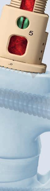
6 XRL. A modular expandable radiolucent vertebral body replacement system. Instrumentation One instrument provides: Holding and insertion Distraction/locking Repositioning of implant, if needed Ratchet and continuous expansion options for tactile feedback Precision control during implant insertion Scale indicates the amount of distraction achieved Handle repositioning prior to insertion for intraoperative visualization Approach Options Anterior (1) Anterolateral (2) Lateral (3) Posterolateral (4) DePuy Synthes XRL Surgical Technique
7 AO Spine Principles The four principles to be considered as the foundation for proper spine patient management underpin the design and delivery of the Curriculum: Stability Alignment Biology Function. Stability Stabilization to achieve a specific therapeutic outcome axial sagittal coronal Alignment Balancing the spine in three dimensions Biology Etiology, pathogenesis, neural protection, and tissue healing Function Preservations and restoration of function to prevent disability Copyright 2012 by AOSpine XRL Surgical Technique DePuy Synthes 5
8 Indications and Contraindications XRL serves as a replacement for injured vertebral bodies to stabilize the anterior thoracic and lumbar spine (Th3-L5). The approach can be anterior, anterolateral, lateral or posterolateral. Depending on the pathological situation, a defect height of 22 mm to 142 mm can be corrected, allowing XRL to be used for one and two level vertebral body defects. Indications Fractures with destruction of the anterior column in the thoracic and lumbar spine Post traumatic malalignment Replacement of vertebral bodies following tumor resection in the thoracic and lumbar spine Reconstruction of the anterior column following an infection Contraindications For sole anterior treatment of advanced osteoporosis. In this case an additional dorsal treatment should be carried out in addition to the anterior treatment Diffuse spinal tumors In the absence of intact neighboring segments Notes: As with all vertebral body replacement systems, XRL is not suitable as a stand-alone device, and must be used together with an internal fixation system (such as ArcoFix, MATRIX or USS Fracture) to absorb compression forces, tensile forces and torsional moments. Additional internal fixation system must not be removed before solid bony fusion occurs. 6 DePuy Synthes XRL Surgical Technique
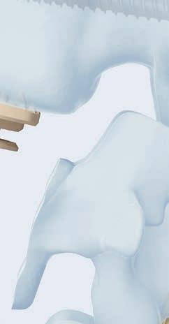
9 Preparation 1 Access Various approaches are suitable depending on the affected spinal level involved. The following surgical technique is described using a lateral approach from the left at L1. As with all vertebral body replacement systems, preoperative planning is always required to ascertain that the implant matches the patient specific anatomy. Note: The optimal approach respecting the patient specific situation has to be established by the surgeon. 2 Perform corpectomy Perform a partial or complete corpectomy as required. Remove the superficial layers of the entire cartilaginous endplates and expose bleeding bone. Note: Excessive removal of subchondral bone may weaken the vertebral endplate. If the entire endplate is removed, subsidence and a loss of segmental stability may occur. XRL Surgical Technique DePuy Synthes 7


10 Insert Trial Implant The XRL Vertebral Body Replacement contains a complete line of central body and endplate trial implants that correspond to each central body and endplate implant. Trials are placed into the corpectomy site intraoperatively to determine the appropriate endplate footprint, angle, and central body height. 1 Determine defect Instrument Metal Tape Gauge The metal tape gauge can be used to determine the overall defect. Note: If the corpectomy height is less than 34 mm, then proceed to step 4 of this section and use the integrated trials. 8 DePuy Synthes XRL Surgical Technique


11 2 Select endplate footprint size and angle Instruments XRL Medium Endplate Trials Instrument for Footprint mm round mm 24 mm mm 30 mm The endplate footprint trial can be adjusted to represent the desired approach. Pull the sleeve and turn the endplate trial to the desired position. Release the sleeve to lock the position of the trial. Determine the footprint using the endplate footprint trial. Determine the angle using lateral x-ray imaging. Note: Make sure that the endplates contact the maximum area of the neighboring vertebral bodies but do not project over the edge. XRL Surgical Technique DePuy Synthes 9
; therefore, 1 mm clearance on each end of the trial is required.")

 29 mm 5 6.5 10 8.5 15 10.")
12 Insert Trial Implant 3 Determine central body size 1 The optimal central body height is calculated using endplate trial height which is found on the back of the module lid for reference. The trials do not account for the implant spikes (1); therefore, 1 mm clearance on each end of the trial is required. Optimal Central Body Height (CBH) = Overall defect Cranial trial endplate height Caudal trial endplate height Clearance for spikes 1 mm Example for 46 mm defect with a 5 cranial endplate and 10 caudal endplate: CBH = 46 mm 6.5 mm 8.5 mm 2 mm CBH = 29 mm Insert the selected trial endplates onto the trial central body. Align the etch lines before pressing the components together. Ensure there is no gap between the endplate and central body trial. Note: The endplate height is independent of the footprint. Warning: The trials are not for implantation and must be removed before insertion of the XRL implant. 1 mm 6.5 mm Medium Endplate Trial Angle 0 5 Height (mm) 29 mm mm 1 mm See page 28 for endplate and central body cross reference list. 11 DePuy Synthes XRL Surgical Technique


13 4 Insert trial Instrument XRL Medium Implant Holder Using the implant holder, insert the trial into the corpectomy site. Be sure the appropriate endplate is oriented in the cranial/caudal position and the etch lines on the trial are facing anterior. The optimal position for the trial is centered on the vertebral bodies with clearance to account for the implant spikes. Trials must always be securely held while in the wound. Note: Integrated implants do not have tall spikes and therefore the integrated trials are the same height as the corresponding collapsed implant. Change trial central body and endplates as necessary to achieve the optimal height, angle, and footprint. Warning: Do not excessively impact on trial implants and or implant holder. Use light impaction only. XRL Surgical Technique DePuy Synthes 11


.")

14 Implantation 1 Assemble implant 1 Select implant based on corresponding trial (see pages for trial/ implant list). If an integrated assembly is selected, skip to step 4, Prepare implant. The Endplate Assembly Fixture is found in the Trial Endplate Module. When assembling the implant, orient the caudal endplate into the endplate assembly fixture spike side down, aligning the A (Anterior) on the endplate with the A on the endplate assembly fixture (1). Position the central body with the locking ring facing the direction of the desired approach (2). Attach the caudal endplate first by pressing the endplate onto the octagon until fully seated. Repeat with the cranial endplate. 2 Note: The etch lines on the ends of the central body, the graft window, and the locking ring may all be used to indicate the direction of approach. Figure 3 shows the orientation of the etch line with respect to the caudal endplate for each approach option. Shown: Lateral left approach 3 Posterior Lateral left Anterior 12 DePuy Synthes XRL Surgical Technique
.")
.")

15 The etch line on the anterior aspect of the endplate ensures that both endplates are in the same direction (lateral left shown in Figure 4). 4 Warning: When pressing on the endplates, ensure the endplate properly seats on the central body. This can be checked visually (5). If the endplate is not properly seated, there is a risk that it could detach from the central body. The XRL central body must never be implanted without cranial and caudal endplates properly secured with endplate screws (See step 3, Attach endplate screws). 5 2 Reposition endplates (optional) Instrument XRL Endplate Removal Tool If necessary, the endplates can be repositioned by manually removing them from the central body, except for the round endplates which are removed using the XRL endplate removal tool. Be sure to perform endplate removal over a sterile table. Warning: Endplates release from central body abruptly. Make sure to have a firm grip on both the central body and the endplate during removal. To remove round endplates, align the tip of the XRL endplate removal tool with the slot in the endplate. Apply a slight, constant pressure and rotate the tool to release the endplate. XRL Surgical Technique DePuy Synthes 13


16 Implantation 3 Attach endplate screws Instruments XRL Medium Endplate Screwdriver Tip XRL Medium Torque Limiting Handle Align the endplate screwdriver tip into the open end of the torque limiting handle (1). Press until an audible click is heard. Align the tri-lobal feature of the tip and the etchings on the endplate screw. Lightly press the screw onto the screwdriver tip. The screwdriver tip will retain the screw (2). Align the torque limiting handle with the central body to prevent cross threading. While gripping the large end of the torque limiting handle, rotate the torque limiting handle clockwise to advance the screw through the caudal endplate and into the central body. Tighten until an audible click in the torque limiting handle is heard. Repeat this step to fixate the cranial endplate (3). 2 torque limiting handle 3 Note: Please follow torque limiting handle calibration instructions to ensure proper functionality. 14 DePuy Synthes XRL Surgical Technique


17 4 Prepare implant Instruments XRL Medium Cancellous Bone Graft Packing Preparation Tamp Prior to implanting, use the graft packing preparation tamp to facilitate packing of bone graft into the XRL implant. Graft can be packed through the cannulation in the endplate and graft windows. Warning: DO NOT pack graft into the locking ring. DO NOT use excessive force while packing graft. DO NOT pack graft while implant is loaded onto the spreader. XRL Surgical Technique DePuy Synthes 15
 03.807.348 XRL Release")
. The spreader tops are designed to prevent over-distracting the implant.")
. Release the button to set T-driver in the open position (3).")
18 Implantation 5 Assemble spreader instrument 1 2 Instruments XRL Spreader XRL Medium Shaft XRL Medium Spreader Tops, with 3, 5, 8, 10, or 15 mm distraction XRL Medium Spreader Top, with 5 mm distraction (Integrated) XRL Release Tool Assemble the appropriate size spreader top to the XRL spreader according to the implant central body size selected (See page 28 cross reference list). The spreader tops are designed to prevent over-distracting the implant. While holding the spreader with the shaft in the horizontal position, set ratchet lever to the OFF position (1). Press T-driver release button and pull back on the T-driver (2). Release the button to set T-driver in the open position (3). T-driver should not be fully removed during this operation. 11 DePuy Synthes XRL Surgical Technique


.")
. Do not force the spreader top onto the implant.")
. Verify the implant is secured over the sterile field.")
19 Insert the selected spreader top into the spreader shaft and insert the T-driver by gently pushing and turning the T-driver into the spreader assembly. Check functionality of the spreader top by rotating the T-driver. If properly assembled, the spreader top should translate during T-driver rotation, and the T-driver will remain retained by the spreader assembly. 6 Secure implant to spreader 1 2 Instruments XRL Spreader XRL Medium Shaft XRL Medium Spreader Tops, with 3, 5, 8, 10, or 15 mm distraction XRL Release Tool XRL Medium Spreader Top, Integrated 3 4 To load the implant, fully collapse the spreader top and set the ratchet lever to the OFF position (1). With the opening of the locking ring facing the instrument, slide the spreader top into the slots below the cranial endplate (2). Do not force the spreader top onto the implant. Set the ratchet lever ON (3) and slightly turn the T-driver clockwise until the spreader shaft engages the notch on the implant for a secure hold (4). Verify the implant is secured over the sterile field. 5 6 Set the scale to zero (5). Completely insert the release tool through the XRL spreader and into the locking ring (6). XRL Surgical Technique DePuy Synthes 17
. Release retaining collar.")


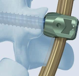
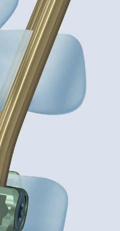
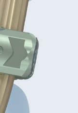
20 Implantation 7 Insert implant 2 Instrument XRL Spreader Prior to inserting the implant the spreader handle can be rotated at 90 increments to aid in visualization. Set ratchet lever to OFF position. With one hand gripping the spreader shaft, pull back on retaining collar and rotate the spreader handle to the desired position (, ). Release retaining collar. Verify that the spreader handle is locked into position. Reset scale to zero. Warning: Do not adjust spreader handle when ratchet lever is set to ON. This will result in premature distraction of the implant. Do not insert the implant into corpectomy until spreader handle is locked into desired position. Guide and position the implant with the spreader. Slight distraction of the vertebral bodies may be necessary to ease insertion. The optimal position for the implant is in the center of the vertebral body endplate. Maintain space around the endplate of the implant to allow peripheral bony fusion. Warning: Do not impact on spreader or implant. Do not manipulate implant unless both the slot and notch are engaged (see step 6, Secure Implant to Spreader). 11 DePuy Synthes XRL Surgical Technique


21 Verify the position of the implant using the image intensifier. Tantalum markers and a titanium locking ring is used to determine orientation of the implant The 1 mm diameter tantalum markers are embedded into the PEEK endplates to provide radiographic markers for intraoperative or postoperative imaging The anterior and medial/lateral markers are located approximately 1 mm from the edges of the implant. The posterior marker is located 1 mm from the edge of the round implant, and 2 mm from the edge of the anatomically shaped endplates. The cranial/caudal locations of the markers are 2 mm from the end of the pyramidal teeth. 1 mm 2 mm XRL Surgical Technique DePuy Synthes 11
, then turn the spreader T- driver clockwise (2) and expand the implant until the desired amount")
22 Implantation 8 Distract and check position 1 Instrument XRL Spreader Ensure the release tool is engaged and the ratchet lever is set to the ON position (1), then turn the spreader T- driver clockwise (2) and expand the implant until the desired amount of distraction is achieved. 2 Once the implant has been distracted, fully remove the release tool, (3) and with constant clockwise torque on the T- driver, place the ratchet lever in the OFF position (4). Note: The release tool may also be set in the resting position instead of being fully removed from the spreader. Pull up on the release tool until it travels ~15 mm and it will be retained by the spreader in the resting position DePuy Synthes XRL Surgical Technique
. When the slot is approximately 1 mm (2), the implant is locked and secured.")
.")

) is necessary to ensure full endplate surface contact (4).")
 is within 1 mm of the locking ring (b), the implant is fully expanded (5). Warning: Do not reuse XRL implants.")
23 Before removing the spreader, verify the locking ring is properly closed by collapsing the spreader top and visually inspecting the slot through the spreader top (1). When the slot is approximately 1 mm (2), the implant is locked and secured. If the slot is larger (3), re-expand the spreader top and distract the implant slightly to close the locking ring. If implant remains unlocked, follow step 9, Reposition implant (optional). If the locking ring is not visible, inspect lock after spreader is removed (see step 10). Remove the spreader from the implant by setting the ratchet lever to OFF and turning the T-driver counterclockwise. When spreader top is fully collapsed, the spreader can now be removed. Visually inspect implant/vertebral body interface for gaps to prevent point loading. If a gap is found, repositioning (see step 9, Reposition implant (optional)) is necessary to ensure full endplate surface contact (4) Verify the position of the implant using the image intensifier. The stop pin can be used to approximate the amount of distraction available. When stop pin (a) is within 1 mm of the locking ring (b), the implant is fully expanded (5). Warning: Do not reuse XRL implants. Do not reposition spreader handle during or after distraction. Do not impact on the XRL spreader or implant when repositioning the implant. Be sure to apply constant clockwise torque when switching the ratchet lever to OFF. Else, the T-driver may release abruptly. Distraction of the implant is only permitted with the XRL instrument set. 4 5 locking ring b stop pin a XRL Surgical Technique DePuy Synthes 22

.")
 and turn the T- driver clockwise until spreader engages the")


24 Implantation 9 Reposition implant (optional) 1 2 Instrument XRL Spreader To reposition the implant, fully collapse the spreader top and set the ratchet lever to the OFF position (1). 3 4 Be sure the release tool is removed or disengaged and set to the resting position (2). Slide the spreader top into the slots below the cranial endplate (3). Set ratchet lever to ON (4) and turn the T- driver clockwise until spreader engages the notch on the implant for a secure hold (5). Fully insert the release tool (6). With constant clockwise torque on the T-driver, set the ratchet lever to OFF position and compress the implant by turning the T-driver counterclockwise. Reposition the implant to the desired location and follow step 8 to re-distract implant. 5 6 Warning: Do not impact on the XRL spreader or implant when repositioning the implant. Be sure to apply constant clockwise torque when switching the ratchet lever to OFF. Else, the T-driver may release abruptly. Repositioning of the implant is only permitted with the XRL Instrument Set. 22 DePuy Synthes XRL Surgical Technique


, the implant is locked and secured.")


25 10 Verify lock 1 When the implant is in its final position, verify the locking ring on the central body is closed. When the slot is approximately 1 mm (1), the implant is locked and secured. If the slot is larger (2), re-engage the implant with the spreader, with the ratchet lever in the OFF position, and with the release tool fully removed, distract the implant slightly to close the locking ring. If implant remains unlocked, repeat step 9 and verify locking ring is closed. Warning: Locking ring must be properly closed to ensure final implant height is maintained. 2 XRL Surgical Technique DePuy Synthes 23

26 Supplemental Fixation 1 Apply bone material Instruments XRL Medium Cancellous Bone Graft Packing Tamp XRL Medium Cancellous Bone Graft Packing Preparation Tamp In situ graft packing must not occur until final implant position is achieved, as additional bone graft may obstruct repositioning of the implant. Before packing additional bone graft in or around the cage, use AP and lateral radiographs to verify the position of the implant in relation to the vertebral bodies using the tantalum markers and locking ring for references. The graft packing tamp has 2 different ends to fit the corresponding window of the expanded central body. The preparation tamp has an angled end that can be used to gain compression on graft that is not accessible with the graft packing tamp. Note: Graft packing tamp will not fit inside the window of integrated implant #1, however can still be used to tamp graft material. Warning: Do not use excessive force while packing graft. 22 DePuy Synthes XRL Surgical Technique

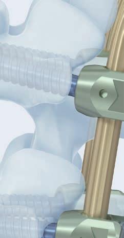
27 2 Apply internal fixation system For spinal stability and to maintain adequate compression on the construct, XRL must be used with an internal fixation system. Warning: Take care when applying supplemental fixation that the superior and inferior vertebral body endplates remain fixed. Manipulation of vertebral bodies may cause the XRL implant to shift in the wound possibly resulting in a need to reposition the implant. XRL Surgical Technique DePuy Synthes 22


 Various lordotic/kyphotic")

 to 36 mm (fully")

28 Implants Modular XRL Implants XRL Medium 21 mm central body diameter Endplate footprint options: 21 mm round 21 mm 24 mm 26 mm 30 mm Construct heights range from 32 mm (fully compressed) to 142 mm (fully expanded) Various lordotic/kyphotic angulation options Integrated XRL Implants XRL Medium 21 mm central body diameter 21 mm endplate footprint Heights range from 22 mm (fully compressed) to 36 mm (fully expanded) 0 parallel endplates Note: All XRL implants are supplied sterile 26 DePuy Synthes XRL Surgical Technique

.")
29 Trial Implants The XRL vertebral body replacement contains a complete line of central body and endplate trials that correspond to each central body and endplate implant. Trials are placed into the corpectomy site intraoperatively to determine the appropriate implant footprint, lordotic/kyphotic angle and central body height. Use the central body and endplate trials to determine the largest implant size (integrated or modular) that will fit the corpectomy site. Trials may be secured and lowered into corpectomy defect using the implant holder. Allow 1 mm clearance on each end for the tall spikes on the endplates (modular only). Medium Trials (green) Medium Trial Endplates (green) Integrated Modular Modular Part Number Description Part Number Trial Implants Central Bodies Size Corresponding (mm) Implants Integrated S height, Integrated height, S Integrated height, S height S height S height S height S height S height S height S height S Part Number Description Corresponding (mm) Implants Round, S Round, S Round, S Round, S , S , S , S , S , S , S , S , S , S , S , S , S height S height S height S height S XRL Surgical Technique DePuy Synthes 27
30 Cross Reference List XRL Medium Cranial Endplate Footprint 21 mm 21 mm 24 mm 26 mm 30 mm Endplate Angle Endplate Height (mm) 1 mm Cranial Central Body Central Body Central Body Distraction Spreader Number Height (mm) Range (mm) Top 1* 22* 3 1 2* 24* 5 2 3* 28* Caudal 1 mm * Integrated Assembly, no endplates needed Caudal Endplate Footprint 21 mm 21 mm 24 mm 26 mm 30 mm Endplate Angle Endplate Height (mm) 28 DePuy Synthes XRL Surgical Technique
31 Instruments XRL Spreader For implanting, distracting, and compressing (repositioning the implant) Ratchet Lever A ratchet lever on the instrument handle allows for the manipulations of the XRL implant. Note: Release tool must be engaged with locking ring for implant manipulation. T-driver Release Allows the T-driver to be disengaged/removed from the spreader Ratchet Mode ON allows expansion of the implant Continuous Mode OFF allows expansion or compression of the implant Shaft Release Allows the spreader shaft to be removed from the spreader Retaining Collar Allows 90 rotation of the spreader handle prior to implantation Scale Used to determine the achieved amount of expansion T-driver Allows expansion or compression of the implant Clockwise = expansion Counterclockwise = compression XRL Surgical Technique DePuy Synthes 29


32 Instruments Metal Tape Gauge XRL Medium Shaft XRL Release Tool Enables implant repositioning XRL Medium Spreader Tops Available in six distraction ranges, dependent on the central body implant with 3 mm distraction with 5 mm distraction with 8 mm distraction with 10 mm distraction with 15 mm distraction with 5 mm distraction (integrated) XRL Medium Endplate Screwdriver Tip 30 DePuy Synthes XRL Surgical Technique


33 XRL Endplate Removal Tool Allows removal of round endplates from the central body XRL Medium Torque Limiting Handle XRL Medium Endplate Trials Instrument for Footprint mm round mm 24 mm mm 30 mm XRL Medium Cancellous Bone Graft Packing Tamps Tamp Preparation Tamp XRL Medium Implant Holder For holding the implant trials XRL Surgical Technique DePuy Synthes 31


34 XRL Cases Graphic Cases Graphic Case for XRL Medium Instruments Graphic Case for XRL Medium Trial Implants Vario Case Vario Case for XRL 32 DePuy Synthes XRL Surgical Technique
35 XRL Medium Instrument Set Instruments Metal Tape Gauge XRL Spreader XRL Medium Shaft XRL Release Tool XRL Medium Spreader Top with 3 mm distraction with 5 mm distraction with 8 mm distraction with 10 mm distraction with 15 mm distraction XRL Medium Endplate Screwdriver Tip XRL Endplate Removal Tool XRL Medium Spreader Top with 5 mm distraction (Integrated) XRL Medium Torque Limiting Handle XRL Medium Endplate Trials Instrument for Footprint mm round mm 24 mm mm 30 mm XRL Medium Cancellous Bone Graft Packing Tamp XRL Medium Cancellous Bone Graft Packing Preparation Tamp XRL Medium Implant Holder XRL Surgical Technique DePuy Synthes 33
36 XRL Medium Trial Instrument Set Trials XRL Medium Trial, Integrated, 0 Height mm 25 mm mm 29 mm mm 36 mm XRL Medium Trial, Central Body Height mm 27 mm mm 33 mm mm 39 mm mm 43 mm mm 52 mm mm 59 mm mm 66 mm mm 77 mm Also Available XRL Medium Trial, Central Body Height mm 88 mm mm 99 mm mm 110 mm mm 121 mm XRL Medium Trial, Endplate, 21 mm round XRL Medium Trial Endplate, 21 mm 24 mm XRL Medium Trial Endplate, 26 mm 30 mm DePuy Synthes XRL Surgical Technique
37 XRL Medium Implants XRL Medium, Integrated, 0, sterile Height S 22 mm 25 mm S 24 mm 29 mm S 28 mm 36 mm XRL Medium Central Body, sterile Height S 22 mm 27 mm S 25 mm 33 mm S 29 mm 39 mm S 33 mm 43 mm S 37 mm 52 mm S 44 mm 59 mm S 51 mm 66 mm S 62 mm 77 mm Also Available XRL Medium Central Body, sterile Height S 73 mm 88 mm S 84 mm 99 mm S 95 mm 110 mm S 106 mm 121 mm XRL Medium Endplate, 21 mm round, sterile S S S S 15 XRL Medium Endplate, 21 mm 24 mm, sterile S S S S S S 15 XRL Medium Endplate, 26 mm 30 mm, sterile S S S S S S S XRL Medium Endplate Screws, sterile XRL Surgical Technique DePuy Synthes 33
38 33 DePuy Synthes XRL Surgical Technique
39
40 08/ Synthes GmbH Eimattstrasse 3 CH-4436 Oberdorf Ö öAAbä This publication is not intended for distribution in the USA. All surgical techniques are available as PDF files at Synthes GmbH All rights reserved Version AA
Replacement Device A modular expandable radiolucent vertebral body replacement system
 XRL Vertebral Body Replacement Device A modular expandable radiolucent vertebral body replacement system SURGICAL TECHNIQUE TABLE OF CONTENTS Introduction XRL System 2 AO Principles 5 Indications and Contraindications
The vertebral body replacement with ratchet mechanism. Synex. Surgical Technique
 The vertebral body replacement with ratchet mechanism Synex Surgical Technique Image intensifier control This description alone does not provide sufficient background for direct use of DePuy Synthes products.
SYNEX The vertebral body replacement with ratchet mechanism
 SYNEX The vertebral body replacement with ratchet mechanism Instruments and implants approved by the AO Foundation. This publication is not intended for distribution in the USA. SURGICAL TECHNIQUE Image
ECD EXPANDABLE CORPECTOMY DEVICE Continuously Expandable Vertebral Body Replacement for Tumour Cases
 ECD EXPANDABLE CORPECTOMY DEVICE Continuously Expandable Vertebral Body Replacement for Tumour Cases Instruments and implants approved by the AO Foundation. This publication is not intended for distribution
Surgical technique. synex. The vertebral body replacement with ratchet mechanism.
 Surgical technique synex. The vertebral body replacement with ratchet mechanism. Table of contents Indications and contraindications 2 Implants 3 Surgical technique 4 Cleaning of instruments 10 Optional
Synex System TECHNIQUE GUIDE. An expandable vertebral body replacement device
 Synex System TECHNIQUE GUIDE An expandable vertebral body replacement device Original Instruments and Implants of the Association for the Study of Internal Fixation AO ASIF Synex System Overview The Synex
TSLP Thoracolumbar Spine Locking Plate
 Anterior thoracolumbar spine locking plate TSLP Thoracolumbar Spine Locking Plate Surgical Technique Image intensifier control This description alone does not provide sufficient background for direct use
Technique Guide. ECD Expandable Corpectomy Device. Continuously Expandable Vertebral Body Replacement for Tumour Cases.
 Technique Guide ECD Expandable Corpectomy Device. Continuously Expandable Vertebral Body Replacement for Tumour Cases. Table of Contents Introduction Overview 2 AO ASIF Principles 4 Indications and Contraindications
TELEFIX SURGICAL TECHNIQUE. Implant system for the anterior stabilization of the thoracolumbar spine
 TELEFIX Implant system for the anterior stabilization of the thoracolumbar spine Instruments and implants approved by the AO Foundation. This publication is not intended for distribution in the USA. SURGICAL
Interbody fusion cage for the transforaminal approach. Travios. Surgical Technique
 Interbody fusion cage for the transforaminal approach Travios Surgical Technique Image intensifier control This description alone does not provide sufficient background for direct use of DePuy Synthes
The Versatile Polyaxial Solution for the Universal Spine Systems. USS II Polyaxial. Surgical Technique
 The Versatile Polyaxial Solution for the Universal Spine Systems USS II Polyaxial Surgical Technique Image intensifier control This description alone does not provide sufficient background for direct use
VECTRA-T SURGICAL TECHNIQUE. The Translational Anterior Cervical Palate System. This publication is not intended for distribution in the USA.
 VECTRA-T The Translational Anterior Cervical Palate System This publication is not intended for distribution in the USA. SURGICAL TECHNIQUE Image intensifier control This description alone does not provide
LCP Medial Distal Tibia Plate, without Tab. The Low Profile Anatomic Fixation System with Angular Stability and Optimal Screw Orientation.
 LCP Medial Distal Tibia Plate, without Tab. The Low Profile Anatomic Fixation System with Angular Stability and Optimal Screw Orientation. Technique Guide LCP Small Fragment System Table of Contents Introduction
SynCage-C short. Surgical Technique. This publication is not intended for distribution in the USA.
 SynCage-C short Surgical Technique This publication is not intended for distribution in the USA. Instruments and implants approved by the AO Foundation. Table of contents Implants 2 Indications/contra-indications
Thoracolumbar Spine Locking Plate (TSLP) System. A low-profile plating system for anterior stabilization of the thoracic and lumbar spine.
 System. A low-profile plating system for anterior stabilization of the thoracic and lumbar spine.") Thoracolumbar Spine Locking Plate (TSLP) System. A low-profile plating system for anterior stabilization of the thoracic and lumbar spine. Technique Guide Instruments and implants approved by the AO Foundation
Thoracolumbar Spine Locking Plate (TSLP) System. A low-profile plating system for anterior stabilization of the thoracic and lumbar spine. Technique Guide Instruments and implants approved by the AO Foundation
Technique Guide. ArcoFix. Anterior-only reduction plate.
 Technique Guide ArcoFix. Anterior-only reduction plate. Table of Contents Introduction ArcoFix 2 AO Principles 4 Indications and Contraindications 5 Surgical Technique Preoperative Planning 6 Insert ArcoFix
VLIFT System Overview. Vertebral Body Replacement System
 VLIFT System Overview Vertebral Body Replacement System VLIFT System System Description The VLIFT Vertebral Body Replacement System consists of a Distractible In Situ (DIS) implant, which enables the surgeon
CSLP-Cervical Spine Locking Plate
 For anterior, cervical fixation CSLP-Cervical Spine Locking Plate Surgical Technique Image intensifier control This description alone does not provide sufficient background for direct use of DePuy Synthes
SYNCAGE EVOLUTION. This publication is not intended for distribution in the USA. SURGICAL TECHNIQUE
 SYNCAGE EVOLUTION This publication is not intended for distribution in the USA. SURGICAL TECHNIQUE Image intensifier control Warning This description alone does not provide sufficient background for direct
OBSOLETED. LCP Medial Distal Tibia Plate, without Tab. The Low Profile Anatomic Fixation System with Angular Stability and Optimal Screw Orientation.
 LCP Medial Distal Tibia Plate, without Tab. The Low Profile Anatomic Fixation System with Angular Stability and Optimal Screw Orientation. Surgical Technique LCP Small Fragment System This publication
C-THRU Anterior Spinal System
 C-THRU Anterior Spinal System Surgical Technique Manufactured From Contents Introduction... Page 1 Design Features... Page 2 Instruments... Page 3 Surgical Technique... Page 4 Product Information... Page
ARCH Laminoplasty System
 Dedicated System for Open-door Laminoplasty ARCH Laminoplasty System Surgical Technique Image intensifier control This description alone does not provide sufficient background for direct use of DePuy Synthes
LCP Low Bend Medial Distal Tibia Plates 3.5 mm. Anatomic plates with low profile head for intra- and extraarticular fractures.
 LCP Low Bend Medial Distal Tibia Plates 3.5 mm. Anatomic plates with low profile head for intra- and extraarticular fractures. Surgical Technique This publication is not intended for distribution in the
Solitaire Anterior Spinal System
 Surgical Technique Solitaire Anterior Spinal System Independent Stabilization for the Anterior Column Available in Titanium and Contents Introduction... Page 1 Design Features... Page 2 Instruments...
GIZA Surgical Technique
 GIZA Surgical Technique Vertebral Body Replacement System Manufactured by Titanium alloy material provides mechanical integrity during insertion and distraction, x-ray visibility, and biocompatibility*
ACIS Anterior Cervical Interbody Spacer
 Implants and Instruments for Interbody Fusion Available in both PEEK and ProTi 360º Titanium Integrated Technology ACIS Anterior Cervical Interbody Spacer Surgical Technique Image intensifier control This
USS II ILIO-SACRAL Modular System for Stable Fixation in the Sacrum and Illium
 USS II ILIO-SACRAL Modular System for Stable Fixation in the Sacrum and Illium Instruments and implants approved by the AO Foundation. This publication is not intended for distribution in the USA. TECHNIQUE
Augmentable Pedicle Screws for Osteoporotic Bone. Perforated Click X. Surgical Technique
 Augmentable Pedicle Screws for Osteoporotic Bone Perforated Click X Surgical Technique Image intensifier control This description alone does not provide sufficient background for direct use of DePuy Synthes
Collinear Reduction Clamp
 For minimally invasive fracture reduction Collinear Reduction Clamp Surgical Technique Image intensifier control This description alone does not provide sufficient background for direct use of DePuy Synthes
SYNFIX EVOLUTION SECURED SPACER SYSTEM
 SYNFIX EVOLUTION SECURED SPACER SYSTEM Instruments and implants for stand-alone anterior lumbar interbody fusion Instruments and implants approved by the AO Foundation. This publication is not intended
Cervical Solutions. Optio-C Anterior Cervical Plate. with Allograft/Autograft. Surgical Technique Guide
 Cervical Solutions Optio-C Anterior Cervical Plate with Allograft/Autograft Surgical Technique Guide 2 Optio-C Anterior Cervical Plate with Allograft/Autograft Surgical Technique Guide The Optio-C System
M.I.S. MAKE IT SMART IN ONE SYSTEM. Surgical Technique. Hip Knee Spine Navigation
 M.I.S. MAKE IT SMART IN ONE SYSTEM Surgical Technique Hip Knee Spine Navigation M.U.S.T. Mini Open Surgical Technique Hip Knee Spine Navigation 2 C O N T E N T S 1 INTRODUCTION 4 2 SURGICAL TECHNIQUE 5
PERFORATED CLICK X Augmentable pedicle screws for osteoporotic bone
 PERFORATED CLICK X Augmentable pedicle screws for osteoporotic bone Instruments and implants approved by the AO Foundation. This publication is not intended for distribution in the USA. SURGICAL TECHNIQUE
The Implant. (Klappen außen sind nur 192 mm breit!) Ordering information. You start we help with our clearly arranged Starter Kit:
 Ordering information. You start we help with our clearly arranged Starter Kit:") ATHLET PRODUCT INFORMATION The Implant 1 construct = 1 main body + 1 end body (Klappen außen sind nur 192 mm breit!) Latch mechanism for secure connection of the implant components Ordering information
ATHLET PRODUCT INFORMATION The Implant 1 construct = 1 main body + 1 end body (Klappen außen sind nur 192 mm breit!) Latch mechanism for secure connection of the implant components Ordering information
Thoracolumbar Anterior Compression (TAC) System. Allows distraction, compression, and lateral fixation of the lower thoracic and lumbar spine.
 System. Allows distraction, compression, and lateral fixation of the lower thoracic and lumbar spine.") Thoracolumbar Anterior Compression (TAC) System. Allows distraction, compression, and lateral fixation of the lower thoracic and lumbar spine. Technique Guide Instruments and implants approved by the AO
Thoracolumbar Anterior Compression (TAC) System. Allows distraction, compression, and lateral fixation of the lower thoracic and lumbar spine. Technique Guide Instruments and implants approved by the AO
SynCage. Surgical Technique. This publication is not intended for distribution in the USA. Instruments and implants approved by the AO Foundation.
 SynCage Surgical Technique This publication is not intended for distribution in the USA. Instruments and implants approved by the AO Foundation. Image intensifier control Warning This description alone
Conventus CAGE PH Surgical Techniques
 Conventus CAGE PH Surgical Techniques Conventus Orthopaedics The Conventus CAGE PH (PH Cage) is a permanent implant comprised of an expandable scaffold, made from nitinol and titanium, which is deployed
HawkeyeTM Peek. surgical technique
 HawkeyeTM Peek surgical technique Introduction The ChoiceSpine HAWKEYE Vertebral Body Replacement (VBR) System is intended for use in the thoracolumbar spine (T1 - L5) to replace a collapsed, damaged,
LUMBAR POSTERIOR MINIMALLY INVASIVE SYSTEM. Surgical Technique
 LUMBAR POSTERIOR MINIMALLY INVASIVE SYSTEM Surgical Technique Joint Spine Sports Med M.U.S.T. Mini Open Surgical Technique Joint Spine Sports Med CAUTION Federal law (USA) restricts this device to sale
Luminary ALIF. Disc preparation and implant insertion instruments.
 Luminary ALIF. Disc preparation and implant insertion instruments. Technique Guide Instruments and implants approved by the AO Foundation Table of Contents Introduction Luminary ALIF 2 AO Principles 4
In-Space. Percutaneous interspinous distraction.
 In-Space. Percutaneous interspinous distraction. Surgical Technique PRODUCT OBSOLETED 30th September 207 DSEM/SPN/095/0344() This publication is not intended for distribution in the USA. Instruments and
In-Space. Interspinous distraction through a mini-open, posterior, unilateral approach.
 In-Space. Interspinous distraction through a mini-open, posterior, unilateral approach. Surgical Technique Posterior Approach PRODUCT OBSOLETED 30th September 2017 DSEM/SPN/0915/0348(1) This publication
Technique Guide. Compact 2.0 LOCK Mandible. The locking system for the mandible.
 Technique Guide Compact 2.0 LOCK Mandible. The locking system for the mandible. Table of Contents Introduction Compact 2.0 LOCK Mandible 2 AO Principles 4 Indications and Contraindications 5 Surgical
Valencia Pedicle Screw Surgical Technique
 Valencia Pedicle Screw Surgical Technique VALENCIA CIRCUIT TABLE OF CONTENTS Design Rationale Indications for Use Surgical Technique 1. Pedicle Preparation 2. Screw Insertion 3. Rod Placement 4. Locking
Surgical technique. SynCage-C short
 Surgical technique SynCage-C short Table of contents Implants 2 Indications/contra-indications 3 Surgical technique 4 Image intensifier control Warning This description is not sufficient for immediate
nva Anterior Lumbar Interbody Fusion System
 nva Anterior Lumbar Interbody Fusion System 1 IMPORTANT INFORMATION FOR PHYSICIANS, SURGEONS, AND/OR STAFF The nv a, nv p, and nv t are an intervertebral body fusion device used in the lumbar spine following
Imola Lateral IBF System Surgical Technique
 Imola Lateral IBF System Surgical Technique IMOLA CIRCUIT TABLE OF CONTENTS Design Rationale Instructions for Use Surgical Technique 1. Table Mounting 2. Surgical Planning & Targeting 3. Access and Preparation
Cannulated Angled Blade Plate 3.5 and 4.5, 90.
 Cannulated Angled Blade Plate 3.5 and 4.5, 90. Technique Guide This publication is not intended for distribution in the USA. Instruments and implants approved by the AO Foundation. Table of Contents Introduction
Technique Guide. T-PAL. Transforaminal posterior atraumatic lumbar spacer system.
 Technique Guide T-PAL. Transforaminal posterior atraumatic lumbar spacer system. Table of Contents Introduction T-PAL 2 AO Principles 4 Indications and Contraindications 5 Surgical Technique Preparation
PEEK Cage for Posterior Lumbar Interbody Fusion (PLIF) Plivios Revolution. Surgical Technique
 Plivios Revolution. Surgical Technique") PEEK Cage for Posterior Lumbar Interbody Fusion (PLIF) Plivios Revolution Surgical Technique Image intensifier control This description alone does not provide sufficient background for direct use of DePuy
PEEK Cage for Posterior Lumbar Interbody Fusion (PLIF) Plivios Revolution Surgical Technique Image intensifier control This description alone does not provide sufficient background for direct use of DePuy
nvt Transforaminal Lumbar Interbody Fusion System
 nvt Transforaminal Lumbar Interbody Fusion System 1 IMPORTANT INFORMATION FOR PHYSICIANS, SURGEONS, AND/OR STAFF The nv a, nv p, and nv t are an intervertebral body fusion device used in the lumbar spine
SAMSON. Expandable Vertebral Body Replacement
 SAMSON Expandable Vertebral Body Replacement System SAMSON is an expandable vertebral body replacement system which is used for the anterior stabilisation of the spinal column, from the upper thoracic
nvp Posterior Lumbar Interbody Fusion System
 nvp Posterior Lumbar Interbody Fusion System 1 IMPORTANT INFORMATION FOR PHYSICIANS, SURGEONS, AND/OR STAFF The nv a, nv p, and nv t are an intervertebral body fusion device used in the lumbar spine following
Apache Cervical Interbody Fusion Device. Surgical Technique. Page of 13. LC-005 Rev F
 LC-005 Rev F Apache Cervical Interbody Fusion Device Page of 13 Surgical Technique INDICATIONS: When used as an intervertebral body fusion device, the Genesys Spine Interbody Fusion System is indicated
ACIS Anterior Cervical Interbody Spacer
 An enhanced system of implants and instruments for interbody fusion ACIS Anterior Cervical Interbody Spacer Surgical Technique Image intensifier control This description alone does not provide sufficient
SYNFIX. LR Stand Alone Spacer. Instruments and implants for stand alone anterior lumbar interbody fusion (ALIF). Technique Guide
. Technique Guide") SYNFIX LR Stand Alone Spacer. Instruments and implants for stand alone anterior lumbar interbody fusion (ALIF). Technique Guide Table of Contents Introduction SYNFIX LR Stand Alone Spacer 2 AO Principles
SYNFIX LR Stand Alone Spacer. Instruments and implants for stand alone anterior lumbar interbody fusion (ALIF). Technique Guide Table of Contents Introduction SYNFIX LR Stand Alone Spacer 2 AO Principles
USS Variable Axis Screw
 USS Variable Axis Screw Polyaxial side-opening pedicle screw Surgical technique Original Instruments and Implants of the Association for the Study of Internal Fixation AO/ASIF USS Variable Axis Screw
Technique Guide. Insight Retractor. Minimal invasive access system to the posterior thoracolumbar spine.
 Technique Guide Insight Retractor. Minimal invasive access system to the posterior thoracolumbar spine. Table of Contents Introduction Insight Retractor 2 AO Principles 4 Indications and Contraindications
LCP Medial Proximal Tibial Plate 3.5. Part of the Synthes small fragment Locking Compression Plate (LCP) system.
 system.") LCP Medial Proximal Tibial Plate 3.5. Part of the Synthes small fragment Locking Compression Plate (LCP) system. Technique Guide This publication is not intended for distribution in the USA. Instruments
LCP Medial Proximal Tibial Plate 3.5. Part of the Synthes small fragment Locking Compression Plate (LCP) system. Technique Guide This publication is not intended for distribution in the USA. Instruments
Technique Guide. 3.5 mm LCP Low Bend Medial Distal Tibia Plates. Part of the Synthes locking compression plate (LCP) system.
 system.") Technique Guide 3.5 mm LCP Low Bend Medial Distal Tibia Plates. Part of the Synthes locking compression plate (LCP) system. Table of Contents Introduction 3.5 mm LCP Low Bend Medial Distal Tibia Plates
Technique Guide 3.5 mm LCP Low Bend Medial Distal Tibia Plates. Part of the Synthes locking compression plate (LCP) system. Table of Contents Introduction 3.5 mm LCP Low Bend Medial Distal Tibia Plates
Advantage ALIF. Keith Shevlin Managing Director
 Advantage ALIF Unit 10, 9-11 Myrtle Street, Crows Nest NSW 2065 Keith Shevlin Managing Director keithshevlin@precisionsurgical.com.au Advantage ALIF Introduction & Indications for Use 1 Surgical Technique
TABLE OF CONTENTS. ShurFit Anterior Cervical Interbody Fusion (ACIF) System Overview 2. Implant Specifications 3. Instrument Features 4
 System Overview 2. Implant Specifications 3. Instrument Features 4") Surgical Technique TABLE OF CONTENTS ShurFit Anterior Cervical Interbody Fusion (ACIF) System Overview 2 Product Highlights 2 Indications 2 Implant Specifications 3 Instrument Features 4 Surgical Technique
Surgical Technique TABLE OF CONTENTS ShurFit Anterior Cervical Interbody Fusion (ACIF) System Overview 2 Product Highlights 2 Indications 2 Implant Specifications 3 Instrument Features 4 Surgical Technique
PROXIMAL FEMORAL NAIL REMOVAL SET
 PROXIMAL FEMORAL NAIL REMOVAL SET for PFN, TFN and PFNA/PFNA-II Instruments and Implants approved by the AO Foundation. This publication is not intended for distribution in the USA. SURGICAL TECHNIQUE
MATRIX Spine System Deformity
 A Solution for Simple and Complex Spine Pathology MATRIX Spine System Deformity Surgical Technique Image intensifier control This description alone does not provide sufficient background for direct use
Contact Fusion Cage. Surgical Technique
 Contact Fusion Cage Surgical Technique Image intensifier control This description alone does not provide sufficient background for direct use of DePuy Synthes products. Instruction by a surgeon experienced
FACET WEDGE. Facet joint fixation device.
 FACET WEDGE. Facet joint fixation device. Technique Guide Synthes FACET WEDGE Technique Guide /44 Synthes FACET WEDGE Technique Guide /44 Table of Contents Introduction FACET WEDGE 3 AO Principles 4 Indications
PILLAR AL. Anterior Lumbar Interbody Fusion (ALIF) and Partial Vertebral Body Replacement (pvbr) PEEK Spacer System OPERATIVE TECHNIQUE
 and Partial Vertebral Body Replacement (pvbr) PEEK Spacer System OPERATIVE TECHNIQUE") PILLAR AL PEEK Spacer System Anterior Lumbar Interbody Fusion (ALIF) and Partial Vertebral Body Replacement (pvbr) OPERATIVE TECHNIQUE Table of Contents 1 INTRODUCTION 2 PRE-OPERATIVE TECHNIQUE 3 OPERATIVE
PILLAR AL PEEK Spacer System Anterior Lumbar Interbody Fusion (ALIF) and Partial Vertebral Body Replacement (pvbr) OPERATIVE TECHNIQUE Table of Contents 1 INTRODUCTION 2 PRE-OPERATIVE TECHNIQUE 3 OPERATIVE
T-PAL. Transforaminal Posterior Atraumatic Lumbar Cage System.
 T-PAL. Transforaminal Posterior Atraumatic Lumbar Cage System. Technique Guide This publication is not intended for distribution in the USA. Instruments and implants approved by the AO Foundation. Image
USS Variable Axis Screw (VAS) System. For posterior fixation of the lumbar spine.
 System. For posterior fixation of the lumbar spine.") USS Variable Axis Screw (VAS) System. For posterior fixation of the lumbar spine. Technique Guide Instruments and implants approved by the AO Foundation Table of Contents Introduction USS Variable Axis
USS Variable Axis Screw (VAS) System. For posterior fixation of the lumbar spine. Technique Guide Instruments and implants approved by the AO Foundation Table of Contents Introduction USS Variable Axis
Surgical Technique. CONQUEST FN Femoral Neck Fracture System
 Surgical Technique CONQUEST FN Femoral Neck Fracture System Table of Contents Introduction... 3 Indications... 3 Product Overview... 4 Surgical Technique... 5 Patient Positioning... 5 Reduce the Fracture...
ARCH Laminoplasty System. Dedicated System for Open-door Laminoplasty.
 ARCH Laminoplasty System. Dedicated System for Open-door Laminoplasty. Surgical Technique This publication is not intended for distribution in the USA. Instruments and implants approved by the AO Foundation.
Mandible External Fixator II. Provides treatment for fractures of the maxillofacial area.
 Mandible External Fixator II. Provides treatment for fractures of the maxillofacial area. Technique Guide This publication is not intended for distribution in the USA. Instruments and implants approved
Royal Oak IBFD System Surgical Technique Posterior Lumbar Interbody Fusion (PLIF)
") Royal Oak IBFD System Surgical Technique Posterior Lumbar Interbody Fusion (PLIF) Preoperative Planning Preoperative planning is necessary for the correct selection of lumbar interbody fusion devices.
Royal Oak IBFD System Surgical Technique Posterior Lumbar Interbody Fusion (PLIF) Preoperative Planning Preoperative planning is necessary for the correct selection of lumbar interbody fusion devices.
100 Interpace Parkway Parsippany, NJ
 100 Interpace Parkway Parsippany, NJ 07054 www.biometspine.com 800-526-2579 All trademarks are the property of Biomet, Inc. or one of its subsidiaries, unless otherwise indicated. Rx Only. 2009 EBI, LLC.
MODULAR DESIGN OFFERS FREEDOM OF CHOICE. Surgical Technique
 MODULAR DESIGN OFFERS FREEDOM OF CHOICE Surgical Technique Joint Spine Sports Med MectaLIF Anterior Surgical Technique 2 INDEX 1. INTRODUCTION 4 1.1 Material & Marker 5 2. INDICATIONS 5 3. CONTRAINDICATIONS
Technique Guide. Zero-P VA. Variable angle zero-profile anterior cervical interbody fusion (ACIF) device.
 device.") Technique Guide Zero-P VA. Variable angle zero-profile anterior cervical interbody fusion (ACIF) device. Image intensifier control Warning This description alone does not provide sufficient background
Technique Guide Zero-P VA. Variable angle zero-profile anterior cervical interbody fusion (ACIF) device. Image intensifier control Warning This description alone does not provide sufficient background
Threshold Pedicular Fixation System Surgical Technique
 Threshold Pedicular Fixation System Surgical Technique Table of Contents Patient Preparation and Positioning... 2 Determining Incision Location... 3 Assembling the Cannulated Awl... 4 Guide Wire Placement...
product overview Implant heights range from 8mm-20mm in 2mm increments, with two lordocic angle options of 6 and 12.
 ETHOS A-Spacer PEEK System Surgical Technique Guide Synchronizing Medical Innovation with Global Markets product overview The SyncMedical Ethos PEEK IBF System is an intervertebral body fusion device for
Zero-P Instruments and Implants. Zero-profile anterior cervical interbody fusion (ACIF) device.
 device.") Zero-P Instruments and Implants. Zero-profile anterior cervical interbody fusion (ACIF) device. Technique Guide Instruments and implants approved by the AO Foundation Table of Contents Introduction Zero-P
Zero-P Instruments and Implants. Zero-profile anterior cervical interbody fusion (ACIF) device. Technique Guide Instruments and implants approved by the AO Foundation Table of Contents Introduction Zero-P
Surgical Technique INTERSOMATIC CERVICAL CAGE
 R INTERSOMATIC CERVICAL CAGE NEOCIF IMPLANTS NEOCIF is an implant designed to make anterior cervical interbody fusion (ACIF) easier and to remove the need for structural autologous graft. The cage is made
BAK/C Cervical Anterior Interbody Fusion System
 Surgical Technique BAK/C Cervical Anterior Interbody Fusion System The Comfortable Choice for Cervical Fusion BAK/C Cervical Surgical Technique 1 The BAK/C Cervical Fusion System is an alternative to conventional
TABLE OF CONTENTS. 2 (8144 Rev 2)
") 1 (8144 Rev 2) TABLE OF CONTENTS Introduction Conventus CAGE TM - Proximal Humerus...3 Indications and Contraindications...4 Surgical Summary...5 Patient Positioning & Approach...6 Surgical Technique Plate
1 (8144 Rev 2) TABLE OF CONTENTS Introduction Conventus CAGE TM - Proximal Humerus...3 Indications and Contraindications...4 Surgical Summary...5 Patient Positioning & Approach...6 Surgical Technique Plate
Alamo C. Cervical Interbody System Surgical Technique. An Alliance Partners Company
 Cervical Interbody System Surgical Technique Table of Contents Indications for Use................................1 Device Description............................... 1 Alamo C Instruments..............................
Surgical Technique. Apache Anterior Lumbar Interbody Fusion
 Surgical Technique Apache Anterior Lumbar Interbody Fusion 2 Table of Contents Page Preoperative Planning 4 Patient Positioning 4 Disc and Endplate Preparation 4 Distraction/Size Selection 5 Implantation
VA-LCP Anterior Clavicle Plate. The anatomically precontoured fixation system with angular stability for clavicle shaft and lateral clavicle.
 Technique Guide VA-LCP Anterior Clavicle Plate. The anatomically precontoured fixation system with angular stability for clavicle shaft and lateral clavicle. Table of Contents Introduction VA-LCP Anterior
Alignment Rod. For intraoperatively confirming correction of the mechanical leg axis.
 Alignment Rod. For intraoperatively confirming correction of the mechanical leg axis. Easy to use Accuracy of surgery Reduces X-ray exposure Table of Contents Introduction Alignment Rod 2 Handling Technique
Low Bend Distal Tibia Plates
 Part of the DePuy Synthes Locking Compression Plate (LCP ) System 3.5 mm LCP Low Bend Medial Distal Tibia Plates Surgical Technique Table of Contents Introduction 3.5 mm LCP Low Bend Medial Distal Tibia
Veyron -C Anterior Cervical System Surgical Technique
 Veyron -C Anterior Cervical System Surgical Technique 2 Veyron-C Anterior Cervical System Surgical Technique Veyron-C Anterior Cervical System Surgical Technique Description, Indications & Contraindications...3
Alamo T Transforaminal Lumbar Interbody System Surgical Technique
 Transforaminal Lumbar Interbody System Surgical Technique Table of Contents Indications and Device Description.............. 1 Alamo T Implant Features and Instruments...........2 Surgical Technique......................
Trephine System. Principle-based anterior lumbar interbody fusion.
 Trephine System. Principle-based anterior lumbar interbody fusion. Technique Guide Instruments and implants approved by the AO Foundation Table of Contents Introduction Trephine System 2 AO Principles
MatrixNEURO. The next generation cranial plating system.
 MatrixNEURO. The next generation cranial plating system. Technique Guide CMF Matrix This publication is not intended for distribution in the USA. Instruments and implants approved by the AO Foundation
Technique Guide. VA-Locking Intercarpal Fusion System. Variable angle locking technology for mediocarpal partial arthrodesis.
 Technique Guide VA-Locking Intercarpal Fusion System. Variable angle locking technology for mediocarpal partial arthrodesis. Table of Contents Introduction VA-Locking Intercarpal Fusion System 2 Indications
TECHNICAL BROCHURE. Capture Facet Fixation System
 TECHNICAL BROCHURE Capture Facet Fixation System Table of Contents Product Overview...2 Instruments...4 Capture Facet Screw Surgical Technique Patient Preparation and Positioning...6 Guide Pin Placement...7
Surgical Technique Guide
 Sacroiliac Joint Fusion System Surgical Technique Guide Moving Life Forward Table of Contents SiCure Implant Overview...2 SiCure System Information...3 X-ray Basics...4 Patient Positioning....5 Surgical
Cervical Solutions. Optio-C Anterior Cervical PEEK. Interbody System. Surgical Technique Guide
 Cervical Solutions Optio-C Anterior Cervical PEEK Interbody System Surgical Technique Guide 2 Optio-C Anterior Cervical PEEK Interbody System Surgical Technique Guide The Optio-C System provides a zero-profile
SURGICAL TECHNIQUE MANUAL. InterFuse T
 1 CONTENTS InterFuse T Product Description 3 Indications for Use 3 X-Ray Marker Locations 4 Product Specifications 4 Instrument Set 5 Step 1 Preoperative Planning 8 Patient Positioning 8 Step 2 Disc Removal
LCP Superior Clavicle Plate. The anatomically precontoured fixation system with angular stability for clavicle shaft and lateral clavicle.
 LCP Superior Clavicle Plate. The anatomically precontoured fixation system with angular stability for clavicle shaft and lateral clavicle. Surgical Technique This publication is not intended for distribution
EXACTECH SPINE. Operative Technique. Cervical Spacer System. Surgeon focused. Patient driven. TM
 EXACTECH SPINE Operative Technique Cervical Spacer System Surgeon focused. Patient driven. TM ACAPELLA ONE Acapella One Cervical Spacer System is an anterior cervical discectomy and fusion device with