, , , ,
|
|
|
- Derrick Walton
- 6 years ago
- Views:
Transcription


1 Pivot Guardian Hip Distraction System User Guide , , , ,
2
3 Table of Contents 1 Warnings and Cautions Warnings Cautions Product Description Understanding the Device Hip Distractor Frame Accessories Surgical Table Compatibility Chart Intended Use Contraindications Cleaning and Disinfection Cleaning Disinfection Device Set-up Transport the Device to the Surgical Area Remove the Storage Bin Attach the Hip Distractor Frame to the Surgical Table Adjust the Hip Distractor Frame for Surgeon Height Attach the Tabletop Extension Prepare the Fine-Traction Element Patient Set-up Secure the Patient-Positioning Pad Put the Boot Liners on the Patient Put the Boots on the Patient Position the Patient Put the Hip Distractor in Glide Mode Connect the Patient s Boots to the Device Put the Patient into the Trendelenburg Position (Optional) Install the Perineal Post and Pad Adjust the Hip Distractor for Patient Height Drape the Device Intra-procedure Use of the Hip Distractor Pull Gross Traction Increase or Decrease Fine Traction
4 8.3 Decrease Gross Traction Abduct and Adduct Rotate the Foot Internally or Externally Flex the Hip Post-Op Procedures Remove the Boots and Boot Liners Dispose of Single-Use Devices Prepare the Device for Storage Remove the Base from the Surgical Table Attach the Storage Bin to the Hip Distractor Frame Remove the Tabletop Extension from the Surgical Table Store the Device Technical Specifications Symbol Definitions
5 1 Warnings and Cautions Please read this manual and follow its instructions carefully. The words warning, caution, and note carry special meanings and should be carefully reviewed: Warning: Indicates measures to avoid potential serious injury to the user and the patient and/or damage to this device. Caution: Indicates risks to the equipment. Failure to follow cautions may result in product damage. Note: Provides special information to clarify instructions or present additional useful information. The warranty is void if any of these warnings or cautions are disregarded. 1.1 Warnings 1. Carefully unpack the unit and check for any damage that may have occurred during shipment. If damage is detected, contact your Stryker representative. 2. Read this operating manual thoroughly and be familiar with its contents prior to setting up or using this equipment. The information provided in these instructions are the manufacturer s suggested techniques. The final disposition of each patient s care as related to the use of this device rests with the attending surgeon. 3. Do not use the device for patients weighing more than 400 lbs (181.4 kg) as such use may result in damage to the device and possible injury to the patient, and/or healthcare professionals. 4. Use only the accessories and surgical tables recommended in these instructions. Use of unauthorized accessories or surgical tables may result in harm to the patient and may damage the device. 5. If you want to secure the device when the device is not attached to a surgical table, retract the base wheels before applying the abduction locks. If the abduction locks are applied when the base wheels are deployed, there is a tipping danger that could cause injury or damage the device. 6. Use Perioperative Standards and Recommended Practices. Monitor patient contact points throughout the procedure. Proper perioperative and intra-operative procedures must be followed to prevent pressure sore development, neuropathy, hypertension, hypothermia, and venous stasis and pooling, especially when using the perineal post. 7. When applying safety straps around the patient, monitor the patient to avoid pressure points that could cause nervous system or circulatory impairments. 8. Limit the time that the patient is in traction, as excessive traction duration may result in harm to the patient. 9. Ensure patient s bare back completely contacts the patient safety pad to reduce patient sliding when traction is pulled. 3
6 1.2 Cautions 1. Caution: Federal law (United States of America) restricts this device to use by, or on order of, a physician. 2. Before each use, inspect the device and all of its accessories for damage. Test to make sure all parts are functioning properly. Do not use if the device is damaged or if any of its parts are not working properly. Do not use any accessory that is damaged. 3. Do not modify this equipment without authorization from the manufacturer. Do not attempt internal repairs or adjustments not specifically detailed in this manual. Refer any adjustments, modifications, and/or repairs to Stryker Endoscopy or its authorized representatives. 4. Pay close attention to the care and cleaning instructions in this manual. Failure to follow these instructions may result in product damage. 5. Exercise caution when transporting this device. Impact with another object may cause damage to the device. If an impact occurs, visually inspect the device for damage and make sure it is in working order. If the device is damaged or not working properly, do not use it. 6. Handle the boots carefully. Boots may break if dropped. 4
7 2 Product Description The Stryker Pivot Guardian Hip Distraction System allows surgeons to perform hip procedures in Trendelenburg position, eliminating the need for a perineal post. The system consists of the hip distractor frame, a tabletop extension with pad, boots, boot liners, a patient-positioning kit, and a clear, sterile drape. An optional perineal post and pad may also be used. The Stryker Pivot Guardian Hip Distraction System is to be used in an operating room or other treatment room. The device is mobile and may be moved from one room to another. The device may be used several times throughout the day. It may only be used with compatible surgical tables (See section 2.2). Note: The device should be cleaned and inspected prior to each use. The Stryker Pivot Guardian Hip Distraction System must be used only by a person with a medical license and by experienced medical professionals who have familiarized themselves with the system and these instructions. 2.1 Understanding the Device These instructions cover the Stryker Pivot Guardian Hip Distraction System, which includes the hip distractor frame (part number ) and its accessories. 5
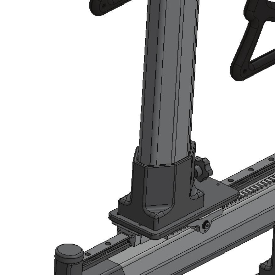
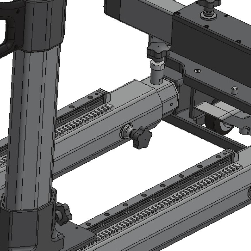
8 2.1.1 Hip Distractor Frame Hip Distractor Frame 1 Fine-traction element Increases and decreases fine traction. 2 Vertical spar (with gross traction trigger handle and handle bar) Increases and decreases gross traction; allows hip to be flexed 3 Horizontal spar Supports the vertical spar when gross traction is increased or decreased. 4 Base with base arms Secures the hip distractor frame to compatible surgical tables. Note: The base arms should be inverted for shipping and storage. They will need to be oriented properly prior to use, as shown in the image above. The fine-traction element, gross traction trigger handle, and base with base arms each have individual parts that will be referenced in these instructions. The most common ones are outlined here: 6
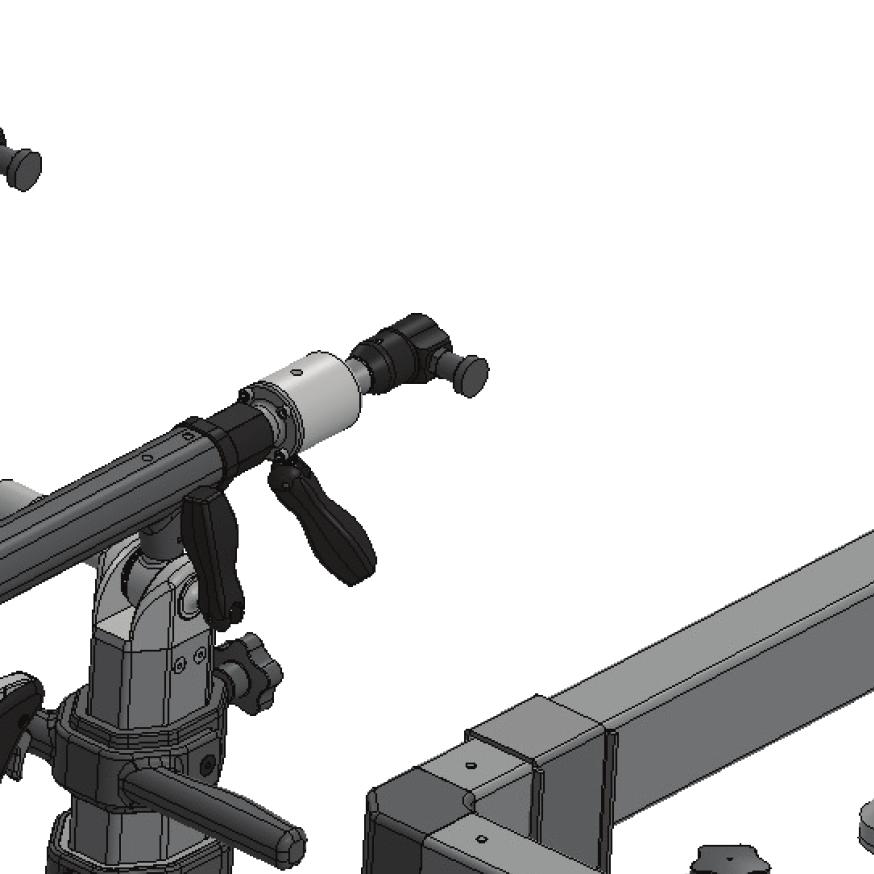
9 Fine-traction element Fine-Traction Element Controls 1 Crank-handle Increases or decreases traction. 2 Force indicator Gives an estimation of the force applied, as a reference. 3 Boot connector Connects the patient s boot to the fine-traction element. 4 Boot connector pin Secures or releases the patient s boot. 5 Internal/external rotation lever Rotates or secures the patient s foot. 7
10 Gross traction trigger handle controls Gross Traction Trigger Handle Controls 1 Trigger Allows movement to increase traction, decrease traction, or flex the patient s hip. 2 Button (red) Sets the hip distractor to glide mode (when used with the trigger), which allows the vertical spar to move freely. 3 Release button (gold) Allows middle section of the vertical spar to be raised or lowered. The gold release button has a gas-assisted spring action, propelling it up. Warning: Two hands should be used to operate the gross traction trigger handle. While one hand operates the trigger, the other hand should be used to control the movement of the vertical spar to prevent injury to the patient. 8
11 Base with base arms Base Controls 1 Foot pedal Retracts the wheels of the base with the red pedal. Lowers the wheels of the base with the green pedal so the base can be moved. 2 Lock-knob Secures the base arms to the base of the hip distractor. 3 Base arm plates with lever Aligns with the surgical table locks to secure the hip distractor frame to the surgical table. 4 Knob (at far end of base arm) Secures the base arm to the floor. Warning: The surgical table locks must be centered on the base arm plates and then locked down using the table s controls. Do not operate the hip distraction system unless the surgical table locks are properly positioned on the base arm plates. Operating the device when it is not properly secured may result in injury to the patient and may damage the device. 9
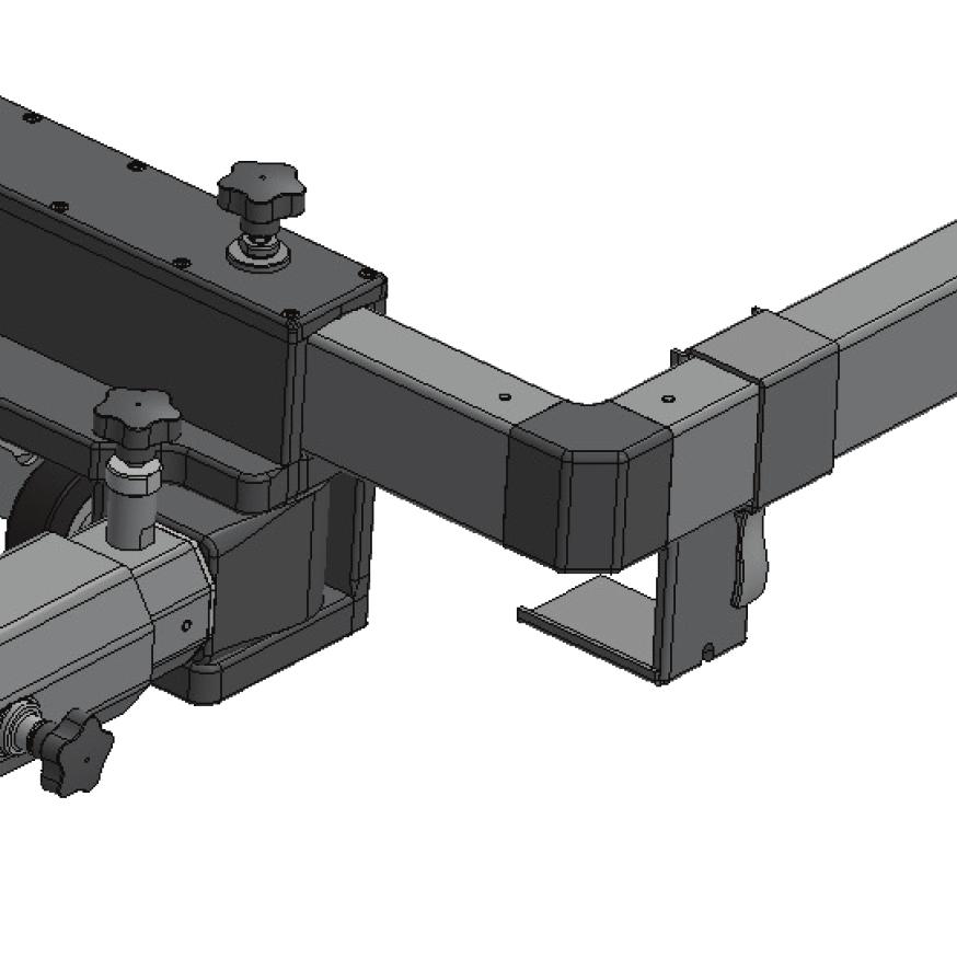
12 2.1.2 Accessories The Stryker Pivot Guardian Hip Distraction System has the following accessories. Tabletop extension with pad (part number ) Optional perineal post with pad (part number ) Tabletop Extension (with optional perineal post and pad attached) 1 Latch with turn-knob Slides onto surgical table rails and secures tabletop extension to surgical table. 2 Tabletop extension pad Attaches to tabletop extension. 3 Optional perineal post and pad Attaches to tabletop extension (as shown), if used. 4 Tabletop extension perineal post slots Allows the optional perineal post to be connected on the operative side. Note: The tabletop extension has an inclinometer on each side to indicate the angle of the surgical table when the patient is put in Trendelenburg position. 10
13 Pair of boots (part number ) Boot 1 Black tab Pulls the laces over the loop to fasten the boot. 2 Loop Holds the black tab and the laces to fasten the boot. 3 Boa knob Secures and loosens the boot. Push and turn to tighten. Pull to release. 4 Connection hole Attaches to the boot connector on the fine-traction element to secure the boot to the hip distractor. Patient Safety Kit, available in three sizes (part number , small; , medium; and , large). The Patient Safety Kit contains these single-use devices: Patient-positioning kit with strap Boot liners (either small, medium or large) Clear, sterile drape with Ioban TM 11
14 Storage bin Storage Bin 1 Perineal post with pad slot Holds the perineal post and pad. 2 Storage slot Holds tabletop extension, as shown. 3 Boot slot Holds the boot. 2.2 Surgical Table Compatibility Chart Use the Stryker Pivot Guardian Hip Distraction System only with compatible surgical tables. The Stryker Pivot Guardian Hip Distraction System is compatible with the following surgical tables. Compatible Surgical Tables Berchtold D-Series Skytron 3501C EZ Slide Skytron 3600B Ultraslide Skytron 6001* Skytron 6002* Skytron 6500 Skytron 6600 Steris 3080* Steris 3085* Steris
15 Compatible Surgical Tables Steris 5085 Trumpf Titan *Make sure surgical table is lowered completely. The minimum operating height is higher with this surgical table. 13
16 3 Intended Use The Stryker Pivot Guardian Hip Distraction System is intended for surgical distraction of the patient's hip and positioning of the lower limb in supine position. 14
17 4 Contraindications The use of this device is contraindicated when 1. a surgical procedure requiring distraction of the lower limb is not prescribed by an orthopedic surgeon. 2. a surgical procedure requires lateral positioning of the patient. 3. a hip arthroscopy procedure requires the direct anterior approach. 4. a patient s weight is in excess of 400 lbs (or kg). 5. a patient s height is outside the range of 4'10'' 6'10'' (or meters). 15
18 5 Cleaning and Disinfection Prior to each use of the device, the hip distractor frame and its reusable accessories need to be cleaned and disinfected. The hip distractor frame should be cleaned and disinfected in the most extended positions for all parts. Follow these instructions and use only recommended products for cleaning and disinfecting. 5.1 Cleaning After each use, please follow these instructions for cleaning the hip distractor frame and its reusable accessories. These instructions apply to the tabletop extension, the tabletop extension pad, the boots, the optional perineal post and pad (if used), and the hip distractor frame. 1. Use Alcohol Quaternary Ammonium * wipes to clean all surfaces. Caution: Use only Alcohol Quaternary Ammonium wipes for cleaning and disinfection. Alcohol Free Quaternary Ammonium wipes may damage the hip distractor frame or its accessories. 2. Wipe the external surfaces of the hip distractor frame and its accessories until all visible soil is removed. a. While wiping, give particular attention to crevices and hard-to-clean areas. b. Replace soiled wipes as needed and use additional wipes to ensure that all surfaces are uniformly cleaned. 3. In a well-lit area, from a distance of approximately 12 inches and with an unaided eye, visually inspect the hip distractor frame and its accessories for the absence or presence of remaining soil. While inspecting, give particular attention to verifying soil has been removed from the hard-to-clean areas (e.g., frame screws). If soil is present, then repeat the manual cleaning steps until all visible soil is removed. 5.2 Disinfection After each use, please follow these instructions for disinfecting the hip distractor frame and its accessories. These instructions apply to the tabletop extension, the tabletop extension pad, the boots, the optional perineal post and pad (if used), and the hip distractor frame. 1. Use Alcohol Quaternary Ammonium * wipes to clean all surfaces. 2. Thoroughly wipe the external surfaces of the hip distractor frame and its accessories and allow the surfaces to remain visibly wet for a minimum of two (2) minutes. a. During the two (2) minute contact time, use a disinfecting wipe to thoroughly wipe crevices and hard-to-disinfect areas. 16
19 b. If needed, use additional wipes to ensure all surfaces remain wet for the two (2) c. minute wet contact time. Let air dry. *Cleaning and Disinfection efficacy was validated with Super Sani-Cloth Germicidal Disposable Wipes. 17
20 6 Device Set up Set up the device by completing the following tasks sequentially: Transport the Device to the Surgical Area Remove the Storage Bin Attach the Hip Distractor Frame to the Surgical Table Adjust the Hip Distractor Frame for Surgeon Height Attach the Tabletop Extension Prepare the Fine-Traction Element Caution: Prior to each use of the Stryker Pivot Guardian Hip Distraction System, inspect all parts for damage that would affect the function of the device. Test each element of the device prior to use to make sure it is fully operational. Warning: The device and its reusable accessories must be cleaned and disinfected before each use. 18


21 6.1 Transport the Device to the Surgical Area 1. Transport the hip distractor frame to the room where it will be used. Caution: Make sure the base wheels and all horizontal spar wheels are unlocked before transporting the device. Exercise caution when transporting this device. Impact with another object may cause damage to the device. If an impact occurs, visually inspect the device for damage and make sure it is in working order. If the device is damaged or not working properly, do not use it. 6.2 Remove the Storage Bin 1. Remove the contents from the storage bin, setting them out of the way. 2. Lift the storage bin first from the base and then from the hip distractor frame. 3. Set the storage bin out of the way. 6.3 Attach the Hip Distractor Frame to the Surgical Table 1. Adjust the surgical table. a. Remove the foot section of the surgical table, if possible. If it cannot be removed, skip this step. b. Rotate the foot section down as far as possible. 19
22 c. Using the surgical table controls, raise the surgical table locks (unlock the surgical table). 2. Align the base of the hip distractor frame so it is centered in relation to the surgical table. Then push the base of the hip distractor frame as close to the surgical table as possible without them touching. Note: Make sure surgical table is raised high enough so that its foot section does not touch the base of the hip distractor frame. 3. Retract the wheels of the base by stepping on the red (inner) foot pedal of the base. 4. Remove and re-attach the base arms. a. Loosen the base arm lock-knob. b. Remove the base arm by sliding it out from the base. c. Flip the base arm so that the base arm plate is on the ground and the knob at the far end of the base arm faces up. d. Reinsert the base arm into the base of the hip distractor, clamping it up to the surgical table. e. Tighten the base arm lock-knob. 20
23 f. Repeat these steps for the second base arm. 5. Secure the hip distractor frame to the surgical table. Caution: Make sure the base wheels of the hip distractor frame have been retracted. Lowering the surgical table locks onto the base arm plates when the base wheels are deployed may damage the device. a. Lift the lever on the base arm plate. b. Slide the base arm plate to align it directly under the surgical table locks. Note: Each of the base arm plates must be aligned individually. c. Push the lever down to lock each base arm plate in place. 21
24 d. Using the surgical table s controls, lower the surgical table locks, ensuring that they rest completely on both of the base arm plates. Warning: The surgical table locks must be securely centered on the base arm plates. Do not operate the hip distraction system unless the surgical table locks are properly positioned on the base arm plates. Operating the device when it is not properly secured may result in injury to the patient and may damage the device. 6. Once the surgical table locks are properly positioned on the base arm plates, turn the knob on the far end of each base arm clockwise. a. Once the plunger side contacts the floor, give the knob three more full turns. b. Repeat this step for the second base arm. Caution: Do not turn this knob excessively as it may damage the device over time. Once the plunger side contacts the floor, only three more turns are needed to ensure the device will not slide along the floor. 22
25 6.4 Adjust the Hip Distractor Frame for Surgeon Height Note: The surgical table should be set to the appropriate height for the surgeon prior to using the hip distractor frame. 1. Extend the middle section of the vertical spar until the white line appears, or approximately 11 inches (28 centimeters). a. To extend the middle section, place one hand on the handle bar and one hand on the gross traction trigger handle. b. Push and hold the gold release button at the top of the gross traction trigger handle while controlling its movement with the other hand. Warning: When released, the middle section of the vertical spar may rise quickly. To avoid injury, do not put your head, chin or other body part above the fine-traction element or the vertical spar when pushing the gold release button. c. Release the gold release button when the proper height is reached. The white line should be visible just above the lower section of the vertical spar. d. Repeat these steps for the other vertical spar. 2. Extend the top section of the vertical spar. a. Holding the fine-traction element with one hand, loosen the turn-knob of the top section of the vertical spar. b. Raise the top section of the vertical spar until the fine-traction element is at the surgeon s shoulder height. 23
26 c. Tighten the turn-knob to secure the top section of the vertical spar. Once the top section is secured, release the fine-traction element. d. Repeat these steps for the other vertical spar. 6.5 Attach the Tabletop Extension The tabletop extension should be used only with compatible surgical tables. (See Section 2.2.) 1. Raise the latches on both sides of the tabletop extension. 2. Slide the tabletop extension onto the rails of the surgical table. Note: If the tabletop extension does not properly align with the rails of a compatible surgical table, contact your Stryker representative to make the proper adjustments. (See section 2.2 for list of compatible surgical tables.) 3. Slide the tabletop extension as far as possible along the surgical table s rails. 4. Press down on each latch so that they are flat against the rail. 24
27 5. Tighten the knobs on both sides of the tabletop extension. 6.6 Prepare the Fine-Traction Element 1. Fully extend each fine-traction element toward the surgical table by turning the fine traction crank-handle counterclockwise. Note: During the procedure, fine traction can only be added if the fine-traction element has been extended during set-up. 25
28 7 Patient Set up A Patient Safety Kit is required for each case. Have the appropriately-sized Patient Safety Kit ready for use. Note: The Patient Safety Kit is provided in three sizes (small, medium and large) based on the size of the patient s foot. Use the size chart affixed to the box of the Patient Safety Kit as a guide for selecting the correct size for the patient. The Patient Safety Kit contains the single-use devices for the patient: a pair of boot liners a patient-positioning kit consisting of a patient-positioning pad with a positioning strap a clear, sterile drape Warning: To prevent injury to the patient, the Stryker Pivot Guardian Hip Distraction System must be used in conjunction with the positioning pad and the boot liners in the Patient Safety Kit. Set up the patient by completing the following tasks sequentially: Secure the Patient-Positioning Pad Put the Boot Liners on the Patient Put the Boots on the Patient Position the Patient Put the Hip Distractor in Glide Mode Connect the Patient s Boots to the Device Put the Patient into Trendelenburg Position (Optional) Install the Perineal Post and Pad Adjust the Hip Distractor for Patient Height Drape the Device 26


. b.")


29 7.1 Secure the Patient-Positioning Pad This task may be completed prior to bringing the patient into the room. 1. Remove the patient-positioning kit from the Patient Safety Kit. 2. Place the positioning pad (blue side up) on the distal portion of the tabletop extension, aligning the semi-circle curve of the pad with the semi-circle curve of the tabletop extension. 3. Loop the distal straps of the positioning pad through the slots of the tabletop extension and secure them. 4. Loop the positioning pad s proximal straps around the rails of the surgical table and secure them tightly. 5. Attach the positioning strap. Note: The positioning strap comes in two parts that attach to opposite sides of the surgical table. Once a patient is on the surgical table, these two sides are joined like a seatbelt to prevent patient rolls or falls from the surgical table. a. Place one side of the positioning strap (blue side up) on the surgical table near the proximal strap (and between the proximal and distal straps). b. Take the plastic loop of the positioning strap around the outside of the table rail and pull it up on the inside of the table rail. c. Thread the Velcro end through the plastic loop of the positioning strap. d. Tighten by pushing the plastic loop back down toward the table rail. e. Repeat these steps with the other side of the positioning strap, attaching to the opposite side of the surgical table. 7.2 Put the Boot Liners on the Patient 1. If the patient is ambulatory, have the patient lie on the surgical table with his or her feet at the edge of the tabletop extension. Secure the position strap around the patient. If the patient is not ambulatory, put the boot liners on the patient while they are still on the gurney, starting with step 2. 27
30 Warning: Do not allow the patient to sit on the tabletop extension. The tabletop extension has a weight limit of 250 pounds (113.4 kg). Exceeding the weight limit may result in harm to the patient or damage to the tabletop extension. 2. Place the patient s heel into the center of one of the boot liners. Note: The boot liners are interchangeable: there is no left or right boot liner. Flexion of the knee can help to seat the heel or, if the leg is laying flat, tug on the top and bottom of the inner and outer boot liner to help seat the heel. The boot liners have four pairs of flaps that connect with Velcro. The two smaller (inner) pairs have foam cushioning. One of these smaller pairs wraps around the patient s foot and the other wraps just above the patient s ankle. The two larger, outer pairs of flaps wrap around the smaller ones. 3. Grab the topmost inner pair of flaps and pull each flap around the patient s ankle until the edges of foam cushioning meet each other, then secure the Velcro. Note: The inner, foam cushioned flaps do not need to be tight. It is much more important that the foam cushioning does not overlap. 4. Pull the second pair of inner flaps around the patient s foot until the edges of the foam cushioning meet, then secure the Velcro. Warning: Do not overlap the foam cushioning of the inner flaps, and do not leave a wide gap between the edges of the foam cushioning. Improperly securing the boot liner may result in unwanted pressure points for the patient. 5. Pull the smaller pair of outer flaps around the patient s foot and secure the Velcro, taking care to work out any folds or creases in the process. 28
31 6. Pull the last pair of outer flaps around the patient s calf and secure the Velcro, taking care to work out any folds or creases in the process. Warning: Inspect the boot liner to ensure there are no folds or creases, as these may cause unwanted pressure points. 7. Repeat these steps with the other foot. 7.3 Put the Boots on the Patient The boot liners must be put on the patient before putting on the boots. The top shell of the boot is connected to the boot with six black tabs. Each boot also has three Boa knobs that are pressed and turned to tighten the boot. When pulled out, the Boa knobs loosen automatically, without the need for turning. If the patient is not ambulatory, put the boots on the patient while the patient is on the gurney. Caution: Handle the boots carefully. Boots may break if dropped. 1. Open the boot by releasing the three black tabs on the lateral side of the boot. The other three black tabs should remain connected. Note: The boots are interchangeable: there is no left or right boot. Flexion of the knee can help to seat the heel of the patient into the heel of the boot. 29
32 2. Place the heel of the patient s wrapped foot into the heel of the boot. Make sure the heel is seated fully in the boot. 3. Pull the boot shell over the top of the patient s foot. 4. Attach the three black tabs. Ensuring there are no twists in the laces, pull each black tab over its loop to secure it. Note: The black tab should end up securely on the loop. To ensure proper fit, make sure the laces are not twisted. 5. Tighten the boot. a. Push each Boa knob down. b. Using the thumb and pointer finger, tighten all Boa knobs until they each feel tight to the fingers. Note: Do not tighten a Boa knob completely before moving to the next one. Instead, go back and forth between all three, tightening them as evenly as possible. c. Once all three Boa knobs have been tightened, give each Boa knob one or two more turns, as needed. Warning: Do not over-tighten the boots. The boots should be tight enough to hold a foot in place, but not so tight that they restrict circulation. Note: To loosen the boot at any point, pull up on the Boa knob. Do not turn the Boa knob to loosen. 6. Repeat these steps for the other boot. 7.4 Position the Patient Note: Follow facility patient-positioning procedures at all times. 1. Unstrap the positioning strap from the patient. 2. Slide the patient toward the hip distractor frame. If the patient was not ambulatory, transfer the patient from the gurney to the surgical table. 30
33 3. Position the operative hip on the lateral edge of the tabletop extension, just distal to the metal supports on the side of the tabletop extension. Warning: Ensure patient s bare back completely contacts the patient safety pad to reduce patient sliding when traction is pulled. 4. To reduce the risk of the patient rolling, angle the patient s head toward the nonoperative side of the surgical table. 5. Secure the patient again with the positioning strap. 7.5 Put the Hip Distractor in Glide Mode Glide mode allows the device to move freely. Putting the device in glide mode makes it easier to accomplish patient set-up activites. Glide mode is useful during the procedure, as well, to aid in increasing or decreasing gross traction and flexing the hip. To put the device into glide mode: 1. Depress and hold the red button on the trigger handle. 2. Pull the trigger Release the red button first, followed by the trigger. Note: The button will remain depressed and the trigger will stay in the pulled position. 4. Repeat these steps for the other vertical spar. Note: To take the one of the vertical spars out of glide mode, press the red button to reset the button and the trigger. The vertical spar will now be locked in its position. 31
34 7.6 Connect the Patient s Boots to the Device 1. Make sure the vertical spar is in glide mode so that it moves freely. 2. Slide the vertical spar close enough to the surgical table to connect the boots. 3. Connect the boot to the boot connector. a. Turn the internal/external rotation lever on the fine-traction element to loosen the boot connector. b. Support the patient s leg. c. Pull the metal pin of the boot connector located on the fine-traction element. d. Align the hole on the boot with the pin. e. Release the pin. Note: If properly aligned, no red will show on the sides of the pin. If red shows, pull the pin and realign the boot. f. Secure the boot connector in place by turning the internal/external rotation lever to tighten it. 4. Repeat these steps for the second boot. Note: Although only one side will be pulling traction, both boots must be secured. 32
35 7.7 Put the Patient into the Trendelenburg Position Warning: To avoid injury to the patient when putting him or her into the Tredelenburg position, make sure the vertical spar is in glide mode and that the internal/ external rotation lever on the boot connect is loosened. Note: If using the optional perineal post, see instructions for installing the perineal post and pad (section 7.8). When using the perineal post, this step may be skipped but is still recommended. 1. Make sure each vertical spar is in glide mode. 2. Put the patient in Trendelenburg position, with an angle of 10. Note: The tabletop extension has a guide (an inclinometer) affixed to its side to help visually estimate the angle. An angle of up to 15 of Tredelenburg may be needed for patients who are harder to distract. Tilting the table 1 2 degrees to the contra-lateral (non-operative) side may also be helpful for patients who are harder to distract 33
36 7.8 (Optional) Install the Perineal Post and Pad At the surgeon s discretion, a perineal post may be used with the Stryker Pivot Guardian Hip Distractor. Except where noted, all other set-up and operational instructions apply. Note: If Trendelenburg positioning is used, the perineal post and pad are not necessary. 1. Make sure approximately 5 inches (13 cm) of the perineal post extends from the bottom of the pad so it can be inserted into the tabletop extension. 2. Insert the perineal post into the tabletop extension, using the hole that is on the operative side. 3. Make sure each vertical spar is in glide mode. 4. Position the patient on the surgical table so that his or her upper thigh rests against the perineal post pad. Warning: When using the perineal post, limit the time that the patient is in traction to no more than 90 minutes. Excessive traction duration may result in harm to the patient. 34
37 7.9 Adjust the Hip Distractor for Patient Height The patient should be properly positioned for the procedure before the device is adjusted for the patient s height. Also, each vertical spar should be in glide mode and each internal/external rotation lever on the boot connector should be loosened. Note: In addition to following facility patient-positioning procedures, adjusting the hip distractor frame for the patient s height requires one person to manipulate the hip distractor frame while another person supports the patient s leg. 1. Loosen the knob on the side of the horizontal spar until the horizontal spar extends easily. Note: Make sure the abduction locks on both horizontal spars are unlocked. If either abduction lock is locked, step on the foot pedal of the horizontal spar to release it. 2. While one person supports the patient s leg, slide the vertical spar to the starting zone, aligning the white arrow on the vertical spar with the white arrow on the horizontal spar. 35
38 3. Push the red button on the trigger handle to lock the vertical spar in place (and take it out of glide mode). 4. Extend the horizontal spar. a. Pull back on the locked vertical spar to extend the horizontal spar until there is no more flexion in the patient s knees and the proper hip flexion has been achieved. 36
39 b. Secure the horizontal spar by tightening the knob on the side of the horizontal spar. 5. Step on the foot pedal (abduction lock) of the horizontal spar to secure the horizontal spar. 37
40 6. Repeat these steps for the patient s other leg Drape the Device Warning: The drape provided contains iodine. Do not use this drape if the patient is allergic to iodine. Caution: For use of the drape, follow the instructions provided with the drape. 1. Affix the drape to the patient per the drape s instructions. (After the procedure, remove the drape from the patient per the drape s instructions.) 2. Pull the upper portion of the drape over the patient s head and attach it per facility practices. 3. Pull the lower portion of the drape over the fine-traction elements of the hip distractor frame. Note: Some of the hip distractor frame s controls may then be accessed from the sterile field through the top of the drape. All functions of the hip distractor frame can be performed from outside of the sterile field by accessing controls under the drape or beyond the drape s reach. 38
41 8 Intra procedure Use of the Hip Distractor During the procedure, the hip distractor can be used to perform various tasks, including increasing or decreasing gross traction and fine traction, abducting and adducting, rotating the foot internally or externally, and flexing the hip. 8.1 Pull Gross Traction 1. To increase gross traction, put the vertical spar into glide mode. 2. Using two hands, pull the vertical spar away from the patient using smooth, controlled movement. Warning: To avoid injury to the patient, do not pull gross traction too quickly or farther than needed. 3. When appropriate traction is achieved, press the red button to lock the vertical spar in place. 8.2 Increase or Decrease Fine Traction Warning: To avoid injury, do not increase or decrease fine traction too quickly. Increase and decrease fine traction with slow, controlled movements. 1. To increase fine traction, turn the fine traction crank-handle clockwise. 2. To decrease fine traction, turn the fine traction crank-handle counterclockwise. Note: The fine-traction element has a force indicator to help estimate the amount of traction applied. Use it only as a reference. It should not be used to guide the application of traction force. 8.3 Decrease Gross Traction Warning: To avoid injury to the patient, always first decrease fine traction before decreasing gross traction. 1. Hold the handle firmly to secure the device. 2. Put the device in glide mode. 3. Guide the vertical spar toward the patient with smooth, controlled movements. Warning: Make sure you have control of the device to ensure smooth movement. To avoid injury to patient, decrease gross traction slowly. 39
42 4. When appropriate traction is achieved, press the red button to lock the vertical spar in place. 8.4 Abduct and Adduct 1. Step on the foot pedal of the horizontal spar to release the abduction lock. 2. Slide the horizontal spar outward or inward until the proper position is reached. 3. Step on the foot pedal of the horizontal spar to lock the abduction lock. 8.5 Rotate the Foot Internally or Externally 1. Support the patient s foot while turning the internal/external rotation lever (on the fine-traction element). 2. Rotate the foot internally or externally. Warning: To avoid injury to the patient, do not rotate the foot too quickly. Use slow, controlled movements. 3. To secure the foot in the chosen position, turn the internal/external rotation lever to tighten it. 40
43 8.6 Flex the Hip The hip can be flexed in two ways: 1. Flex the hip by moving the vertical spar along the horizontal spar. a. Put the vertical spar in glide mode. b. Loosen the internal/external rotation lever of the boot connector. c. Guide the vertical spar toward the patient. Note: To lock the vertical spar in place, press the red button. 2. Flex the hip by moving the middle section of the vertical spar up and down. a. Put the vertical spar in glide mode. Warning: To avoid injury to the patient when raising the middle section of the vertical spar, the device should be in glide mode and the internal/external rotation lever should be loosened. b. To extend the middle section, place one hand on the handle bar and one hand on the gross traction trigger handle. c. Push and hold the gold release button at the top of the gross traction trigger handle while controlling its movement with the other hand. Warning: When released, the middle section of the vertical spar may rise quickly. To avoid injury, do not put your head, chin or other body part above the fine-traction element or the vertical spar when pushing the gold release button. 41
44 9 Post Op Procedures Post-Op procedures include removing the boots and boot liners from the patient, disposing of all single-use devices, as well as all the tasks necessary to prepare the device for storage and to store it away. 9.1 Remove the Boots and Boot Liners Caution: Handle the boots carefully. Boots may break if dropped. 1. Put the device in glide mode so the device can move freely. 2. Loosen the internal/external rotation lever of the boot connector. 3. Move the vertical spar toward the surgical table. 4. Make sure one person is supporting the patient s leg. 5. Pull the metal pin of the boot connector (located on the fine-traction element) to release the boot. 6. While holding the pin, pull the boot out of the boot connector. 7. Pull up on the Boa knobs to loosen the boots. 8. One at a time, release each of the three black tabs on the lateral side of the boot to open the shell. Note: Do not release all six tabs on the boot. Release only the three on the lateral side of the boot. 9. Gently free the patient s foot from the boot. 10. Undo the Velcro on the boot liners to remove them. 11. Repeat these steps for the other foot. 9.2 Dispose of Single-Use Devices After the procedure, throw away all disposable devices per facility regulations. The disposable, single-use devices include the boot liners, the patient-positioning pad and positioning straps, and the drape. 42
45 9.3 Prepare the Device for Storage Collapse the device while it is still attached to the surgical table, as this takes less effort than collaspsing it after it has been detached from the surgical table. Note: The hip distractor frame and its reusable accessories must be cleaned and disinfected before being transported for storage. The hip distractor frame should be cleaned and disinfected in the most extended positions for all parts. Warning: When collapsing the device, be careful not to pinch or smash fingers in the moving parts. 1. Lower the vertical spar. a. Press the gold release button on the top of the gross traction trigger handle and push the middle section of the vertical spar down using the handle bar on the vertical spar. b. Loosen the knob for the top section of the vertical spar to lower the top section. c. Lower the top section of the vertical spar by pushing down on the side of the finetraction element where the boot connects. Note: The top section of the vertical spar is tapered, so it will not fully retract unless the knob is loosened sufficiently. d. Repeat these steps for second vertical spar. 2. Retract the horizontal spar. a. Loosen the knob on the side of the horizontal spar. b. Step on the abduction lock to release the brakes of the horizontal spar. c. Make sure the vertical spar is locked in place. d. Collapse the extension of the horizontal spar by pushing the vertical spar toward the surgical table. Note: The extension of the horizontal spar is tapered, so it will not fully retract unless the knob is loosened sufficiently. e. Tighten the knob on the side of the horizontal spar so that the extension of the horizontal spar stays in place. f. Repeat these steps for the second horizontal spar Remove the Base from the Surgical Table 1. Turn the knob at the far end of base counterclockwise until its plunger side if off the ground. 2. Using the surgical table controls, raise the surgical table locks to unlock the surgical table. 3. Remove the base arms from the base and invert them to reattach.. a. Loosen the knob on the top of the base. b. Slide the base arm out. c. Flip the base arm so that it is both upside down and facing away from the surgical table. 43
46 d. Slide the short end of the base arm back into the base. e. Tighten the knob on the top of the base to secure the base arm in this inverted position. f. Repeat these steps for the other base arm. 4. Step on the outer (green) foot pedal of the base to lower its wheels. 5. Unlock the abduction locks on the horizontal spars. 6. Using the trigger handles of the vertical spars, pull the hip distractor frame away from the surgical table Attach the Storage Bin to the Hip Distractor Frame 1. Step on the green pedal of the base to engage the wheels. Note: The wheels on the base cannot be lowered once the storage bin is attached. 2. After collasping the device and inverting the base arms, put the storage bin on the hip distractor frame. a. Abduct the horizontal spars. b. Put the vertical spars in glide mode. c. Place the front end of the storage bin onto the base, aligning the hole in the storage bin with the peg on the base. d. Move each vertical spar until its base is under the storage bin. e. Lock each vertical spar in place by pressing the red button. f. Adduct the horizontal spars until they are parallel and the storage bin comes to rest securely on them. 3. Load the storage bin. a. Put the boots into their storage slots. b. If applicable, put the perineal post and pad into the storage bin Remove the Tabletop Extension from the Surgical Table Note: Lock the surgical table using the surgical table controls before removing the tabletop extension. 1. Loosen the knobs on both sides of the tabletop extension. 2. Raise the latches on both sides of the tabletop extension. 3. Slide the tabletop extension away from the surgical table. 4. Place the tabletop extension into the storage bin. 44
47 9.4 Store the Device Once the storage bin is properly attached and loaded, the device may be moved for storage. 1. Transport device to its storage area. Caution: Make sure the base wheels and all horizontal spar wheels are unlocked before transporting the device. Exercise caution when transporting this device. Impact with another object may cause damage to the device. If an impact occurs, visually inspect the device for damage and make sure it is in working order. If the device is damaged or not working properly, do not use it. Note: Store the device in a dry, secure location. 45
48 10 Technical Specifications Weight 254 lbs. (115 kg.) Dimensions (collapsed for storage) Length x Width x Height: 52 x 24 x 44 (132 cm x 61 cm x 112 cm) Weight Limitations System supports patients up to 400 pounds or kilograms. Tabletop extension supports direct weight up to 250 pounds or kilograms. Height Limitations Expected Service Life System supports patients from 4 10 to 6 10 (1.47 to 2.08 meters) 4 years 46
49 11 Symbol Definitions This product and its labeling contain symbols that provide important information for the safe and proper use of the device. These symbols are defined below. Catalog number Lot number Serial number Date of manufacture Legal manufacturer Consult instructions for use Warning/Caution: see instructions for use Federal (USA) law restricts this device to sale by or on the order of a physician. Complies with the requirements of directive 93/42/EEC Authorized representative in Europe Quantity Made In U.S.A. Do not resterilize Do not reuse Do not use if package is damaged Turn clockwise Pinch point Do not sit 47
50 Move the lever or knob in the direction indicated to lock Move the lever in direction indicated to unlock 48
51
52 Produced For: Stryker Endoscopy 5900 Optical Court San Jose, CA USA U.S. Patents: patents Stryker Corporation or its divisions or other corporate affiliated entities own, use or have applied for the following trademarks or service marks: the Stryker Logo. All other trademarks are trademarks of their respective owners or holders. 2017/12 WCR: C.3 P35387 C
USER MANUAL Rev. 1.15
 QUANTUM QSP 7 TM BEACH CHAIR SHOULDER POSITIONER (BCP) USER MANUAL Rev. 1.15 Please read all the following instructions carefully to ensure proper functionality and to avoid injury or damage to your device.
Owner s Manual WARNING
 Owner s Manual Max User Height: 6 6 (198 cm) Max User Weight: 300 lbs (136 kg) Congratulations on the purchase of your InvertAlign Inversion Table Should you have any questions about the equipment, call
The Exercise Wheelchair
 NeuroGym Technologies Inc. The Exercise Wheelchair Product Manual NeuroGym Technologies Inc. 2012 1644 Bank Street, Suite 103 Ottawa, Ontario, Canada K1V 7Y6 Toll Free: 1-877-523=4148 www.neurogymtech.com
SelectTech 3.1 Bench Assembly / Owner s Manual
 SelectTech 3.1 Bench Assembly / Owner s Manual This product is compliant with the applicable CE requirements. Congratulations on your commitment to fitness and your purchase of the Bowflex SelectTech 3.1
SelectTech 4.1 Bench Assembly / Owner s Manual
 SelectTech 4.1 Bench Assembly / Owner s Manual This product is compliant with the applicable CE requirements. Table of Contents Important Safety Instructions...3 Safety Warning Labels and Serial Number...4
SaeboMAS (Patent Pending)
") SaeboMAS (Patent Pending) Product Manual Maximizing Function While Improving Proximal Strength No Plateau In Sight Introduction SaeboMAS dynamic mobile arm support system is a zero gravity upper extremity
SaeboMAS (Patent Pending) Product Manual Maximizing Function While Improving Proximal Strength No Plateau In Sight Introduction SaeboMAS dynamic mobile arm support system is a zero gravity upper extremity
VISTA400 REMOVABLE FOOT PLATE. Instructions For Use. Step on yellow pedals to close and open legs to go around chairs & ambulate.
 VISTA400 Instructions For Use Squeeze the yellow bar & push down/pull up to activate pneumatic stand assist. Step on yellow pedals to close and open legs to go around chairs & ambulate. Pull yellow levers
SelectTech 4.1 Bench. Assembly Manual
 SelectTech 4.1 Bench Assembly Manual Table of Contents Important Safety Instructions...3 Safety Warning Labels and Serial Number...4 Specifications...5 Before Assembly...5 Parts...6 Hardware...7 Tools...7
USER MANUAL CAUTION. MADE IN CHINA 2015 Body Action Enterprise Co., Ltd. All rights reserved.
 USER MANUAL CAUTION MADE IN CHINA 05 Body Action Enterprise Co., Ltd. All rights reserved. READ ALL PRECAUTIONS AND INSTRUCTIONS IN THIS MANUAL BEFORE USING THIS EQUIPMENT AND KEEP THIS FOR FUTURE REFERENCE
The RehabStation. User Manual
 The RehabStation User Manual www.med-mizer.com *Patent Pending 1 TABLE OF CONTENTS 1. Important General Safety Guidelines.3 2. General Use and Features 4 3. Use of Safety Ropes and Harness System..7 4.
weight.detach/bench ITEM NO: 76310
 weight.detach/bench ITEM NO: 76310 OWNER S MANUAL IMPORTANT: Read all instructions carefully before using this product. Retain this owner s manual for future reference. The specifications of this product
SAFETY LABELS CAUTION: PINCH POINT. Make sure locking pin is fully engaged before beginning forward and side lift exercises.
 CONTENTS 3 Important Safety Information 4 Assembly Instructions 6 Adjusting the Seat 6 Getting On and Off the Ab Coaster Pro 7 Ab Coaster Pro Exercises a. Forward Lift b. Side Lift (Obliques) c. Free-Style
Sunny Magnetic Exercise SF-B910
 Sunny Magnetic Exercise SF-B910 Bike IMPORTANT: PLEASE READ THIS MANUAL CAREFULLY BEFORE USING THE BIKE For Customer Service, please contact: support@sunnyhealthfitness.com Important Safety Information
 IMPORTANT: Please read and follow all instructions thoroughly before using your AB SHREDDER. Maximum user weight is 100 KG. KEEP BODY PARTS, HANDS AND FEET AWAY FROM THE SEAT, WHEELS AND THE CURVED TRACK
Multipower. User Guide E S S E N T I A L S T R E N G T H
 E L E M E N T E S S E N T I A L S T R E N G T H User Guide The identification plate of and manufacturer, affixed to the frame behind the barbell rack, gives the following details: A B C D E Name and address
Instructions for Use. For use with. 10 mg vial
 Instructions for Use For use with 10 mg vial Table of Contents Parts of the ZOMA-Jet 10... 1 Supplies you will need to mix a ZOMACTON 10 mg Vial... 2 Mix a ZOMACTON 10 mg vial... 3 Reset the ZOMA-Jet 10...
AcUMEDr. Arc Wrist Tower. For Wrist Arthroscopy And Fracture Reduction
 AcUMEDr Arc Wrist Tower For Wrist Arthroscopy And Fracture Reduction Arc Wrist Tower Since 1988, Acumed has been designing solutions to the demanding situations facing orthopaedic surgeons, hospitals and
IC031 Magnetic Belt Drive Performance Indoor Cycle Bike
 IC031 Magnetic Belt Drive Performance Indoor Cycle Bike USER MANUAL IMPORTANT: Read all instructions carefully before using this product. Retain owner s manual for future reference. For customer service,
CROSS TRAINING MAGNETIC TREADMILL
 CROSS TRAINING MAGNETIC TREADMILL SF-T7615 USER MANUAL IMPORTANT : Read all instructions carefully before using this product. Retain this manual for future reference. For customer service, contact support@sunnyhealthfitness.com
MX SELECT OWNER S MANUAL. Revolutionising Strength Training REGISTER YOUR PRODUCT AT MXSelect. MX_Select.
 MX SELECT OWNER S MANUAL Revolutionising Strength Training REGISTER YOUR PRODUCT AT WWW.MXSELECT.COM MXSelect MX_Select MX-Select MX SELECT WELCOME TO THE MX SELECT FAMILY Congratulations on your purchase
Read this while adjusting your Mirra. chair
 Read this while adjusting your Mirra chair Instructions on this card show all possible adjustments. Specific adjustments vary according to chair model. To view the Mirra chair user-adjustment video, visit
MANUAL THE EXERCISE WHEELCHAIR. Movement-Enabling Rehab Equipment
 Movement-Enabling Rehab Equipment MANUAL THE EXERCISE WHEELCHAIR Neurogym Technologies Inc. 2017 100-1050 Morrison Drive, Ottawa, ON, Canada neurogymtech.com ? FOR SERVICE OR PART INFORMATION CALL: + 1.877.523.4148
Technique Manual Technique Manual Rev. A 01/11/2011
 Technique Manual Technique Manual Table of Contents Introduction 4 Indications 5 Instrumentation 6 Frame Assembly 7 Position Guide 8-9 Tips and Tricks 10-13 Cleaning 14 Sterilization 14 Storage Instructions
PINK FOLDING RECUMBENT BIKE
 PINK FOLDING RECUMBENT BIKE SF-RB1117 USER MANUAL Read this manual carefully before using this product. Retain owner s manual for future reference. For Customer Service, please contact: support@sunnyhealthfitness.com
Owner s Manual & Exercise Guide
 Owner s Manual & Exercise Guide Distributed by: Thane International, Inc., La Quinta, CA 92253 Thane Direct Canada, Inc., Toronto, ON. Thane Direct UK Ltd., Admail 68, PL1 1AD w w w. t h a n e. c o m Copyright
IMPORTANT INFORMATION - PLEASE READ. Table of Contents. Introduction. General Information
 IMPORTANT INFORMATION - PLEASE READ Introduction Congratulations! Welcome to the world of the ELLIPTICAL CROSS TRAINER. The ELLIPTICAL CROSS TRAINER is one of the finest and most comprehensive pieces of
Low Row. User manual E S S E N T I A L S T R E N G T H
 E L E M E N T E S S E N T I A L S T R E N G T H User manual 1 The identification plate of and manufacturer, affixed on the back panel of the weight stack, gives the following details: A B C D E Name and
Congratulations on purchasing your new Total Gym
 TOTAL GYM ELITE OWNER S MANUAL Congratulations on purchasing your new Total Gym With this product in your home, you have everything you need to start your own workout program, to tone and strengthen the
Imola Lateral IBF System Surgical Technique
 Imola Lateral IBF System Surgical Technique IMOLA CIRCUIT TABLE OF CONTENTS Design Rationale Instructions for Use Surgical Technique 1. Table Mounting 2. Surgical Planning & Targeting 3. Access and Preparation
S E L E C T I O N. Adjustable Bench. User manual. All equipment T H E S T R E N G T H E V O L U T I O N
 S E L E C T I O N T H E S T R E N G T H E V O L U T I O N User manual All equipment 1 Contents Identification of the manufacturer and equipment... 3 Description of the equipment... 4 Technical data...
Product Information Packet Table of Contents. Introduction. Pit Shark Attachment. Attachment for Pendulum Rack. Introduction...
 Product Information Packet Table of Contents Pit Shark Attachment Attachment for Pendulum Rack Product Part Number: 410711 Introduction... Patent # 7871360 B1 1 General Safety Rules. 2 Symbols.... 3 Technical
Anterior Approach. Skills Stations
 Anterior Approach Skills Stations Anterior Approach Draping Option One Extra large drape Clear drape Step 1 Use a clear U drape (non sterile) around operative area and towards the foot. Tip: A towel wrapped
ASSEMBLY INSTRUCTIONS INSTRUCTIONAL TRAINING MANUAL DO NOT DISCARD - KEEP FOR FUTURE REFERENCE
 ASSEMBLY INSTRUCTIONS INSTRUCTIONAL TRAINING MANUAL DO NOT DISCARD - KEEP FOR FUTURE REFERENCE LD-1001 09/03-0 ASSEMBLY INSTRUCTIONS Before you begin: These instructions will guide you in properly assembling
The specifications of this product may vary from this photo and are subject to change without notice. For Customer Service, please contact:
 Elliptical Bike SF-E1114 The specifications of this product may vary from this photo and are subject to change without notice. For Customer Service, please contact: support@sunnyhealthfitness.com. Important
Take the leg press to the patient OWNER S MANUAL MADE IN U.S.A. PATENT NO. 6,042,523 MANUAL VERSION 2.0. Page 1
 Take the leg press to the patient OWNER S MANUAL MADE IN U.S.A. PATENT NO. 6,042,523 MANUAL VERSION 2.0 Page 1 Page 2 TABLE OF CONTENTS I. SHUTTLE MINIPRESS INTRO II. UNDERSTANDING YOUR SHUTTLE MINIPRESS
SUNNY MAGNETIC EXERCISE BIKE
 SUNNY MAGNETIC EXERCISE BIKE SF-B910 IMPORTANT! Please read the manual carefully before assembling and using the bike. For Customer Service, please contact: support@sunnyhealthfitness.com IMPORTANT SAFETY
Owner s Manual For maximum effectiveness and safety, please read this owner s manual and view the video before using your Total Gym 1100.
 Owner s Manual For maximum effectiveness and safety, please read this owner s manual and view the video before using your Total Gym 1100. TOTAL GYM 1100 OWNER S MANUAL Table of Contents EQUIPMENT / CAUTION
Quick Reference Guide
 Quick Reference Guide Quick Reference Guide Products for life from people who care. Page The Rifton Title TRAM Quick Reference Guide Contents Introduction 1 Importance of Proper Positioning 2 Key Components
MODEL# , Feb.
 INVERSION TABLE with Memory Foam OWNER S MANUAL MODEL#75164 2011, Feb. CAUTION: Weight on this product should not exceed 160kgs (350lbs). CAUTION: Exercise of a strenuous nature, as is customarily done
SP450 OWNER S MANUAL
 OWNER S MANUAL Product may vary slightly from the item pictured due to model upgrades Read all instructions carefully before using this product. Retain this owner s manual for future reference. NOTE: This
IMPORTANT SAFETY NOTICE:
 Dear Customer, Please read this instruction very carefully before using this item. You will find important information regarding safety of your magnetic bike. IMPORTANT SAFETY NOTICE: Note the following
USJ-875. Thank you for purchasing the USJ-875 SQUARE BIKE. Please read this manual carefully to ensure optimum performance and safety.
 USJ-875 Thank you for purchasing the USJ-875 SQUARE BIKE. Please read this manual carefully to ensure optimum performance and safety. CONTENTS IMPORTANT SAFETY INSTRUCTIONS...1 FEATURES...2 PART NAMES...3
SP150 OWNER S MANUAL Product may vary slightly from the item pictured due to model upgrades
 OWNER S MANUAL Product may vary slightly from the item pictured due to model upgrades Read all instructions carefully before using this product. Retain this owner s manual for future reference. TABLE OF
Thank you for purchasing the AB COASTER. Our customer service staff is ready to help and to answer any questions.
 Thank you for purchasing the AB COASTER. Our customer service staff is ready to help and to answer any questions. Our phone number is: 908-879-2713 The Ab Coaster Company, 173 Route 206, P.O. Box 9 Chester,
Great Legs are made here...
 Great ideas are born here... Great Legs are made here... Neil Summers, Award Winning Health Educator, Author & Inventor of the Best Selling Fitness Hit... LEG MASTER TOTAL BODY PLEASE READ THESE INSTRUCTIONS
ULTR A SERIES G7-S75
 ULTR A SERIES G7-S75 2 PROPER USAGE 1. Do not exceed weight limits of the exercise device. 2. If applicable, set safety stops to appropriate height. 3. If applicable, adjust seat pads, leg pads, foot pads,
Dedication to Quality
 P L A T I N U M Dedication to Quality We warrant this product to be free from all defects in material and workmanship when used according to the manufacturer s instructions. See Limited Warranty Card for
Free Wheelchair Mission. User Training Manual. We hope this chair makes life easier for you and gives you joy.
 Free Wheelchair Mission We hope this chair makes life easier for you and gives you joy. With Best Wishes, The Free Wheelchair Mission User Training Manual 4182014 31 32 NOTES Written by Kathryn Kumagai,
LESSON ASSIGNMENT. After completing this lesson, you should be able to:
 LESSON ASSIGNMENT LESSON 3 Traction Splints. LESSON ASSIGNMENT Paragraphs 3-1 through 3-5. LESSON OBJECTIVES After completing this lesson, you should be able to: 3-1. Identify the purpose of a traction
SAFETY LABELS CAUTION: PINCH POINT. Make sure locking pin is fully engaged before beginning forward and side lift exercises.
 CONTENTS 3 Important Safety Information 4 Assembly Instructions 6 Adjusting the Seat 6 Getting On and Off the Ab Coaster Max 7 Ab Coaster Max Exercises a. Forward Lift b. Side Lift (Obliques) c. Free-Style
USER'S MANUAL QUESTIONS?
 Model No. WL000 QUESTIONS? USER'S MANUAL As a manufacturer, we are committed to providing complete customer satisfaction. If you have questions or find that there are missing or damaged parts, we will
WEIGHT BENCH EXERCISER User s Manual
 Model No. 831.15964.1 Serial No. Write the serial number in the space above for reference. WEIGHT BENCH EXERCISER User s Manual Serial Number Decal (under frame) Assembly Operation Maintenance Part List
HealthCare International, Inc.
 Owner s Manual V.2 HealthCare International, Inc. 1 Table of Contents Safety Precautions... 3 Warranty Information... 4 Assembly Instructions... 5 Quick Tips... 8 AC Adaptor:... 8 Levelers:... 8 Seat Adjustments:...
The Bowflex Conquest Home Gym Assembly Instructions
 The Bowflex Conquest Home Gym Assembly Instructions P/N 001-6841 Rev C (04/2007) Table of Contents Before You Start... 2 Tools You Will Need / Hardware Chart... 3 Parts List... 4 Weight and Multi-carton
OWNER S MANUAL MODEL#75165
 INVERSION TABLE with Memory Foam OWNER S MANUAL MODEL#75165 2011, July CAUTION: Weight on this product should not exceed 136kgs (300lbs). CAUTION: Exercise of a strenuous nature, as is customarily done
HumaPen SAVVIO INSULIN DELIVERY DEVICE INSTRUCTIONS FOR USE
 HumaPen SAVVIO INSULIN DELIVERY DEVICE INSTRUCTIONS FOR USE For Single Patient Use Only www.lilly.ca INTRODUCTION HumaPen SAVVIO is designed for ease of use. You can give yourself multiple doses from one
ULTR A SERIES G7-S13
 ULTR A SERIES G7-S13 PROPER USAGE 1. Do not exceed weight limits of the exercise device.. If applicable, set safety stops to appropriate height. 3. If applicable, adjust seat pads, leg pads, foot pads,
POSITIONED FOR SUCCESS
 urgical olutions POITIOED FOR UCCE Advancing Care Through Practical Innovation TERI OT 1000 eries Orthopedic urgical Table One Integrated Approach to Healthcare EXPERIECE Fluid Motion The TERI OT 1000
Technique Guide. *smith&nephew SPEEDSCREW Fully Threaded Knotless Implant
 Technique Guide *smith&nephew SPEEDSCREW Fully Threaded Knotless Implant SPEEDSCREW system Fully threaded knotless implant system The SPEEDSCREW system is specifically designed for rotator cuff repair
KneeAlign System Surgical Technique Guide
 KneeAlign System Surgical Technique Guide Table of Contents Step 1 System Assembly... 1 Step 2 System Assembly... 2 Step 3 System Assembly... 2 Step 4 System Assembly... 2 Step 5 Sensor Pairing... 2 Step
Valencia Pedicle Screw Surgical Technique
 Valencia Pedicle Screw Surgical Technique VALENCIA CIRCUIT TABLE OF CONTENTS Design Rationale Indications for Use Surgical Technique 1. Pedicle Preparation 2. Screw Insertion 3. Rod Placement 4. Locking
ULTR A SERIES G7-S51
 ULTR A SERIES G7-S51 PROPER USAGE 1. Do not exceed weight limits of the exercise device.. If applicable, set safety stops to appropriate height. 3. If applicable, adjust seat pads, leg pads, foot pads,
PEN USER MANUAL Byetta 5 micrograms solution for injection in pre-filled pen (exenatide)
") PEN USER MANUAL Byetta 5 micrograms solution for injection in pre-filled pen (exenatide) Section 1. WHAT YOU NEED TO KNOW ABOUT YOUR BYETTA PEN Read this section completely before you begin. Then, move
PEN USER MANUAL Byetta 5 micrograms solution for injection in pre-filled pen (exenatide) Section 1. WHAT YOU NEED TO KNOW ABOUT YOUR BYETTA PEN Read this section completely before you begin. Then, move
Instructions for Use Neulasta (nu-las-tah) (pegfilgrastim) Injection, for subcutaneous use Single-Dose Prefilled Syringe. Plunger rod Used plunger rod
 (pegfilgrastim) Injection, for subcutaneous use Single-Dose Prefilled Syringe. Plunger rod Used plunger rod") Instructions for Use Neulasta (nu-las-tah) (pegfilgrastim) Injection, for subcutaneous use Single-Dose Prefilled Syringe Guide to parts Before use After use Plunger rod Used plunger rod Finger grip Label
Instructions for Use Neulasta (nu-las-tah) (pegfilgrastim) Injection, for subcutaneous use Single-Dose Prefilled Syringe Guide to parts Before use After use Plunger rod Used plunger rod Finger grip Label
Important Safety Instructions 1-2. Maintenance 3. Features 4. Assembly Parts List 5. Assembly Instructions 6-9. Console Operation 10
 Important Safety Instructions 1-2 Maintenance 3 Features 4 Assembly Parts List 5 Assembly Instructions 6-9 Console Operation 10 Moving Machine 12 Exercise Instructions 13-18 Exploded Drawing 19 Parts List
RSD SYSTEM. Owner s Manual
 RSD SYSTEM Owner s Manual RSD Parts Identification Diagram Index RSD Parts Identification Diagram Page 3 Cord Guide Page 4 Attaching the RSD Page 5 Attaching the Handle Page 6 Screw Cord Guide T-nut Handle
Owner s Manual. Model# IMPORTANT: Read all instructions carefully before using this product. Retain this owner s manual for future reference.
 Swing Stepper Owner s Manual Model#91306 IMPORTANT: Read all instructions carefully before using this product. Retain this owner s manual for future reference. The specifications of this product may vary
1. Abs Triangle of Control Muscle: Upper abdominals Resistance: Body weight Body Connection: Legs
 Program C1 Chest and Shoulders 1. Abs Muscle: Upper abdominals Resistance: Body weight Lie flat with legs hooked through upper bench, adjusted so that the knees and hips are at 90 degrees. Extend arms
Owner s Manual. For maximum effectiveness and safety, please read this owner s manual and view the video before using your Total Gym Platinum Plus.
 Owner s Manual For maximum effectiveness and safety, please read this owner s manual and view the video before using your Total Gym Platinum Plus. TOTAL GYM PLATINUM PLUS OWNER S MANUAL Congratulations
Thank you for purchasing the AB COASTER. Our customer service staff is ready to help and to answer any questions.
 Thank you for purchasing the AB COASTER. Our customer service staff is ready to help and to answer any questions. Our phone number is: 908-879-2713 The Ab Coaster Company, 173 Route 206, P.O. Box 9 Chester,
Power-Pak 445 Adjustable Dumbbell System
 Power-Pak 445 djustable Dumbbell System ssembly / Owner s Manual This product is compliant with the applicable CE requirements. To validate warranty support, keep the original proof of purchase and record
OWNER S MANUAL. BODYCRAFT 7699 Green Meadows Dr., Lewis Center, Ohio Tel:
 OWNER S MANUAL BODYCRAFT 7699 Green Meadows Dr., Lewis Center, Ohio 43035 Tel: 800.990.5556 1 www.bodycraft.com SAFETY INSTRUCTION WARNING: To reduce the risk of serious injury, read the following safety
Snow Angels on Foam Roll
 Thoracic Mobilization on Foam Roll Lie on your back with a foam roller positioned horizontally across your mid back, and arms crossed in front of your body. Bend your knees so your feet are resting flat
OWNER S MANUAL. Gravity Model 5402
 OWNER S MANUAL Gravity 4000 Model 5402 The specifications of this product may vary from this photo and are subject to change without notice. IRONMAN, IRONMAN TRIATHLON and M-DOT are registeved trademarks
Single Use Curlew TM Multiple Biopsy Forceps
 Single Use Curlew TM Multiple Biopsy Forceps 13 SPECIMEN WITH METAL STORAGE CYLINDER With In Situ Fixation, Batch or Single Specimen Collection US Patents 5,782,747; 5,980,468; 6,071,248; foreign patents
USER S MANUAL QUESTIONS? CAUTION. For a great selection of new CD and MP3 workouts. Visit our website at. or call
 Model No. RBBE950 Serial No. Write the serial number in the space above for future reference. USER S MANUAL Serial Number Decal (Under Seat) QUESTIONS? As a manufacturer, we are committed to providing
EB2 Exercise Bike. User Manual [Revision 1.0 February 2018]
![EB2 Exercise Bike. User Manual [Revision 1.0 February 2018]](/thumbs/92/110892811.jpg "EB2 Exercise Bike. User Manual [Revision 1.0 February 2018]") User Manual [Revision 1.0 February 2018] READ THIS MANUAL CAREFULLY BEFORE USE FAILURE TO DO SO MAY RESULT IN INJURY, PROPERTY DAMAGE AND MAY VOID WARRANTY. KEEP THIS MANUAL FOR FUTURE REFERENCE. Products
User Manual [Revision 1.0 February 2018] READ THIS MANUAL CAREFULLY BEFORE USE FAILURE TO DO SO MAY RESULT IN INJURY, PROPERTY DAMAGE AND MAY VOID WARRANTY. KEEP THIS MANUAL FOR FUTURE REFERENCE. Products
limbsandthings.com Advanced Catheterisation Trainer User Guide For more skills training products visit Limbs & Things Ltd.
 Advanced Catheterisation Trainer Product No: 60150 User Guide For more skills training products visit limbsandthings.com Limbs & Things Ltd. Sussex Street, St Philips Bristol, BS2 0RA, UK sales@limbsandthings.com
 www.fitnessfirst-usa.com Chest Fly Shoulders, elbows and wrists aligned in same plane with elbows at 90 degrees Feet should be staggered, and body leaning slightly forward for leverage Step far enough
Contents. Safety and Precautions Practical Exercise Tips...8. Information for Healthcare Professionals...9. Installation Instructions:
 2 4 Contents Safety and Precautions...6-7 Practical Exercise Tips...8 Information for Healthcare Professionals...9 Installation Instructions: U-Bar Installation...10 Resistance Bungee Installation...11
HumaPen LUXURA HD INSULIN DELIVERY DEVICE INSTRUCTIONS FOR USE
 1 HumaPen LUXURA HD INSULIN DELIVERY DEVICE INSTRUCTIONS FOR USE For use only with Lilly 3 ml insulin cartridges (100 units/ml). Do not use other brands of insulin cartridges. The color of your HumaPen
CIRCULATORY MASSAGER OPERA TING INSTRUCTION HM01-08QI
 BLOOD CIRCULATORY MASSAGER OPERA TING INSTRUCTION HM01-08QI 1 Blood Circulatory Massager Thanks for you purchase our machine of Blood Circulatory Massager. Please read this manual carefully before using
Standing Shoulder Internal Rotation with Anchored Resistance. Shoulder External Rotation Reactive Isometrics
 Standing Shoulder Row with Anchored Resistance Begin standing upright, holding both ends of a resistance band that is anchored in front of you at chest height, with your palms facing inward. Pull your
ULTR A SERIES G7-S23
 ULTR A SERIES G7-S3 PROPER USAGE 1. Do not exceed weight limits of the exercise device.. If applicable, set safety stops to appropriate height. 3. If applicable, adjust seat pads, leg pads, foot pads,
Advanced Catheterisation Trainer User Guide
 Advanced Catheterisation Trainer User Guide Also for Advanced Male Catheterisation Trainer Part No: 605 Advanced Female Catheterisation Trainer Part No: 6055 Designed and manufactured by Limbs & Things
Body Bar FLEX. Exercises for the Core and Abdominals. by Gordon L. Brown, Jr. for Body Bar, Inc.
 Body Bar FLEX Exercises for the Core and Abdominals by Gordon L. Brown, Jr. for Body Bar, Inc. 1 Exercises for the Core and Abdominals This presentation features stretching and strengthening exercises
Patient Lifter (Hydraulic Lift) Information for the Patient A Guide for Patients in the Home
 Information for the Patient A Guide for Patients in the Home") Patient Lifter (Hydraulic Lift) Information for the Patient A Guide for Patients in the Home Table of Contents Chapter 1... 1 Patient Lift (Hydraulic Lift)... 1 What you should expect?... 1 Chapter 2...2-9
Patient Lifter (Hydraulic Lift) Information for the Patient A Guide for Patients in the Home Table of Contents Chapter 1... 1 Patient Lift (Hydraulic Lift)... 1 What you should expect?... 1 Chapter 2...2-9
Instructions for Use Enbrel (en-brel) (etanercept) injection, for subcutaneous use Single-dose Prefilled Syringe
 (etanercept) injection, for subcutaneous use Single-dose Prefilled Syringe") Instructions for Use Enbrel (en-brel) (etanercept) injection, for subcutaneous use Single-dose Prefilled Syringe How do I prepare and give an injection with Enbrel Single-dose Prefilled Syringe? There
Instructions for Use Enbrel (en-brel) (etanercept) injection, for subcutaneous use Single-dose Prefilled Syringe How do I prepare and give an injection with Enbrel Single-dose Prefilled Syringe? There
OWNER S MANUAL and INSTALLATION INSTRUCTIONS
 NP-L5003 Ab Crunch OWNER S MANUAL and INSTALLATION INSTRUCTIONS Leverage Ab Crunch Owner s Manual Copyright 2017. Core Health and Fitness, LLC. All rights reserved, including those to reproduce this book
Cybex Weight Machine Manual
 Cybex Weight Machine Manual Note: Machine adjustments are indicated by a yellow knob or lever. Feel free to ask our staff for guidance. Lower Body Leg Press - Adjust the back rest to a comfortable position.
DEEP TISSUE FOAM ROLLER MASSAGE GUIDE
 Recover, Recharge, & Renew your body and mind with RE by Empower. Soothe everyday aches & pains; reduce tension & stress; and improve your overall health. DEEP TISSUE FOAM ROLLER MASSAGE GUIDE Three phases
Stratis INSTRUCTIONS FOR USE. Needle-free Injection System. 0.5mL volume (+/-5%)
") Stratis Needle-free Injection System INSTRUCTIONS FOR USE 0.5mL volume (+/-5%) Stratis English Symbols Glossary (Note: All symbols are derived from ISO 15223-1, Medical Devices - Symbols to be used with
Stratis Needle-free Injection System INSTRUCTIONS FOR USE 0.5mL volume (+/-5%) Stratis English Symbols Glossary (Note: All symbols are derived from ISO 15223-1, Medical Devices - Symbols to be used with
Zimmer NexGen MIS Tibial Component. Cemented Surgical Technique IMAGE TO COME
 Zimmer NexGen MIS Tibial Component Cemented Surgical Technique IMAGE TO COME Zimmer NexGen MIS Tibial Component Cemented Surgical Technique 1 Zimmer NexGen MIS Tibial Component Cemented Surgical Technique
M.I.S. MAKE IT SMART IN ONE SYSTEM. Surgical Technique. Hip Knee Spine Navigation
 M.I.S. MAKE IT SMART IN ONE SYSTEM Surgical Technique Hip Knee Spine Navigation M.U.S.T. Mini Open Surgical Technique Hip Knee Spine Navigation 2 C O N T E N T S 1 INTRODUCTION 4 2 SURGICAL TECHNIQUE 5
EXERCISE INSTRUCTIONS
 EXERCISE INSTRUCTIONS A/ Strength A01 SQUAT Stand on the Power-Plate with feet shoulder width apart. Keeping the back straight and knees slightly bent, gently squeeze the leg muscles. You should feel tension
USER MANUAL - EN. IN 5729 Exercise Bike insportline Xbike
 USER MANUAL - EN IN 579 Exercise Bike insportline Xbike CONTENT IMPORTANT SAFETY PRECAUTIONS... 3 CHECK LIST (CONTACT PACKAGE)... 4 VIEW... 6 ASSEMBLY INSTRUCTION... 6 EXPLODED VIEW... 0 PARTS LIST...
USER S MANUAL QUESTIONS? CAUTION. Visit our website at.
 Model No. NTCCBE950 Serial No. Write the serial number in the space above for future reference. USER S MANUAL Serial Number Decal (under seat) QUESTIONS? As a manufacturer, we are committed to providing