Small Fragment Plating System. Securing optimal fixation through locked and compression plating technology
|
|
|
- Dortha Wood
- 5 years ago
- Views:
Transcription

1 Small Fragment Plating System Securing optimal fixation through locked and compression plating technology
2
3 Contents Design Rationale Introduction Interfragmentary Fixation Insertion of a 3.5 mm Cortical Screw Insertion of a 4.0 mm Cancellous Lag Screw Insertion of a 4.0 mm Cannulated Cancellous Screw Plate Selection Plate Insertion Neutral Insertion of a 3.5 mm Non-Locking Cortical Screw in a Compression Slot Dynamic Compression/Eccentric Insertion of a 3.5 mm Non-Locking Cortical Screw in a Compression Slot Insertion of a 3.5 mm Locking Cortical Screw or 4.0 mm Cancellous Screw in a Threaded Hole Insertion of a 3.5 mm Non-locking Cortical Screw in a Threaded Hole Insertion of a 4.0 mm Non-locking Cancellous Screw into any Plate Hole One-Third Tubular Plate Insertion Instrument Trays 18 1
4 2
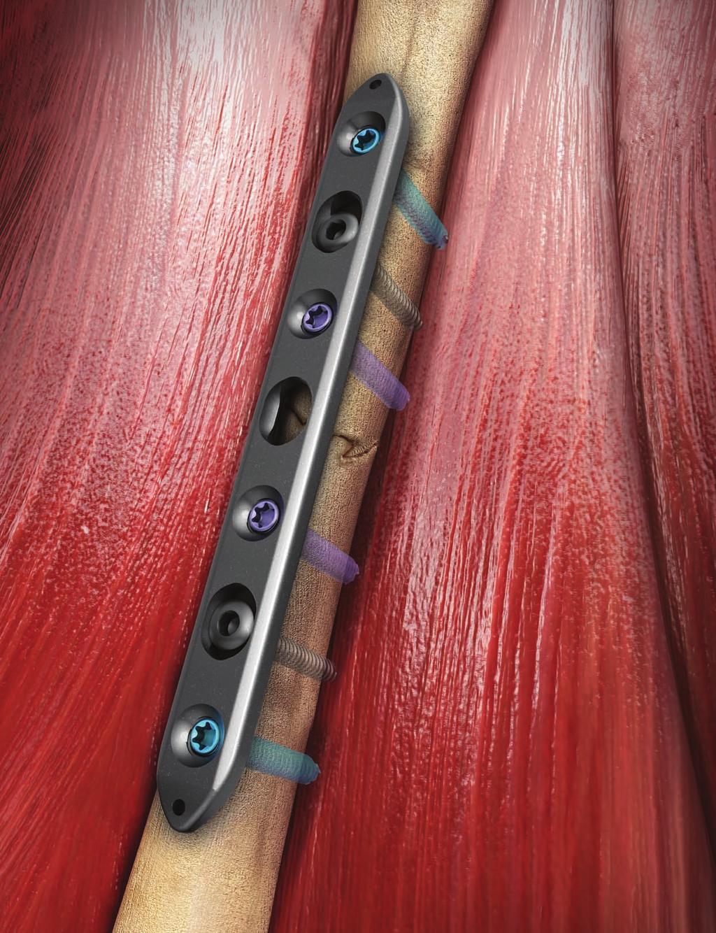
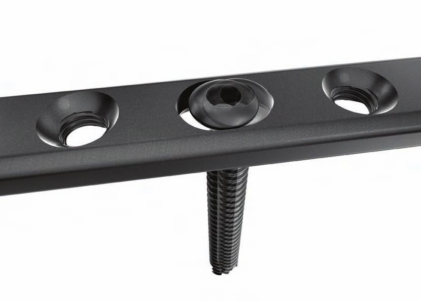
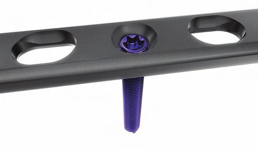
5 Hybrid plating technology for compression and locked fixation Compression screw fixation The oval screw hole can accept non-locking screws to allow for up to 64 degrees of axial and 34 degrees of transverse screw angulation while offering 3 mm of axial compression. The screws can be positioned and used in compression, neutral and buttress modes. Locked screw fixation The round threaded screw holes accept screws that will lock into position when tightened to establish a fixed angle construct for improved fixation in osteopenic bone or when optimal screw purchase is required. The DePuy Small Fragment System is a titanium plate and screw system that fuses locking screw technology with conventional plating techniques. The set was designed to maximize treatment options when managing fractures requiring small fragment fixation, as well as, to serve as the core system for additional anatomic implants. 3

6 Introduction The Small Fragment System combines our traditional system with the enhanced benefits of locking screw technology. The compression plate features two distinct plate hole designs, each serving an intended purpose without compromising performance. The hybrid construction of this plate offers the surgeon the ability to combine standard interfragmentary compression with the added stability of fixed angle locking. This construct will protect the compression and lag screws while providing stability across extensive comminution, unstable metaphyseal fractures or in osteopenic bone. Indications for Use: Fixation of fractures, osteotomies, nonunions of the: fibula olecranon distal humerus radius ulna distal tibia clavicle System Contents: 3.5 mm locking compression plates One-third tubular plates, non-locking 16 mm, 20 mm and 25 mm spider washers 3.5 mm cortical screws, locking 3.5 mm cortical screws, non-locking 4.0 mm cancellous screws, locking 4.0 mm cancellous lag screws, non-locking 4.0 mm cancellous screws, full thread, non-locking 4.0 mm cannulated cancellous lag screws, non-locking Optional: 2.7 mm cortical screws, non-locking 4

7 3.5 mm Locking Cortical Screw: Larger core diameter and shallower thread pitch for improved bending and shear strength compared to a standard 3.5 mm cortical screw Self-tapping tip minimizes the need for pre-tapping and eases screw insertion T-15 drive Features: 3.5 mm Locking Compression Plate: Uniform hole spacing Compression, neutral and buttress screw positions Threaded holes for locking screw option 64 degrees of axial screw angulation 34 degrees of transverse screw angulation 3 mm of compression Bullet-shaped ends for submuscular plate insertion 5 14 holes Tapered screw head helps ensure alignment of the screw head into the plate hole Tapered threaded head minimizes screw back-out and construct pullout Available in lengths of mm 4.0 mm Locking Cancellous Screw: Self-tapping tip minimizes the need for pre-tapping and eases screw insertion T-15 drive Tapered screw head helps ensure alignment of the screw head into the plate hole Tapered threaded head minimizes screw back-out and construct pullout Available in lengths of mm 5


8 Interfragmentary Fixation Interfragmentary Fixation Interfragmentary fixation uses lag screws (Figure 1) to apply compression across the fracture surface. Intra-articular and epiphyseal fractures are frequent indications for interfragmentary fixation. Figure 1 To apply compression across the fracture site, the screw threads must engage only the far fragment. If the screw threads engage the near cortex, the fracture will be distracted, and compression will not be possible. The 3.5 mm cortical screws are generally selected for use in diaphyseal bone. The 4.0 mm cancellous bone screws are generally used in metaphyseal or osteopenic bone (Figure 2). Figure 2 6
 (Figure 3).")
9 3.5 mm Cortical Screws (Cat. No XX) Reduce the fracture and maintain the reduction with bone forceps. Drill a gliding hole in the near cortex with the 3.5 mm Drill Bit (Cat. No ) using the 2.5/3.5 mm Drill Guide (Cat. No ) (Figure 3). Figure 3 Figure 4 Note: For oblique fractures, guide the drill bit so it bisects the angle between a line perpendicular to the plane of the fracture and a line perpendicular to the axis of the bone. Insert the 2.5 mm drill guide into the glide hole. Drill a pilot hole into the far cortex with the 2.5 mm Drill Bit (Cat. No ) (Figure 4). Drill near cortex with the 3.5 mm drill bit Drill far cortex with the 2.5 mm drill bit Figure 5 Note: If necessary, prepare the near cortex with the Countersink (Cat. No ) to allow the screw head to sit flush on the cortical surface (Figure 5). Use countersink as necessary Determine the required screw length by taking a direct reading from the NON-L line on the Small Fragment Depth Gauge (Cat. No ) (Figure 6). Figure 6 Figure 7 Note: In hard or dense bone, tap the pilot hole in the far cortex with the 3.5 mm Cortical Tap (Cat. No ) prior to attempting to insert the screw. The 2.5/3.5 mm drill guide can be used as a tissue protector. Insert the appropriate length 3.5 mm Cortical Screw (Cat. No XX) by hand or with power using the Screw Holder Sleeve (Cat. No ) over the 2.5 mm Hex Driver (Cat. No ) in the Ratchet Handle (Cat. No ) or drill (Figure 7). Always perform final seating of the screw by hand. Take depth reading from NON-L line Insert the 3.5 mm cortical screw using the 2.5 mm hex driver 7
 perpendicular to the plane of the fracture using the 2.9/4.0 mm Drill Guide (Cat. No. 2141-29-400).")
.")
10 Interfragmentary Fixation Figure mm Cancellous Lag Screws (Cat. no XX) Reduce the fracture and maintain the reduction with bone forceps. Drill both cortices with the 2.9 mm Drill Bit (Cat. No ) perpendicular to the plane of the fracture using the 2.9/4.0 mm Drill Guide (Cat. No ). Advance the drill across the fracture site to the required depth, confirming the position with image intensification (Figure 8). Drill perpendicular to the fracture plane with the 2.9 mm drill bit Figure 9 Determine the required screw length by taking a direct reading from the NON-L line on the Small Fragment Depth Gauge (Figure 9). Take depth reading from NON-L line Figure 10 Insert the appropiate length 4.0 mm Cancellous Lag Screw (Cat. No XX) by hand or with power using the screw holder sleeve over the 2.5 mm hex driver in the ratchet handle or drill. Always perform final seating of the screw by hand (Figure 10). Figure 11 Note: In soft cancellous bone, the use of the Flat (Cat. No ) or Cupped Washer (Cat. No ), may prevent the screw head from sinking into the near cortex and allow better compression across the fracture site (Figure 11). Insert the 4. 0 mm cancellous screw using the 2.5 mm hex driver 8
. Advance the K-wire across the fracture site to the required depth, confirming the position with image intensification (Figure 12).")
.")
. Care should be taken to avoid drilling the far cortex as the K-wire will loosen. Place the selected self-drilling, self-tapping 4.")
11 4.0 mm Cannulated Cancellous Screws (Cat. No XX) Reduce the fracture and maintain the reduction with bone forceps. Insert a 1.6 mm x 6 in. K-wire (Cat. No or ) perpendicular to the plane of the fracture using the 1.6/2.9 mm Drill Guide (Cat. No ). Advance the K-wire across the fracture site to the required depth, confirming the position with image intensification (Figure 12). Figure 13 Figure 12 Insert a 1.6 mm K-wire across the fracture Place the K-wire Depth Gauge (Cat. No ) over the K-wire and hold firmly against the bone. Read the required screw length directly off the gauge at the end of the K-wire (Figure 13). Take depth reading from the end of the K-wire Note: In dense bone, it may be necessary to pre-drill the near cortex and screw path with the 2.9 mm Cannulated Drill Bit (Cat. No ) using the 1.6/2.9 mm drill guide (Figure 14). Care should be taken to avoid drilling the far cortex as the K-wire will loosen. Place the selected self-drilling, self-tapping 4.0 mm Cannulated Cancellous Screw (Cat. No XX) over the K-wire and insert by hand or with power using the Cannulated Hex Driver (Cat. No ) in the ratchet handle or drill. Perform final seating of the screw by hand. Remove the K-wire (Figure 15). In soft bone, the use of the flat or cupped washer may prevent the screw head from sinking into the near cortex and allow better compression across the fracture site. Caution: Cannulated screwdrivers should always be used over a K-wire. Figure 15 Figure 14 Pre-drill the near cortex with the 2.9 mm cannulated drill bit in dense bone Insert the 4.0 mm cannulated screw using the 2.5 mm cannulated hex driver 9
 Plate Selection: A plate should be selected that has a minimum of three screw holes in each main fracture fragment.")

, the plate must be slightly pre-bent to assure compression of the far cortex and avoid fracture gapping.")


12 Plate Selection Locking Compression Plate (Cat. No XX) Plate Selection: A plate should be selected that has a minimum of three screw holes in each main fracture fragment. Longer plates are generally recommended, as this will increase the working length of the plate. Screw holes are an option for screw placement, not a requirement. Screws should, however, be placed in the holes nearest the fracture and at the ends of the plate. Typically, non-locked screws are used for interfragmentary compression and to bring the plate down to the near cortex, with locked screws placed in selected, as well as terminal screw holes. When straight plates are used on straight bones (e.g. ulna), the plate must be slightly pre-bent to assure compression of the far cortex and avoid fracture gapping. Note: Bending should occur between the plate holes and not through any threaded holes. Reduction and Temporary Placement: Position the center of the plate over the fracture site and hold in place with plate bone forceps or the provisional fixation pins. Use of the Provisional Fixation Pin (Cat. No /1) Avoid placing the provisional fixation pin in a screw hole that will be needed immediately for implant fixation. The selfdrilling pin has quick connect for power insertion. Advance the pin slowly until the shoulder of the pin contacts the plate and pulls it down to the bone. Advancing the pin beyond that point may result in stripping of the threads. Figure 16 Use of the Plate Bone Forceps (Cat. No ) Slide the serrated foot of one limb of the clamp onto the undersurface of the bone while inserting the protrusion of the other limb into a plate hole. The c shape of the clamp minimizes soft tissue damage (Figure 16). 10

 end of the 2.5 mm ACP Drill Guide (Cat. No. 8241-68-000) into the compression slot with the arrow pointed toward the fracture line (Figure 17).")
.")
13 Plate Insertion Screw Insertion: Determine the type of screw to be used: 3.5 mm locking cortical, 3.5 mm non-locking cortical, 4.0 mm locking cancellous or 4.0 mm non-locking cancellous. Any combination of screws can be used. If a combination of locking and nonlocking screws is used, a non-locking screw should be inserted first to pull the plate to the bone. 3.5 mm non-locking cortical screw 3.5 mm locking cortical screw 4.0 mm non-locking cancellous screw 4.0 mm locking cancellous screw Neutral Insertion of a 3.5 mm Non-Locking Cortical Screw in a Compression Slot Insert the neutral (green) end of the 2.5 mm ACP Drill Guide (Cat. No ) into the compression slot with the arrow pointed toward the fracture line (Figure 17). Drill through both cortices with the 2.5 mm drill bit. Figure 17 Drill with the 2.5 mm drill bit in the neutral position Measure the drilled hole with the small fragment depth gauge by taking a direct reading from the NON-L line (Figure 18). Figure 18 Insert the appropriate length 3.5 mm non-locking cortical screw with the screw holder sleeve over the 2.5 mm hex driver coupled to the ratchet handle (Figure 19). Take the depth reading from the NON-L line CAUTION: The arrow on the neutral (green) end of the 2.5 mm ACP Drill Guide must point toward the fracture site to ensure neutral screw placement. Figure 19 Insert the 3.5 mm non-locking cortical screw using the 2.5 mm hex driver 11
. Drill with the 2.")

14 Plate Insertion Figure 20 Dynamic Compression/Eccentric Insertion of a 3.5 mm Non-Locking Cortical Screw in a Compression Slot Insert the compression (gold) end of the 2.5 mm ACP drill guide into the compression slot with the arrow pointed toward the fracture line. Drill through both cortices with the 2.5 mm drill bit (Figure 20). Drill with the 2.5 mm drill bit in the eccentric position. Measure the drilled hole with the small fragment depth gauge by taking a direct reading from the NON-L line (Figure 21). Figure 21 Take the depth reading from the NON-L line Insert the appropriate length 3.5 mm non-locking cortical screw with the screw holder sleeve over the 2.5 mm hex driver coupled to the ratchet handle (Figure 22). Figure 22 CAUTION: The arrow on the compression end of the 2.5 mm ACP Drill Guide must point toward the fracture site to obtain compression. If the arrow is misdirected away from the fracture, distraction of the fracture will occur. Insert the 3.5 mm non-locking cortical screw using the 2.5 mm hex driver 12
 to the desired depth and read the depth measurement from the calibrated drill bit at the top of the drill guide (Figure 23).")
15 Insertion of a Locking Screw (3.5 mm Cortical Cat. No XX or 4.0 mm Cancellous Cat. No XX) in a Threaded Hole Screw the 2.7 mm Locking Drill Guide (Cat. No ) into a threaded plate hole until fully seated. Drill with the 2.7 mm Calibrated Drill Bit (Cat. No ) to the desired depth and read the depth measurement from the calibrated drill bit at the top of the drill guide (Figure 23). Remove the 2.7 mm locking drill guide. Figure 23 Drill with the 2.7 mm calibrated drill bit reading the depth from the top of the drill guide Note: If a second method of measurement is desired, measure the drilled hole by taking a direct reading from the Lock line on the small fragment depth gauge (Figure 24). Figure 24 Insert the selected locking screw with the T-15 Driver (Cat. No ) coupled to the 2.0 Nm Torque-Limiting Screwdriver Handle (Cat. No ) (Figure 25). Take the depth reading from the LOCK line Tip: Using a power screwdriver is not recommended for insertion of any locking screws. Perform all final screw tightening by hand with the torque-limiting screwdriver handle. Figure 25 Insert the locking screw using the T-15 driver on the torque-limiting handle 13

. Drill with the 2.5 mm drill bit through the 2.5/3.")

16 Plate Insertion Slide retractor along plate Plate End Retractor: The retractor is designed to retract soft tissue when accessing the terminal screw holes of the plate. Slide the rails of the retractor along the plate edges and then raise the handle toward the end of the incision, allowing the cutout to fit over the contoured end of the plate. Figure 26 Insertion of a 3.5 mm Non-locking Cortical Screw in a Threaded Hole Insert the 2.5 mm end of the 2.5/3.5 mm drill guide into the threaded hole and drill through both cortices with the 2.5 mm drill bit (Figure 26). Drill with the 2.5 mm drill bit through the 2.5/3.5 mm drill guide Measure the drilled hole by taking a direct reading from the NON-L line on the small fragment depth gauge (Figure 27). Figure 27 Figure 28 Take the depth reading from the NON-L line Insert the appropriate length 3.5 mm non-locking cortical screw with the screw holder sleeve over the 2.5 mm hex driver coupled to the ratchet handle (Figure 28). Insert the 3.5 mm non-locking cortical screw using the 2.5 mm hex driver 14
17 Insertion of a 4.0 mm Non-locking Cancellous Screw into any Plate Hole Insert the 2.9 mm end of the 2.9/4.0 mm drill guide into the plate hole and drill through both cortices with the 2.9 mm drill bit (Figure 29). Figure 29 Drill with the 2.9 mm drill bit through the 2.9/4.0 mm drill guide Measure the drilled hole by taking a direct reading from the NON-L line on the small fragment depth gauge (Figure 30). Figure 30 Insert the appropriate length 4.0 mm cancellous screw with the screw holder sleeve over the 2.5 mm hex driver coupled to the ratchet handle (Figure 31). Tip: A tap (for each screw type) is available for use in dense bone. Take the depth reading from the NON-L line Figure 31 Insert the 4.0 mm cancellous screw using the 2.5 mm hex driver 15


.")
18 Plate Insertion Figure 32 Drill with the 2.5 mm drill bit through the 2.5/3.5 mm drill guide One-Third Tubular Plate (Cat. No XX) The one-third tubular plate is 1.3 mm thick and may be useful in areas with minimal soft tissue coverage, such as the lateral malleolus, olecranon and distal end of the ulna. Note: It is recommended that the plate be long enough to allow screws to be placed through at least five or six cortices on either side of the fracture. If a longer plate is used, it is not necessary to fill every hole. The oval holes allow eccentric positioning of the screws, which can be used for axial compression of a fracture when the plate is applied as a tension band plate. The plate is contoured to the shape of the bone utilizing a bending template as a model. Figure 33 Take a direct reading from the NON-L line on the depth gauge The fracture is reduced and the plate is applied to the bone and held in place with reduction forceps. Using a screw hole near the fracture, drill a hole through both cortices with the 2.5 mm drill bit and the 2.5/3.5 mm drill guide (Figure 32). Measure the drilled hole by taking a direct reading from the NON-L line on the small fragment depth gauge (Figure 33). Figure 34 Select the appropriate length 3.5 mm cortical screw and insert with the screw holder sleeve over the 2.5 mm hex driver, but do not fully tighten (Figure 34). Insert the 3.5 mm non-locking cortical screw using the 2.5 mm hex driver 16
.")
19 In the screw hole near the fracture in the opposite fragment, place the 2.5 mm tip of the 2.5/3.5 mm drill guide in the eccentric position away from the fracture and drill through both cortices with the 2.5 mm drill bit (Figure 35). Measure the drilled hole by taking a direct reading from the NON-L line on the small fragment depth gauge and insert the selected 3.5 mm cortical screw. Tighten the first screw. Figure 35 Eccentrically place a screw on the opposite side of the fracture Add the remaining screws as determined by the fracture pattern. Perform final tightening of all screws (Figure 36). Note: A 4.0 mm cancellous screw can be used if the screw is used in cancellous bone. The 4.0 mm cancellous screws utilize a 2.9 mm drill bit, a 4.0 mm tap and corresponding drill guides and tissue protectors. Figure 36 The plate can also be applied as a neutralization plate in fractures with butterfly fragments or spiral components. After fracture reduction interfragmentary fixation with independent lag screws is performed to stabilize the fracture. The plate is then applied in neutral mode (no compression) using 3.5 mm cortical screws or 4.0 mm cancellous screws according to the bone type. 17

.")


20 Instrument Trays The small fragment case was designed to reflect the varied functional requirements of our customers. The system consists of two screw modules, one plate module and two instrument trays (Figure 37). The entire system can be housed in one large base or it can be split into a separate instrument and implant base. Figure 37 The trays contain three-dimensional graphics for rapid implant and instrument identification enhancing both surgical and processing efficiencies (Figure 38). Figure 38 The screw instruments are contained on an innovative flip tray that can be placed on the Mayo stand permitting rapid transition between the various screw types. Everything needed for implant insertion is at your fingertips (Figures 39). The screw instruments double sided flip tray Figure 39 18
21 Surgeon Design Team Roy Sanders, M.D. Chief, Department of Orthopaedics, Tampa General Hospital Director, Orthopaedic Trauma Services, Florida Orthopaedic Institute, Tampa, Florida George Haidukewych, M.D. Orthopaedic Trauma Service, Florida Orthopaedic Institute, Tampa General Hospital, Tampa, Florida David M. Huebner, M.D. Director of Orthopaedic Trauma, Good Samaritan Hospital, Kearney, Nebraska Michael Wich, M.D. Deputy Head, Department of Trauma and Orthopaedic Surgery, Unfallkrankenhaus Berlin, Berlin, Germany 19

22 Instrument Trays Small Fragment Screw Modules XX 2.7 mm Cortical Screws, Non-locking (Optional) mm in 2 mm increments mm in 5 mm increments XX 4.0 mm Cannulated Cancellous Screws Partial Thread, Non-locking mm in 2 mm increments mm in 5 mm increments XX 4.0 mm Cancellous Screws Full Thread, Non-locking mm in 2 mm increments mm in 5 mm increments XX 4.0 mm Cancellous Screws Partial Thread, Non-locking mm in 2 mm increments mm in 5 mm increments mm Spider Plate, Offset mm Spider Plate Flat Washer Cup Washer mm Spider Plate 20

23 1 2 3 Small Fragment Screw Modules XX 4.0 mm Cancellous Screws, Full Thread, Locking mm in 2 mm increments mm in 5 mm increments XX 3.5 mm Cortical Screws, Non-Locking mm in 2 mm increments mm in 5 mm increments XX 3.5 mm Cortical Screws, Locking mm in 2 mm increments mm in 5 mm increments 21

24 Instrument Trays Plate Module/Reduction Instrument Tray mm Locking Compression Plates Hole 72.6 mm Hole 85.6 mm Hole 98.6 mm Hole mm Hole mm Hole mm Hole mm Hole mm Profile: Width: 10.3 mm Thickness: 3.7 mm Distance between center of holes: 13 mm mm 100 Degree Tubular Plates Hole 25 mm Hole 37 mm Hole 49 mm Hole 61 mm Hole 73 mm Hole 85 mm Hole 97 mm Hole 109 mm Hole 121 mm Profile: Width: 9.2 mm Thickness: 1.3 mm Distance between center of holes: 11.4 mm Distance between central holes: 16 mm Plate Bending Irons, 2 each Reduction Forceps with Points, Large Small Frag Tensioner Small Plate/Bone Forceps Bending Templates, 2 each Reduction Forceps with Points, 2 each Reduction Forceps with Serrated Jaws, 2 each Sharp Hook 22

25 Instrument Trays Screw Instrument Tray Screw Forceps Cannulated Ratchet Handle mm Hex Screwdriver, 2 each T-15 Screwdriver, 2 each Nm Torque-Limiting Handle Bent Hohmann Retractors, 2 each Cobra Hohmann Retractors, 2 each Plate End Retractor Screw Holder Sleeve Fixation Pin, 26 mm, 2 each Fixation Pin, 12 mm, 2 each 23

26 Instrument Trays Flip Tray - Side Periosteal Elevator Depth Gauge /2.7 mm Drill Guide mm Drill Bit, 2 each mm Cortical Tap, 2 each mm ACP Drill Guide mm Drill Bit, 2 each mm Drill Bit, 2 each mm Cortical Tap, 2 each /3.5 mm Drill Guide Countersink mm Locking Cortical Tap, 2 each mm Calibrated Drill Bit, 2 each mm Locking Drill Guides 24

27 Instrument Trays Flip Tray - Side Depth Gauge K-Wire Depth Gauge /4.0 mm Drill Guide mm Drill Bit, 2 each mm Drill Bit, 2 each mm Cancellous Tap, 2 each Easy Out /2.9 mm Drill Guide mm Cannulated Drill Bit, 2 each mm Cannulated Tap, 2 each Cannulated Screwdriver, 2 each Cannulated Countersink mm Threaded Tip K-Wires, 6 each mm K-Wires, 12 each 25
28
29
30 Important: This Essential Product Information does not include all of the information necessary for selection and use of a device. Please see full labeling for all necessary information. Indications: The use of bone plates and screws provides the orthopaedic surgeon a means of bone fixation and helps generally in the management of fractures and reconstructive surgeries. These implants are intended as a guide to normal healing, and are NOT intended to replace normal body structure or bear the weight of the body in the presence of incomplete bone healing. Delayed unions or nonunions in the presence of load bearing or weight bearing might eventually cause the implant to break due to metal fatigue. All metal surgical implants are subjected to repeated stress in use, which can result in metal fatigue. Contraindications: Active infection Conditions which tend to retard healing such as blood supply limitations, previous infections, insufficient quantity or quality of bone to permit stabilization of the fracture complex Conditions that restrict the patient s ability or willingness to follow postoperative instructions during the healing process Foreign body sensitivity Cases where the implant(s) would cross open epiphyseal plates in skeletally immature patients Cases with malignant primary or metastatic tumors which preclude adequate bone support or screw fixations, unless supplemental fixation or stabilization methods are utilized Warnings and Precautions: Bone screws and plates are intended for partial weight bearing and non-weight bearing applications. These components cannot be expected to withstand the unsupported stresses of full weight bearing. Adverse Events: The following are the most frequent adverse events after fixation with orthopaedic plates and screws: loosening, bending, cracking or fracture of the components or loss of fixation in bone attributable to nonunion, osteoporosis, markedly unstable comminuted fractures; loss of anatomic position with nonunion or malunion with rotation or angulation; infection and allergies and adverse reactions to the device material. 0M DePuy Orthopaedics, Inc. 700 Orthopaedic Drive Warsaw, IN USA Tel: +1 (800) Fax: +1 (574) DePuy International Ltd St Anthony s Road Leeds LS11 8DT England Tel: +44 (0) Fax: +44 (0) Printed in USA DePuy Orthopaedics, Inc. All rights reserved.
Small Fragment Plating System
 Small Fragment Plating System Securing optimal fixation through locked and compression plating technology SURGICAL TECHNIQUE RECOVERY FUNCTION SURVIVORSHIP DePuy believes in an approach to trauma surgery
SMV Scientific Bone Plate and Screw System Surgical Technique
 SMV Scientific Bone Plate and Screw System Surgical Technique Description: The SMV Scientific Bone Plate and Screw System consists of non-locking plates and bone screw fasteners in a variety of lengths,
Technique Guide. Small Fragment Locking Compression Plate (LCP) System. Stainless steel and titanium.
 System. Stainless steel and titanium.") Technique Guide Small Fragment Locking Compression Plate (LCP) System. Stainless steel and titanium. Table of Contents Introduction Small Fragment Locking Compression Plate (LCP) System 2 AO Principles
Technique Guide Small Fragment Locking Compression Plate (LCP) System. Stainless steel and titanium. Table of Contents Introduction Small Fragment Locking Compression Plate (LCP) System 2 AO Principles
Surgical Technique. Anterolateral and Medial Distal Tibia Locking Plates
 Surgical Technique Anterolateral and Medial Distal Tibia Locking Plates PERI-LOC Periarticular Locked Plating System Anterolateral and Medial Distal Tibia Locking Plates Surgical Technique Contents Product
Small Fragment Locking Compression Plate (LCP ) System
 System") Stainless Steel and Titanium Small Fragment Locking Compression Plate (LCP ) System Surgical Technique Table of Contents Introduction Small Fragment Locking Compression Plate (LCP) System 2 AO Principles
Stainless Steel and Titanium Small Fragment Locking Compression Plate (LCP ) System Surgical Technique Table of Contents Introduction Small Fragment Locking Compression Plate (LCP) System 2 AO Principles
Surgical Technique. 3.5mm and 4.5mm Lateral Proximal Tibia Locking Plates
 Surgical Technique 3.5mm and 4.5mm Lateral Proximal Tibia Locking Plates PERI-LOC Periarticular Locked Plating System 3.5mm and 4.5mm Lateral Proximal Tibia Locking Plate Surgical Technique Contents Product
Zimmer Small Fragment Universal Locking System. Surgical Technique
 Zimmer Small Fragment Universal Locking System Surgical Technique Zimmer Small Fragment Universal Locking System 1 Zimmer Small Fragment Universal Locking System Surgical Technique Table of Contents Introduction
Surgical Technique. Locking Small Fragment Overview
 Surgical Technique Locking Small Fragment Overview PERI-LOC Locked Plating System Locking Small Fragment Overview Surgical Technique Table of contents Product overview... 2 Introduction... 2 Indications...
COMPACT ANKLE FRACTURE SYSTEM
 COMPACT ANKLE FRACTURE SYSTEM Consolidated ankle fracture solution for surgery centers SURGICAL TECHNIQUE TABLE OF CONTENTS INTRODUCTION Compact Ankle Fracture System 2 AO Principles 8 Indications 9 Clinical
Technique Guide. Small Fragment Locking Compression Plate (LCP) System. Stainless Steel and Titanium.
 System. Stainless Steel and Titanium.") Technique Guide Small Fragment Locking Compression Plate (LCP) System. Stainless Steel and Titanium. Table of Contents Introduction Small Fragment Locking Compression Plate (LCP) System 2 AO Principles
Technique Guide Small Fragment Locking Compression Plate (LCP) System. Stainless Steel and Titanium. Table of Contents Introduction Small Fragment Locking Compression Plate (LCP) System 2 AO Principles
Surgical Technique. Lower Extremity Plates and Straight Plates
 Surgical Technique Lower Extremity Plates and Straight Plates 2 Table of contents Overview...4 Indications... 4 Contraindications... 4 Screw Options... 5 Straight Plate Options... 6 Proximal Tibia Plate
LCP Medial Distal Tibia Plate, without Tab. The Low Profile Anatomic Fixation System with Angular Stability and Optimal Screw Orientation.
 LCP Medial Distal Tibia Plate, without Tab. The Low Profile Anatomic Fixation System with Angular Stability and Optimal Screw Orientation. Technique Guide LCP Small Fragment System Table of Contents Introduction
Technique Guide. 3.5 mm LCP Low Bend Medial Distal Tibia Plates. Part of the Synthes locking compression plate (LCP) system.
 system.") Technique Guide 3.5 mm LCP Low Bend Medial Distal Tibia Plates. Part of the Synthes locking compression plate (LCP) system. Table of Contents Introduction 3.5 mm LCP Low Bend Medial Distal Tibia Plates
Technique Guide 3.5 mm LCP Low Bend Medial Distal Tibia Plates. Part of the Synthes locking compression plate (LCP) system. Table of Contents Introduction 3.5 mm LCP Low Bend Medial Distal Tibia Plates
Locking Ankle Plating System. Surgical Technique
 Locking Ankle Plating System Surgical Technique Acumed is a global leader of innovative orthopaedic and medical solutions. We are dedicated to developing products, service methods, and approaches that
A locking plate system that expands a surgeon s options in trauma surgery. Zimmer NCB Plating System
 A locking plate system that expands a surgeon s options in trauma surgery Zimmer NCB Plating System The Power of Choice The power of having true intraoperative options is at your fingertips. Using standard
Surgical Technique. Proximal Humerus Locking Plate
 Surgical Technique Proximal Humerus Locking Plate PERI-LOC Upper Extremity Locked Plating System 3.5mm & 4.5mm Proximal Humerus Locking PlatesCatalog Infor Table of Contents Introduction.........................................................2
Surgical Technique. Targeter Systems Overview
 Surgical Technique Targeter Systems Overview PERI-LOC Locked Plating System Targeter Systems Overview Table of contents Product overview... 2 Introduction... 2 Indications... 2 Design features and benefits...
A locking plate system that expands a surgeon s options in trauma surgery. Zimmer NCB Plating System
 A locking plate system that expands a surgeon s options in trauma surgery Zimmer NCB Plating System The Power of Choice The power of having true intraoperative options is at your fingertips. Using standard
WINSTA-C. Clavicle Plating System
 Clavicle Plating System Clinical Advisor Michael Kurer FRCS FRCS (Orth) Consultant Orthopaedic and Shoulder Surgeon North Middlesex University Hospital NHS Trust Table of Contents Introduction Indication
LCP Medial Proximal Tibial Plate 4.5/5.0. Part of the Synthes LCP periarticular plating system.
 LCP Medial Proximal Tibial Plate 4.5/5.0. Part of the Synthes LCP periarticular plating system. Technique Guide This publication is not intended for distribution in the USA. Instruments and implants approved
3. Insert Tocar Sleeves Insert the NCB tissue protection sleeve assembly 1.6 to 10mm through a skin incision (Fig. 38).
.") NCB Proximal Humerus Plating System Surgical Technique 19 2. Temporary Plate Fixation The plate can be temporary fixed to the bone with 1.6mm K-wire through the proximal cannulated fixation screw of the
NCB Proximal Humerus Plating System Surgical Technique 19 2. Temporary Plate Fixation The plate can be temporary fixed to the bone with 1.6mm K-wire through the proximal cannulated fixation screw of the
Technique Guide. 3.5 mm LCP Low Bend Medial Distal Tibia Plate Aiming Instruments. Part of the 3.5 mm LCP Percutaneous Instrument System.
 Technique Guide 3.5 mm LCP Low Bend Medial Distal Tibia Plate Aiming Instruments. Part of the 3.5 mm LCP Percutaneous Instrument System. Table of Contents Introduction 3.5 mm LCP Low Bend Medial Distal
Zimmer Small Fragment Universal Locking System
 Zimmer Small Fragment Universal Locking System Surgical Technique Flexibility and compatibility in one system Zimmer Small Fragment Universal Locking System Zimmer Small Fragment Universal Locking System
Surgical Technique. Distal Humerus Locking Plate
 Surgical Technique Distal Humerus Locking Plate PERI-LOC Locked Plating System Distal Humerus Locking Plate Surgical Technique Table of Contents Introduction...2 Indications...3 Plate Features...3 Patient
Surgical Technique International Version
 Surgical Technique International Version PERI-LOC VLP Variable-Angle Locked Plating System Surgical Technique Table of Contents Product Overview...2 Introduction...2 Indications and Contraindications...3
LCP Medial Proximal Tibial Plate 3.5. Part of the Synthes small fragment Locking Compression Plate (LCP) system.
 system.") LCP Medial Proximal Tibial Plate 3.5. Part of the Synthes small fragment Locking Compression Plate (LCP) system. Technique Guide This publication is not intended for distribution in the USA. Instruments
LCP Medial Proximal Tibial Plate 3.5. Part of the Synthes small fragment Locking Compression Plate (LCP) system. Technique Guide This publication is not intended for distribution in the USA. Instruments
Technique Guide. 3.5 mm LCP Olecranon Plates. Part of the Synthes locking compression plate (LCP) system.
 system.") Technique Guide 3.5 mm LCP Olecranon Plates. Part of the Synthes locking compression plate (LCP) system. Table of Contents Introduction 3.5 mm LCP Olecranon Plates 2 AO Principles 3 Indications 3 Clinical
Technique Guide 3.5 mm LCP Olecranon Plates. Part of the Synthes locking compression plate (LCP) system. Table of Contents Introduction 3.5 mm LCP Olecranon Plates 2 AO Principles 3 Indications 3 Clinical
Distal Ulnar Locking Plate
 INDEX Indications Patient Position Surgical Technique - Step 1 Approach - Step 2 Plate Contouring - Step 3 Fracture Reduction - Step 4 Distal Plate Fixation - Step 5 Confirm Proper Reconstruction - Step
A.L.P.S. Distal Tibia Plating System. Surgical Technique
 A.L.P.S. Distal Tibia Plating System Surgical Technique One Surgeon. One Patient. Over 1 million times per year, Biomet helps one surgeon provide personalized care to one patient. The science and art of
Surgical Technique. Calcaneal Locking Plate
 Surgical Technique Calcaneal Locking Plate PERI-LOC Locked Plating System Calcaneal Locking Plate Surgical TechniqueCatalog Infor Table of Contents Introduction...2 Indications...3 Plate Features...3 Patient
Surgical Technique. Clavicle Locking Plate
 Surgical Technique Clavicle Locking Plate PERI-LOC Locked Plating System Clavicle Locking Plate Surgical Technique Table of Contents Introduction...2 Indications...3 Plate Features...3 Patient Positioning...4
Ankle Fixation System. System Brochure
 Ankle Fixation System System Brochure Anatomy Fracture Implant Transverse Ankle Hook Plate Semi-Tubular Plate Oblique Sidewinder Plate Semi-Tubular Plate Fibula Comminuted Semi-Tubular Plate Transverse
Surgical Technique. Cannulated Angled Blade Plate 3.5 and 4.5, 90
 Surgical Technique Cannulated Angled Blade Plate 3.5 and 4.5, 90 Cannulated Angled Blade Plate 3.5 and 4.5, 90 Table of contents Indications/Contraindications 2 Implants 3 Surgical technique 5 Implant
OBSOLETED. LCP Medial Distal Tibia Plate, without Tab. The Low Profile Anatomic Fixation System with Angular Stability and Optimal Screw Orientation.
 LCP Medial Distal Tibia Plate, without Tab. The Low Profile Anatomic Fixation System with Angular Stability and Optimal Screw Orientation. Surgical Technique LCP Small Fragment System This publication
AxSOS Locking Plate System
 AxSOS Locking Plate System Operative Technique Small Fragment Basic Fragment 1 2 Contents Page 1. Introduction 4 2. Features & Benefits 5 4 and 5mm Compression Plates 5 Reconstruction and 1/3 Tubular Locking
3.5 mm LCP Hook Plate
 Part of the DePuy Synthes Locking Compression Plate (LCP ) System 3.5 mm LCP Hook Plate Surgical Technique Table of Contents Introduction 3.5 mm LCP Hook Plate 2 AO Principles 4 Indications 5 Clinical
The Flower Medial Column Fusion Plate
 The Flower Medial Column Fusion Plate PROCEDURE GUIDE www.flowerortho.com The Flower Foot & Ankle Application NC FUSION PLATE 2-HOLE COMPRESSION PLATE TMT FUSION PLATE LAPIDUS FUSION PLATE COMPRESSION
Technique Guide. 2.7 mm/3.5 mm LCP Distal Fibula Plates. Part of the Synthes locking compression plate (LCP) system.
 system.") Technique Guide 2.7 mm/3.5 mm LCP Distal Fibula Plates. Part of the Synthes locking compression plate (LCP) system. Table of Contents Introduction 2.7 mm/3.5 mm LCP Distal Fibula Plates 2 AO Principles
Technique Guide 2.7 mm/3.5 mm LCP Distal Fibula Plates. Part of the Synthes locking compression plate (LCP) system. Table of Contents Introduction 2.7 mm/3.5 mm LCP Distal Fibula Plates 2 AO Principles
LCP Low Bend Medial Distal Tibia Plates 3.5 mm. Anatomic plates with low profile head for intra- and extraarticular fractures.
 LCP Low Bend Medial Distal Tibia Plates 3.5 mm. Anatomic plates with low profile head for intra- and extraarticular fractures. Surgical Technique This publication is not intended for distribution in the
Types of Plates 1. New Dynamic Compression Plate: Diaphyseal fracture: Radius, Ulna, Humerus, Rarely tibia
 Types of Plates 1. New Dynamic Compression Plate: DCP Diaphyseal fracture: Radius, Ulna, Humerus, Rarely tibia 1. Undercut adjacent to the holes low contact: less stress shield 2. Undercut at the undersurface
Low Bend Distal Tibia Plates
 Part of the DePuy Synthes Locking Compression Plate (LCP ) System 3.5 mm LCP Low Bend Medial Distal Tibia Plates Surgical Technique Table of Contents Introduction 3.5 mm LCP Low Bend Medial Distal Tibia
Technique Guide. 4.5 mm LCP Proximal Tibia Plates. Part of the Synthes LCP Periarticular Plating System.
 Technique Guide 4.5 mm LCP Proximal Tibia Plates. Part of the Synthes LCP Periarticular Plating System. Table of Contents Introduction 4.5 mm LCP Proximal Tibia Plates 2 AO Principles 4 Indications 5 Surgical
tep Ankle Fracture Plating System
 tep Response Ortho is a global orthopaedic trauma solutions manufacturer offering premium products created under its founding principles of innovation, excellence by design, and functional superiority.
VariAx Compression Plating System. Operative technique
 VariAx Compression Plating System Operative technique VariAx Compression Plating System Operative technique VariAx Compression Plating System Contents 1. Introduction... 3 2. Indications, MR safety information
LCP Distal Tibia Plate
 Surgical Technique LCP Locking Compression Plate Original Instruments and Implants of the Association for the Study of Internal Fixation AO/ASIF Table of contents Indications 3 Implants/Instruments 5 Surgical
PediLoc 3.5mm and 4.5mm Contour Femur Plate Surgical Technique
 PediLoc 3.5mm and 4.5mm Contour Femur Plate Surgical Technique Surgical Technique Contour Femur Plate The technique description herein is made available to the healthcare professional to illustrate the
Surgical Technique International Version. Clavicle Locking Plate
 Surgical Technique International Version Clavicle Locking Plate PERI-LOC Upper Extremity Locked Plating System Clavicle Surgical Techniquefor Table of Contents Introduction........................................................2
Surgical Technique. Olecranon Locking Plate
 Surgical Technique Olecranon Locking Plate PERI-LOC Locked Plating System Olecranon Locking Plate Surgical Techniquealog Infor Table of Contents Introduction...2 Indications...3 Plate Features...3 Patient
Technique Guide. LCP Proximal Femoral Hook Plate 4.5/5.0. Part of the LCP Periarticular Plating System.
 Technique Guide LCP Proximal Femoral Hook Plate 4.5/5.0. Part of the LCP Periarticular Plating System. Table of Contents Introduction Features and Benefits 2 AO ASIF Principles 4 Indications 5 Surgical
The Flower Forefoot PROCEDURE GUIDE.
 The Flower Forefoot PROCEDURE GUIDE www.flowerortho.com The Flower Foot & Ankle Application NC FUSION PLATE 2-HOLE COMPRESSION PLATE TMT FUSION PLATE LAPIDUS FUSION PLATE COMPRESSION T-PLATE, OBLIQUE MTP
Technique Guide. Compact 2.0 LOCK Mandible. The locking system for the mandible.
 Technique Guide Compact 2.0 LOCK Mandible. The locking system for the mandible. Table of Contents Introduction Compact 2.0 LOCK Mandible 2 AO Principles 4 Indications and Contraindications 5 Surgical
3.5 mm LCP Extra-articular Distal Humerus Plate
 Part of the DePuy Synthes Locking Compression Plate (LCP ) System 3.5 mm LCP Extra-articular Distal Humerus Plate Surgical Technique Table of Contents Introduction 3.5 mm LCP Extra-articular Distal Humerus
Polyax Distal Femoral Locked Plating System. Surgical Technique
 Polyax Distal Femoral Locked Plating System Surgical Technique Polyax Distal Femoral Locked Plating System Contents Introduction and Indications... 3 System Features... 4 Surgical Technique... 5 Patient
VA-LCP Anterior Clavicle Plate. The anatomically precontoured fixation system with angular stability for clavicle shaft and lateral clavicle.
 Technique Guide VA-LCP Anterior Clavicle Plate. The anatomically precontoured fixation system with angular stability for clavicle shaft and lateral clavicle. Table of Contents Introduction VA-LCP Anterior
Proximal Tibial Locked Plating System. Surgical Technique
 Proximal Tibial Locked Plating System Surgical Technique Table of Contents Introduction and Indications..................................... 1 System Features..............................................
PediLoc 3.5mm and 4.5mm Bowed Femur Plate Surgical Technique
 PediLoc 3.5mm and 4.5mm Bowed Femur Plate Surgical Technique 2957 Bow Broch_REV_B.indd 1 2/10/11 12:47 PM Surgical Technique Bowed Femur Plate The technique description herein is made available to the
LCP Anterolateral Distal Tibia Plate 3.5. The low profile anatomic fixation system with optimal plate placement and angular stability.
 LCP Anterolateral Distal Tibia Plate 3.5. The low profile anatomic fixation system with optimal plate placement and angular stability. Technique Guide LCP Small Fragment System Table of Contents Introduction
Surgeon Design Team 10. Anterolateral Distal Tibia Locking Plate 12. Anterolateral Plate Specifications 13. Medial Distal Tibia Locking Plate 14
 Surgical Technique Contents Surgeon Design Team 10 Introduction 11 Anterolateral Distal Tibia Locking Plate 12 Anterolateral Plate Specifications 13 Medial Distal Tibia Locking Plate 14 Medial Plate Specifications
Zimmer Periarticular Proximal Humeral Locking Plate
 Zimmer Periarticular Proximal Humeral Locking Plate Surgical Technique The Science of the Landscape Zimmer Periarticular Proximal Humeral Locking Plate 1 Surgical Technique Table of Contents Introduction
3.5 mm LCP Low Bend Medial Distal Tibia Plate Aiming Instruments
 Part of the 3.5 mm LCP 3.5 mm LCP Low Bend Medial Distal Tibia Plate Aiming Instruments Surgical Technique TABLE OF CONTENTS INTRODUCTION 3.5 mm LCP Low Bend Medial Distal Tibia Plate 2 Aiming Instruments
ANATOMIC LOCKED PLATING SYSTEM
 ANATOMIC LOCKED PLATING SYSTEM There is only one...dvr Anatomic. There is only one... ANATOMIC LOCKED PLATING SYSTEM Distal Tibia TiMAX for strength, biocompatibility and enhanced imaging capabilities
Flexible Fragment Fixation. Surgical Technique
 Flexible Fragment Fixation Surgical Technique 2 F 3 Flexible Fragment Fixation The F 3 Fragment Plating System offers low profile, yet strong fixation in a locked plating construct that can be contoured
2.7 mm/3.5 mm Variable Angle LCP Elbow System DJ9257-B 1
 2.7 mm/3.5 mm Variable Angle LCP Elbow System DJ9257-B 1 System overview Simply complete: A comprehensive system, consisting of five (5) distal humerus plates and three (3) types of olecranon plates Implant
Large Fragment LCP Instrument and Implant Set
 Part of the DePuy Synthes Locking Compression Plate (LCP ) System Large Fragment LCP Instrument and Implant Set Surgical Technique Table of Contents Introduction Large Fragment LCP Instrument and Implant
WIDE ANGLE FREEDOM PROXIMAL TIBIAL LOCKED PLATING SYSTEM
 WIDE ANGLE FREEDOM S U R G I C A L T E C H N I Q U E PROXIMAL TIBIAL LOCKED PLATING SYSTEM TABLE OF CONTENTS INTRODUCTION AND INDICATIONS 1 SYSTEM FEATURES 2 SURGICAL TECHNIQUE 3 PATIENT POSITIONING AND
Instrument and Implant for wrist fracture
 Instrument and Implant for wrist fracture Jansri Janpanya Product specialist The Bangkok Unitrade Co,.ltd. Objectives Type of LCP for distal radius Fx. The new LCP design for distal radius Fx. Have knowledge
3. PATIENT POSITIONING & FRACTURE REDUCTION 3 8. DISTAL GUIDED LOCKING FOR PROXIMAL NAIL PROXIMAL LOCKING FOR LONG NAIL 13
 Contents IMPLANT FEATURES 2 1. INDICATIONS 3 2. PRE-OPERATIVE PLANNING 3 3. PATIENT POSITIONING & FRACTURE REDUCTION 3 4. INCISION 4 5. ENTRY POINT 4-6 6. PROXIMAL NAIL INSERTION 6-7 7. PROXIMAL LOCKING
A sequenced approach to flush graft placement. GLENOID BONE LOSS SYSTEM Procedural Solution
 A sequenced approach to flush graft placement GLENOID BONE LOSS SYSTEM Procedural Solution One comprehensive system, two ways of treating glenoid bone loss The GLENOID BONE LOSS SYSTEM provides you with
LCP Anterolateral Distal Tibia Plate 3.5. The low profile anatomic fixation system with optimal plate placement and angular stability.
 LCP Anterolateral Distal Tibia Plate 3.5. The low profile anatomic fixation system with optimal plate placement and angular stability. Technique Guide LCP Small Fragment System Table of Contents Introduction
Conventus CAGE PH Surgical Techniques
 Conventus CAGE PH Surgical Techniques Conventus Orthopaedics The Conventus CAGE PH (PH Cage) is a permanent implant comprised of an expandable scaffold, made from nitinol and titanium, which is deployed
Thoracolumbar Spine Locking Plate (TSLP) System. A low-profile plating system for anterior stabilization of the thoracic and lumbar spine.
 System. A low-profile plating system for anterior stabilization of the thoracic and lumbar spine.") Thoracolumbar Spine Locking Plate (TSLP) System. A low-profile plating system for anterior stabilization of the thoracic and lumbar spine. Technique Guide Instruments and implants approved by the AO Foundation
Thoracolumbar Spine Locking Plate (TSLP) System. A low-profile plating system for anterior stabilization of the thoracic and lumbar spine. Technique Guide Instruments and implants approved by the AO Foundation
Wrist Fixation System
 Wrist Fixation System Anatomy / Fracture Implant EXTRA & SIMPLE ARTICULAR Volar Radius Volar Fixed Angle Plate Volar Bearing Plate Radial Peg Plate Volar Hook Plate Volar Buttress Pin Volar Shear Plate
Technique Guide. 3.5 mm LCP Periarticular Proximal Humerus Plate. Part of the Synthes locking compression plate (LCP) system.
 system.") Technique Guide 3.5 mm LCP Periarticular Proximal Humerus Plate. Part of the Synthes locking compression plate (LCP) system. Table of Contents Introduction 3.5 mm LCP Proximal Humerus Plate 2 AO Principles
Technique Guide 3.5 mm LCP Periarticular Proximal Humerus Plate. Part of the Synthes locking compression plate (LCP) system. Table of Contents Introduction 3.5 mm LCP Proximal Humerus Plate 2 AO Principles
tep Ankle Fracture Plating System
 tep Response Ortho is a global orthopaedic trauma solutions manufacturer offering premium products created under its founding principles of innovation, excellence by design and functional superiority.
The Flower Proximal Humerus Plate
 The Flower Proximal Humerus Plate PROCEDURE GUIDE www.flowerortho.com The Flower Upper Extremity Application PROXIMAL HUMERUS PLATE SMALL BONE PLATES FOUR CORNER FUSION PLATE ANATOMIC DISTAL RADIUS PLATE
Cannulated Angled Blade Plate 3.5 and 4.5, 90.
 Cannulated Angled Blade Plate 3.5 and 4.5, 90. Technique Guide This publication is not intended for distribution in the USA. Instruments and implants approved by the AO Foundation. Table of Contents Introduction
Lag Screw Device Intended for symphyseal fracture fixation of the mandible
 Lag Screw Device Intended for symphyseal fracture fixation of the mandible SUrgicaL TecHNiqUe Lag Screw Device Intended for symphyseal fracture fixation of the mandible Simplifies the lag screw fixation
AxSOS. Locking Plate System. Operative Technique. Small Fragment Basic Fragment
 AxSOS Locking Plate System Operative Technique Small Fragment Basic Fragment Stryker Plating Contents Page 1. Introduction 4 2. Features & Benefits 5 4 and 5 Compression Plates 5 Reconstruction and 1/3
Olecranon Locking Plate II
 INDEX Indications Patient Position Fracture Reduction and Fixation Surgical Technique Step 1 Surgical Approach Step 2 Implantation Step 3 Proximal Locking Screw Insertion Step 4 Distal Screw Insertion
Surgical Technique. Ankle Plating System
 Surgical Technique Ankle Plating System Acumed is a global leader of innovative orthopaedic and medical solutions. We are dedicated to developing products, service methods, and approaches that improve
NCB Distal Femur System. Surgical Technique
 NCB Distal Femur System Surgical Technique NCB Distal Femur System Surgical Technique 3 Surgical Technique NCB Distal Femur System Table of Contents Introduction 4 Indications 8 Preoperative Planning
System. Humeral Nail. Surgical Technique
 System Humeral Nail Surgical Technique Contents IMPLANT FEATURES 2 1. INDICATIONS 3 2. PRE-OPERATIVE PLANNING 3 3. PATIENT POSITIONING & FRACTURE REDUCTION 3 4. INCISION 4 5. ENTRY POINT 4-6 6. PROXIMAL
Technique Guide. LCP Distal Fibula Plates. Part of the Synthes locking compression plate (LCP) system.
 system.") Technique Guide LCP Distal Fibula Plates. Part of the Synthes locking compression plate (LCP) system. Table of Contents Introduction LCP Distal Fibula Plates 2 AO Principles 4 Indications 5 Surgical Technique
Technique Guide LCP Distal Fibula Plates. Part of the Synthes locking compression plate (LCP) system. Table of Contents Introduction LCP Distal Fibula Plates 2 AO Principles 4 Indications 5 Surgical Technique
The Flower Straight Fibula Plate
 The Flower Straight Fibula Plate PROCEDURE GUIDE www.flowerortho.com The Flower Foot & Ankle Application STRAIGHT LOCKING FIBULA PLATE ANTERIOR LATERAL DISTAL TIBIAL PLATE MEDIAL DISTAL TIBIAL PLATE ANATOMIC
RibFix Blu. Thoracic Fixation System
 RibFix Blu RibFix Blu Thoracic Fixation System The New Era of Rib Fixation Begins Now Designed by Trauma Surgeons for Trauma Surgeons Your work matters and so do your patients. We are continually engineering
Technique Guide. DCP and LC-DCP Systems. Dynamic Compression Plates (DCP) and Dynamic Compression Plates with Limited Bone Contact (LC-DCP).
 and Dynamic Compression Plates with Limited Bone Contact (LC-DCP).") Technique Guide DCP and LC-DCP Systems. Dynamic Compression Plates (DCP) and Dynamic Compression Plates with Limited Bone Contact (LC-DCP). Table of Contents Introduction DCP and LC-DCP Systems 2 Indications
Technique Guide DCP and LC-DCP Systems. Dynamic Compression Plates (DCP) and Dynamic Compression Plates with Limited Bone Contact (LC-DCP). Table of Contents Introduction DCP and LC-DCP Systems 2 Indications
3.5 MM VA-LCP PROXIMAL TIBIA PLATE SYSTEM
 3.5 MM VA-LCP PROXIMAL TIBIA PLATE SYSTEM Part of the DePuy Synthes Variable Angle Periarticular Plating System SURGICAL TECHNIQUE TABLE OF CONTENTS INTRODUCTION 3.5 mm VA-LCP Proximal Tibial Plate 2 AO
LCP Proximal Radius Plates 2.4. Plates for radial head rim and for radial head neck address individual fracture patterns of the proximal radius.
 Technique Guide LCP Proximal Radius Plates 2.4. Plates for radial head rim and for radial head neck address individual fracture patterns of the proximal radius. Table of Contents Introduction LCP Proximal
3.5 mm LCP Olecranon Plates
 Part of the DePuy Synthes Locking Compression Plate (LCP ) System 3.5 mm LCP Olecranon Plates Surgical Technique Table of Contents Introduction 3.5 mm LCP Olecranon Plates 2 AO Principles 3 Indications
Flower Opening Wedge Plate
 Flower Opening Wedge Plate PROCEDURE GUIDE www.flowerortho.com The Flower Foot & Ankle Application NC FUSION PLATE 2-HOLE COMPRESSION PLATE TMT FUSION PLATE LAPIDUS FUSION PLATE COMPRESSION T-PLATE, OBLIQUE
2.0 mm Mandible Locking Plate System
 Advanced Plating System for Trauma, Microvascular Reconstruction, and Orthognathic Surgery 2.0 mm Mandible Locking Plate System Surgical Technique TABLE OF CONTENTS INTRODUCTION 2.0 mm Mandible Locking
2.7 mm/3.5 mm LCP Distal Fibula Plate
 Part of the DePuy Synthes Locking Compression Plate (LCP ) System 2.7 mm/3.5 mm LCP Distal Fibula Plate Surgical Technique Table of Contents Introduction 2.7 mm/3.5 mm LCP Distal Fibula Plates 2 AO Principles
Zimmer Periarticular Distal Lateral Fibular Locking Plates. Surgical Technique IMAGE TO COME. Designed to optimize placement and fixation
 Zimmer Periarticular Distal Lateral Fibular Locking Plates Surgical Technique IMAGE TO COME Designed to optimize placement and fixation Zimmer Periarticular Plates Surgical Technique Zimmer Periarticular
The Flower Four Corner Fusion Plate
 The Flower Four Corner Fusion Plate PROCEDURE GUIDE www.flowerortho.com The Flower Upper Extremity Application PROXIMAL HUMERUS PLATE SMALL BONE PLATES FOUR CORNER FUSION PLATE ANATOMIC DISTAL RADIUS PLATE
OptiLock Periarticular Plating System For Distal Tibial Fractures. Surgical Technique
 OptiLock Periarticular Plating System For Distal Tibial Fractures Surgical Technique Contents Introduction... Page 1 Indications & Contraindications... Page 6 System Features... Page 7 Surgical Technique...
Hand Fracture System. Surgical Technique
 Hand Fracture System Surgical Technique 1 A.L.P.S. Hand Fracture System Contents Surgeon Design Team... 8 Introduction... 9 1.5 mm Locking Plates... 10 1.5 mm Plate Specifications... 11 2.5 mm Locking
Surgical Technique. CONQUEST FN Femoral Neck Fracture System
 Surgical Technique CONQUEST FN Femoral Neck Fracture System Table of Contents Introduction... 3 Indications... 3 Product Overview... 4 Surgical Technique... 5 Patient Positioning... 5 Reduce the Fracture...
LCP Superior Clavicle Plate. The anatomically precontoured fixation system with angular stability for clavicle shaft and lateral clavicle.
 Technique Guide LCP Superior Clavicle Plate. The anatomically precontoured fixation system with angular stability for clavicle shaft and lateral clavicle. Table of Contents Introduction LCP Superior Clavicle
Femur Condylar Plate System Procedural Steps.
 Femur Condylar Plate System Procedural Steps www.carbo-fix.com 1 Table of Contents Introduction..3 Instrumentation Set... 8 Procedural Steps:...... 12 Ordering Information 19 2 Introduction The CarboFix
Technique Guide. 3.5 mm LCP Proximal Tibia Plate. Part of the Synthes Small Fragment LCP System.
 Technique Guide 3.5 mm LCP Proximal Tibia Plate. Part of the Synthes Small Fragment LCP System. Table of Contents AO ASIF Principles of Internal Fixation 4 Indications/Contraindications 5 Surgical Technique