Interspinous Spacers. Joshua Abrams, James Zucherman INTRODUCTION
|
|
|
- Kristin Higgins
- 5 years ago
- Views:
Transcription

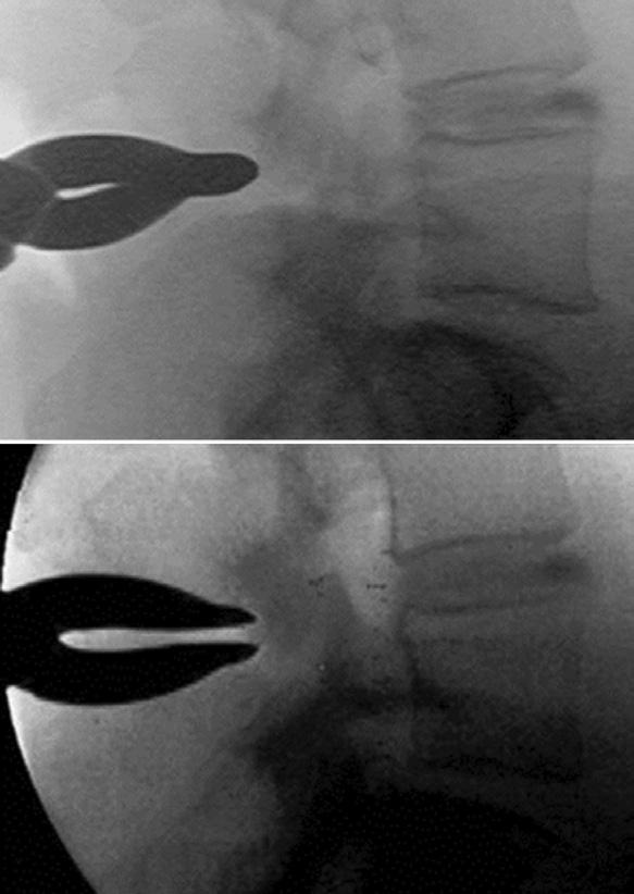
1 Chapter-54 Interspinous Spacers Interspinous Spacers Joshua Abrams, James Zucherman INTRODUCTION Anatomy Lumbar spinal stenosis is a narrowing of the spinal canal leading to a reduction in space available for neural structures and their blood supply. The direct narrowing is due to a constellation of pathologies including thickened lamina, hypertrophied buckled ligamentum flavum, spondylolisthesis, disk bulge and facet arthrosis. In the degenerative cascade as the disk becomes dehydrated, the disk space collapses. Loss of disk height leads to annular bulging and infolding of the ligamentum flavum. As the disk space collapses, the distance between the spinous processes in the posterior column, shortens. 1 Additionally, the posterior facet joints assume a larger load transfer as the disk degenerates leading to facet arthrosis (i.e. osteophyte complex, facet cysts). These degenerative alterations reduce the area of the canal. In the subarticular zone, these changes lead to compression of the traversing nerve root. Compression can also occur within the neuroforamen causing compression of the exiting nerve root. The anteroposterior diameter of the foramen is reduced by the bulging of annulus anteriorly and the hypertrophic facets posteriorly. The foraminal height is reduced by disk dehydration and loss of disk height. This is effectively known as up-down stenosis. The foraminal zone can become further stenotic if the segment has a listhesis, altering the normal concentric keyhole configuration. SURGICAL INDICATIONS Neurogenic intermittent claudication (NIC) is the most common presenting symptom of spinal stenosis. This is a posture-dependent complaint that typically affects patients greater than 50 years of age. Patients present with pain or numbness extending into the buttocks, thighs and/or legs brought on by walking or standing in an erect posture. These postures place the spine in extension and with the aforementioned degenerative changes lead to canal narrowing. Patients frequently receive relief of their symptoms with a forward flexed posture, known as the shopping cart sign. Penning and Wilmink 2 reported on the phenomenon in which a flexed posture increases the spinal canal diameter and effectively reduces the compression on the neural structures (Figs 1A and B). This presentation led to the genesis of the concept of keeping individual spinal segments in


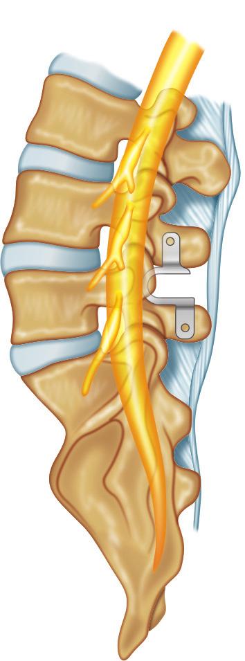
2 460 Section-4 Lumbosacral Spine Techniques A Figs 1A and B: (A) Radiographic illustration depicting focal spinal stenosis with the lumbar spine; (A) In an upright neutral position; (B) In flexion B flexion and limiting the amount of local extension at the site of greatest stenosis. To achieve this, interspinous process devices (IPDs) are placed in between the spinous processes, which act as lever arms of the entire spinal motion segment. Placement of IPDs leads to focal flexion of the spinal segment, keeping the ligamentum flavum tight and effectively increasing the spinal canal diameter. 3 Zucherman et al. demonstrated the placement of an IPD which is superior to non-operative treatment for NIC at 1, 2, and 4 years postoperatively. 4-6 The only interspinous process decompression device approved by the United States Food and Drug Administration for use in the US is the X-STOP (Medtronic, Inc, Minneapolis, MN, USA). Other implants have been used routinely outside the US and some are currently approved for clinical trial. In a magnetic resonance imaging (MRI) cadaver study, Richards et al. reported that the X-STOP increases the neural foraminal area by 26% and the spinal canal area by 18% during extension. In addition, foraminal width is increased by 41% and subarticular diameter by 50% in extension (Figs 2A to D). 7 Other interspinous implants have been developed including: Device for intervertebral assisted motion (DIAM); Medtronic Sofamor Danek, Memphis, TN), Wallis Stabilization System (Zimmer, Bordeaux, France), and COFLEX [Paradigm Spine, New York, NY (Fig. 3)]. Each implant has detailed its own indications, but generally, the goals are rather consistent. 8,9 Placement of X-STOP is indicated in patients, whose symptoms are exacerbated in extension and relieved in flexion, exhibiting NIC. Patients who have failed a trial of conservative management (usually up to 6 months) are the most typical candidates. Spondylolisthesis up to a Meyerding Grade 1 is indicated; unstable segments or segments greater than Meyerding Grade 1 are contraindicated. IPDs may also off-load the facet joint and provide dynamic support and help restore more normal kinematics. IPDs also decrease intradiscal pressure by acting as load sharing devices without altering the spinal biomechanics. 10,11 To date, no prospective clinical outcome of studies have demonstrated proven indications for these implants, with the exception of the X-STOP. 3,4 Understanding of the theoretical advantages and clinical experience guides a surgeon s preference and use. X-STOP and DIAM may also be utilized in patients who are unable to undergo general anesthesia because of medical comorbidities. Additionally, a laminotomy can be performed in conjunction with IPD placement, if the surgeon prefers direct decompression. Placement of Coflex, as discussed later, necessitates either

.")
. Source: Adapted from Richards, et al.")
 DIAM Company Abbott spine Kyphon Inc.")

3 Chapter-54 Interspinous Spacers 461 A C B D Figs 2A to D: (A and B) Axial; (C and D) Pedicular plane magnetic resonance imaging of a specimen in the extended position with and without the implant. The axial slices were taken through the middle of the L3/4 intervertebral disk. A is an intact specimen in the extended position. Notice the narrow subarticular diameter between the anterior facet and posterior annulus (arrows). B is of the same specimen with an X-STOP placed between the L3 and L4 spinous processes. Notice the subarticular diameter in the implanted specimen (arrows). C is of the intact specimen in the extended position, and D is of the same specimen in the extended position with the implant placed at L3/4. The foraminal area and width are noticeably greater in the implanted specimen (arrows). Source: Adapted from Richards, et al. The treatment mechanism of an interspinous process implant for lumbar neurogenic intermittent claudication. Spine 2005 Implant Walls X-STOP/X-STOP PX Coflex (Interspinous U) DIAM Company Abbott spine Kyphon Inc. Paradigm spine Medtronic Launch 2002 (new) (The U) 2001 Developer Senegas J St Francis Inc. Samani J Taylor J FDA Status Approved for clinical trial Approved for clinical use Approved for clinical trial Approved for clinical trial Composition Blocker PEEK Titanium alloy body and PEEK spacer (X-STOP PX ) Technique Implant Removal of supraspinous ligaments necessary Preserves supraspinous ligament Titanium alloy Removal of supraspinous ligaments necessary Silicone core with polyester sleeve Preserves supraspinous ligament FDA indicates Food and Drug Administration; PEEK, PEEK, polyether ether ketone Fig. 3: Relevant features of the interspinous devices Source: Kabir et al. Lumbar Interspinous Spacers
.")
. With the patient placed under light sedation, the operative level is confirmed under fluoroscopy.")
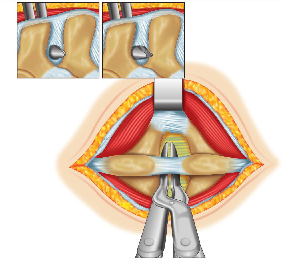
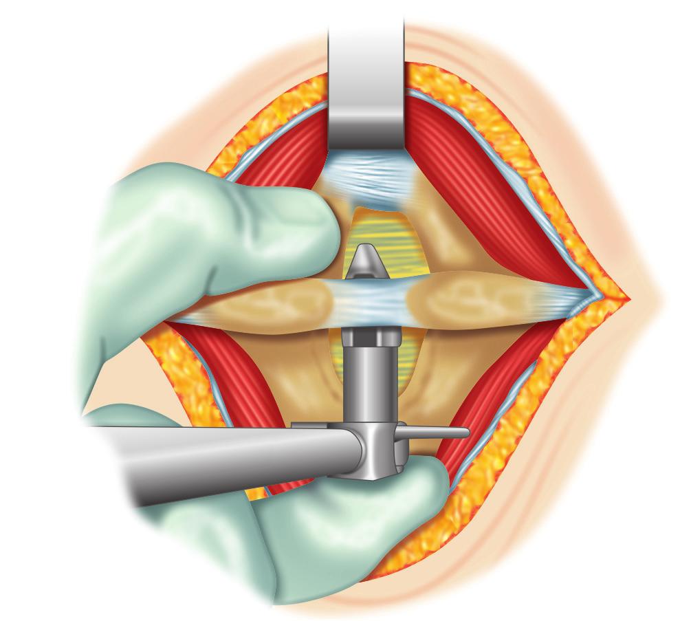
4 462 Section-4 Lumbosacral Spine Techniques a unilateral or bilateral laminotomy. Coflex can also function to augment an interbody fusion (i.e. COFLEX-F). IMPLANTATION OF SPECIFIC SURGICAL TECHNIQUE X-STOP and X-STOP-PK Placement of the X-STOP is performed with the patient in the right lateral decubitus position (Fig. 4A). This procedure can be completed under local anesthetic with light intravenous sedation or under general anesthesia (If a general anesthetic is performed, then the patient is positioned prone with the hips flexed). With the patient placed under light sedation, the operative level is confirmed under fluoroscopy. Local anesthetic is placed in the skin, subcutaneous tissues, fascia and on the posterior rami. To accurately identify the length of incision, needles can be placed at the caudal and cephalad ends of the proposed incision. For placement of a single level implant, a 4 8 cm mid-sagittal incision is completed at the appropriate level. A Cobb elevator is used to sweep the subcutaneous tissues from the dorsal fascia. The posterior lumbodorsal fascia is incised on either side of the spinous processes taking care to preserve the supraspinous ligament. The spinal musculature is then subperiosteally elevated off the spinous processes and transitioning lamina bilaterally. At this point, the participating patient is asked to curl up and flex their spine to maximal capability. The interspinous space is palpated. If the interspinous ligament is overly redundant, a portion of it can be removed with a #12 blade. A small curved dilator is then inserted through the ventral-most margin of the interspinous space from right-to-left (Fig. 4B). Lateral fluoroscopy confirms a ventralmost position within the correct inter spinous space. The small dilator is followed by placement of the larger dilator. Care is taken to maintain a finger opposite of the insertion site during exchange. After the large dilator is removed, the distractor is inserted and utilized to distract the spinous processes (Fig. 4C). Fully flexing the lumbar spine of the participating patient helps with optimal distraction. The distraction can be verified fluoroscopically (Fig. 4D). The distractor has a gauge on it to measure the appropriate size for implant. The X-STOP is then implanted from right-to-left, again with the finger placed on the left side to locate and guide the implant into proper position (Fig. 4E). The implant is inserted until the right wing is flush A B Figs 4A and B
5 Chapter-54 Interspinous Spacers C D E F G H Figs 4C to H 463
 A midline incision is made with the patient in a flexed rightlateral decubitus position; (B) A small dilator is placed through the interspace from right-to-left; (C) After a large dilator is")
 The screw hole is visualized and the universal wing is inserted; (H) The two wings are approximated medially (not shown), and the")
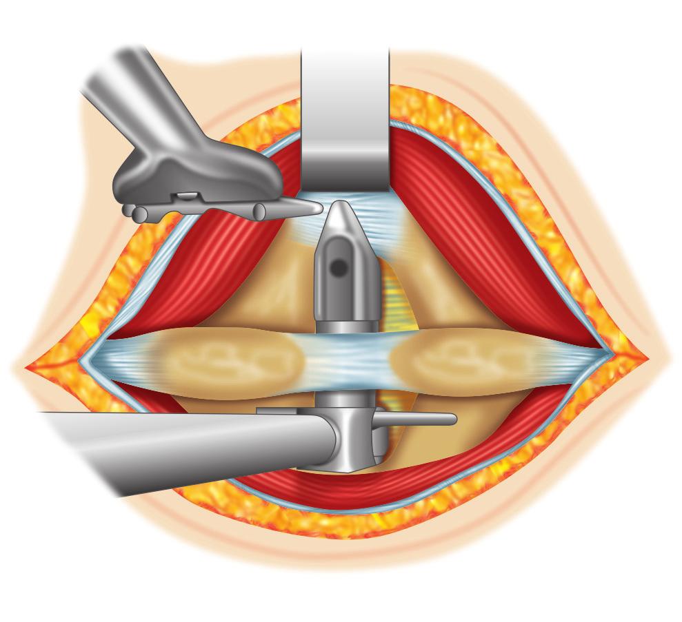
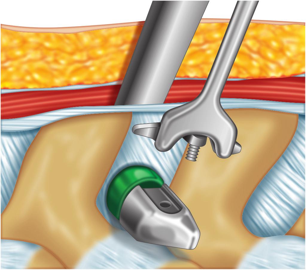
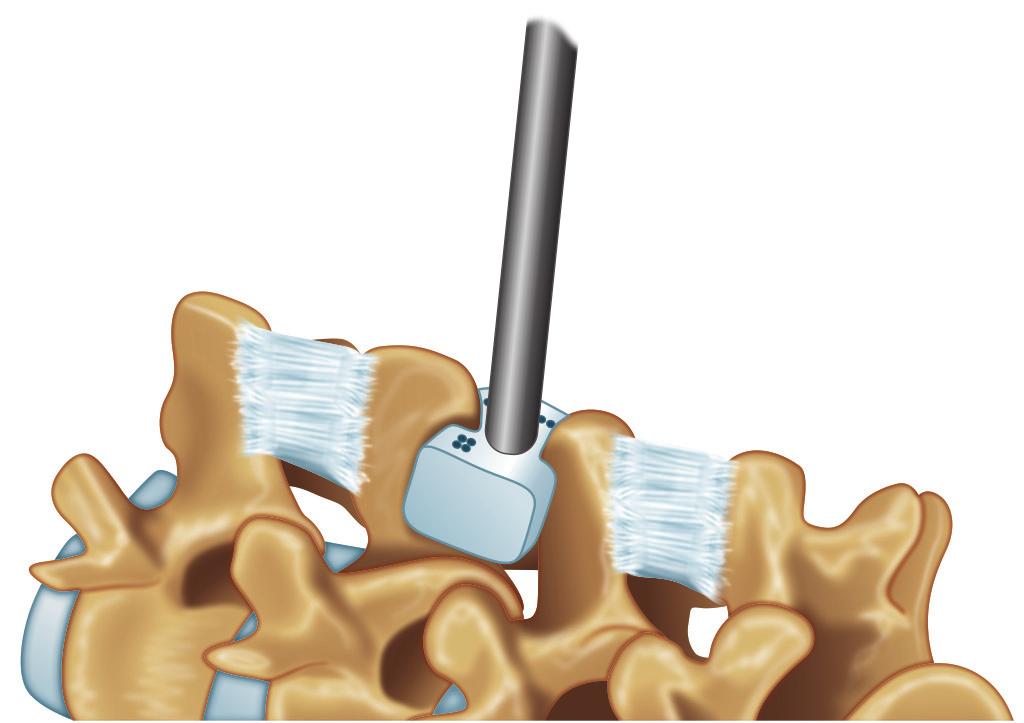
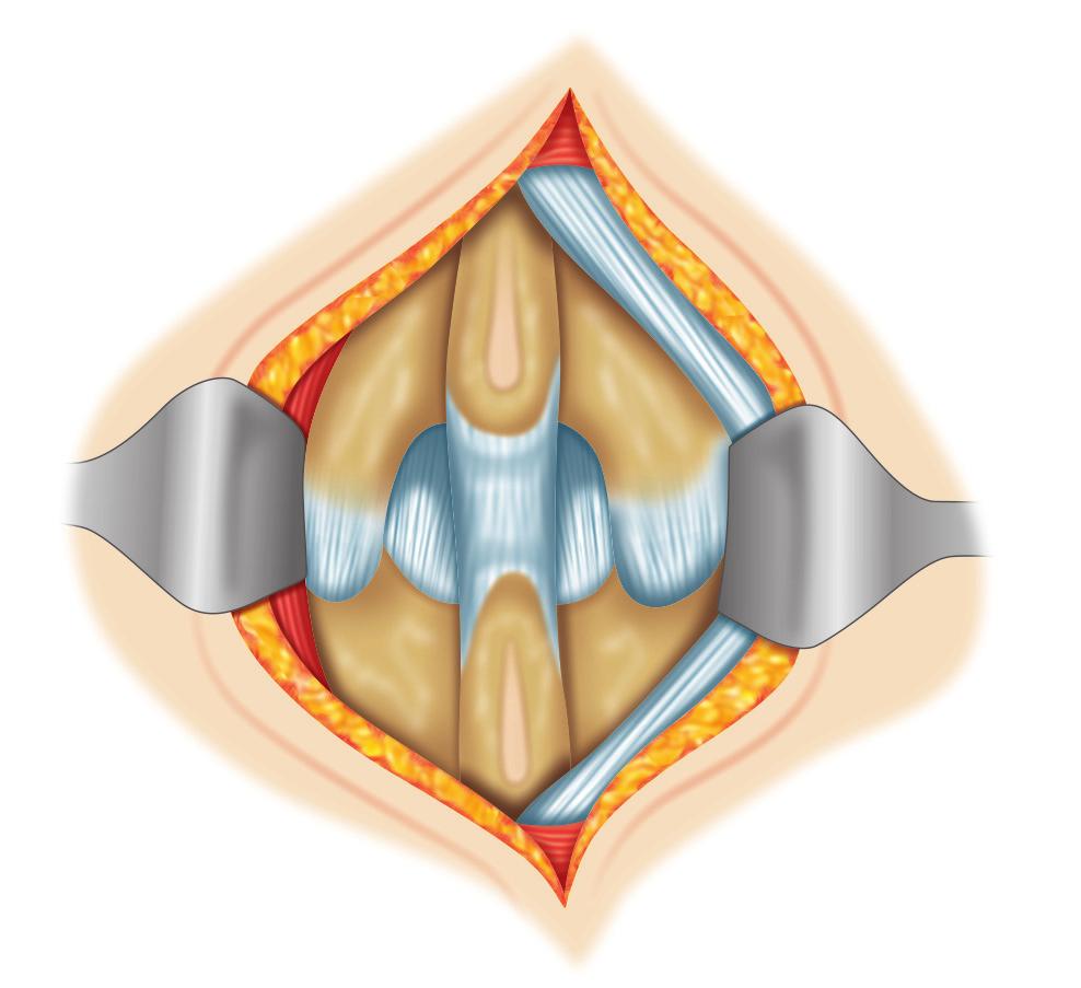
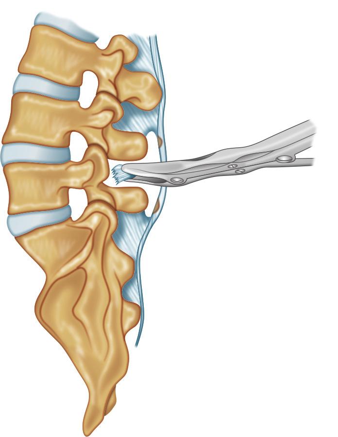
6 464 Section-4 Lumbosacral Spine Techniques I Figs 4A to I: X-STOP Technique. (A) A midline incision is made with the patient in a flexed rightlateral decubitus position; (B) A small dilator is placed through the interspace from right-to-left; (C) After a large dilator is removed, the distractor is placed through the interspinous space; (D) Fluoroscopic confirmation of the sizing distractor; (E) A finger helps guide the insertion of the implant from right-to-left; (F) The right wing should be flush as the universal wing is inserted; (G) The screw hole is visualized and the universal wing is inserted; (H) The two wings are approximated medially (not shown), and the universal wing screw is tighted with a torque-limiting screwdriver; (I) Final radiographic position Source: Adapted from Christie SD, Song JK, Fessler RG. Dynamic Interspinous Process Technology. Spine 2005 against the spinous processes. The universal screw hole on the implant is visualized on the left side. The universal wing on a long driver engages this screw hole and is inserted loosely (Figs 4F and G). The two wings are then approximated medially, and the universal wing screw is tightened with a torque-limiting driver (Fig. 4H). Final fluoroscopy images confirm positioning (Fig. 4I). A drain is typically recommended. A careful layered closure is performed. The two fascia incisions are approximated and sutured to the cuff of midline fascia and supraspinous ligament, separately. The skin is closed in usual fashion. Device for Intervertebral Assisted Mobility (DIAM) Either local or general anesthesia can be performed. Local anesthesia is reserved for single level implants. General anesthesia is utilized for multilevel cases or when implantation is performed in conjunction with a laminotomy. Once anesthetized, the patient is placed in a prone position to reduce the normal lordotic contour of the lumbar spine. Fluoroscopy is used to localize the appropriate interspinous space. A 4 cm midline incision is performed. A Cobb elevator is utilized to sweep the subcutaneous tissues away from midline. Parallel incisions are made on either side of the spinous process through the lumbodorsal fascia, preserving the supraspinous ligament. The paraspinal musculature is then subperiosteally elevated from the spinous processes and lamina both above and below the interspinous space (Fig. 5A). The interspinous ligament is then resected with a rongeur to the level of the ligamentum flavum (Fig. 5B). The interspinous distractor is then placed as ventral as possible in the interspace (Fig. 5C). Distraction is then placed between the two spinous processes to achieve

 Distraction is applied until the appropriate degree of")
 To prepare the implant for insertion, the")


 The tethers are passed around the adjacent")
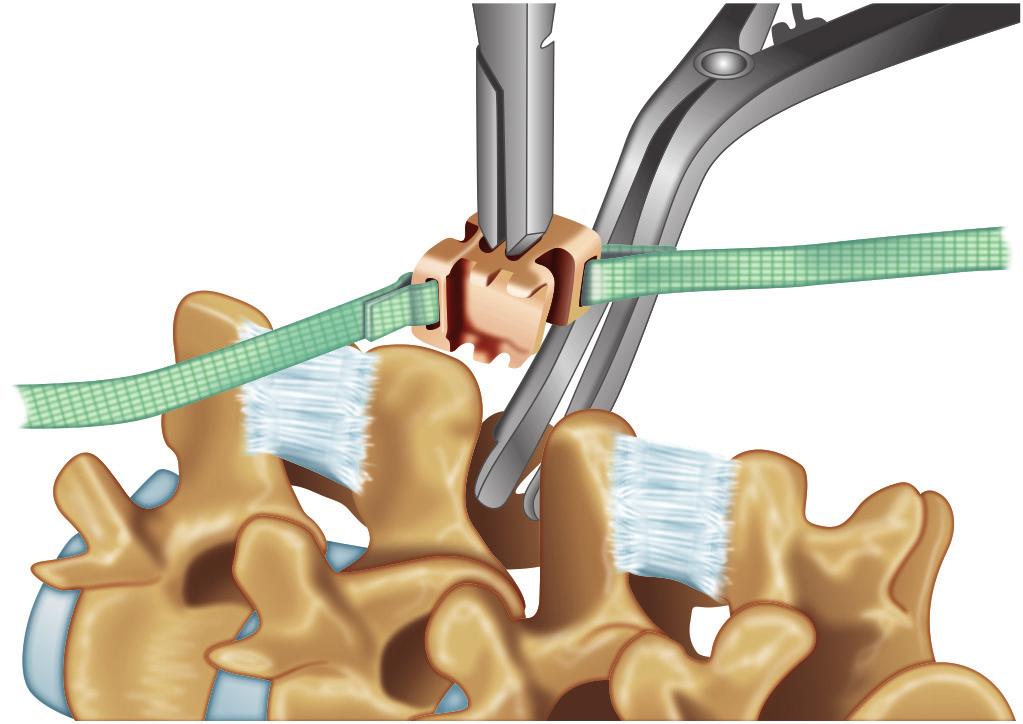
 A crimp tool secures the crimps while applying")
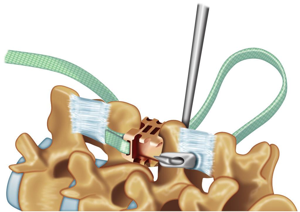
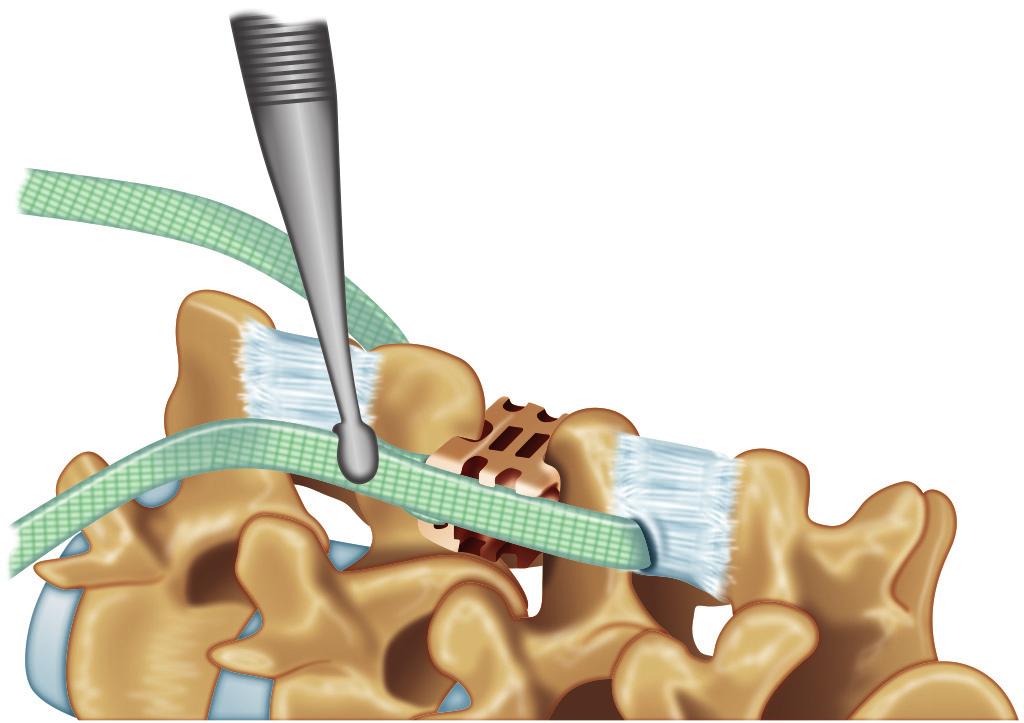
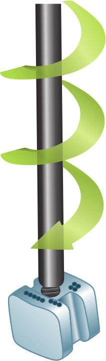
7 Chapter-54 Interspinous Spacers A B C D E F G H I 465 Figs 5A to I: DIAM technique. (A)The interspinous space is prepared by removing the interspinous ligament; (B) Distraction is applied until the appropriate degree of tension is achieved; (C) A series of trials are used to select the proper size implant; (D) To prepare the implant for insertion, the implant is loaded into the inserter. The wings of the implant will fold as the inserter flanges are compressed; (E) Overdistraction may be applied to facilitate insertion of the implant. The DIAM-device is passed through the interspace until the jaws of the inserter are in contact with the corresponding spinous processes. The contralateral tether is also passed through the interspace simultaneously; (F) The tethers are passed around the adjacent spinous processes and then through the loop on the side of the implant; (G) A crimp tool secures the crimps while applying longitudinal tension; (H and I) Final position of the implant. Source: Adapted from Medtronic Sofamor Danic DIAM Spinal Stabilization System Surgical Technique guide
8 466 Section-4 Lumbosacral Spine Techniques the optimal tension of the supraspinous ligament. If a mechanical block to distraction is encountered, interlaminar bony bridges can be resected. Additionally, if the surgeon opts to directly decompress the segment, a laminotomy and/or medial facetectomy can be performed at this point. A series of trials can measure the appropriate size for the DIAM system device (Fig. 5D). The trials provided are 8 mm, 10 mm, 12 mm and 14 mm. To prepare the implant for insertion, the wings of the implant are folded and the implant is compressed (Fig. 5E). With distraction in place, the implant is inserted (Fig. 5F). As the implant is advanced, the wings are deployed to allow the implant to recover its original H shape. The DIAM implant is secured in place with two tethers that are passed around the adjacent spinous processes and fixed into respective loops on the side of the implant (Fig. 5G). Slide the crimps onto the tethers. Apply longitudinal traction to the tethers and compress the crimp tool overlying the crimps to fasten the implant (Figs 5H and I). The excess portion of the tethers is then removed. A drain may be placed, but this is up to the surgeon s preference and experience. The lumbodorsal fascia is approximated and sutured to the midline fascia and supraspinous ligament. The skin is closed in the surgeon s usual fashion. WALLIS After a general anesthesia is administered, the patient is placed in a prone position with pads strategically placed to reproduce a neutral position of physiologic lumbar lordosis to best optimize the effect of the implant. Fluoroscopic localization identifies the segment of interest. At this point a 3 4 cm incision is made. With similar technique as previously stated with the other IPDs, the lumbodorsal fascia is incised on each side of the spinous process. Subperiosteal dissection allows access to the interspinous space. The supraspinous ligament is detached from the two spinous processes and retracted laterally without sectioning. The interspinous space is localized with a finger. The most ventral portion of the interspinous ligament is then resected. The bony junction between the laminae and spinous processes may also be trimmed to help position of the implant as ventral as possible. The interspace is localized and a series of trial spacers are placed with the use of the trial spacer holder (Figs 6A and B). An interlaminar distractor can be placed between the adjacent lamina to provide adequate distraction to achieve optimal distraction and trial spacer placement. The interlaminar distractor should be removed before testing the stability of the trial spacer in the interspinous space. Either the interlaminar distractor or spacer holder can maintain the appropriate distraction for placement of the final implant (Fig. 6C). Implant sizes available in range from 8 mm to 16 mm. Once the PEEK spacer is placed, the two flat woven polyester bands are passed around the corresponding spinous processes. The band passer helps to facilitate the passing of the bands through the adjacent interspinous ligament with minimal disruption (Figs 6D and E). Once passed, the surgeon should verify that the band is flat against the spinous process without being twisted. The fastening clip is aligned in its final position with the arrow pointing towards the center of the spacer. The bands are threaded through a fastening clip (Fig. 6F). The fastening clip is then rotated 360 counter clockwise (Fig. 6G). The clipping forceps is inserted in the opening of the spacer closest to the clip involved. The forceps must be inserted in the spacer opening as deeply as possible to ensure simultaneous introduction of all four stubs on the clip into the corresponding slots on the spacer (Fig. 6H). A torque measuring tightener and tightener guide are mounted onto the implant. A clockwise motion tightens the fastening clips to appropriately tension the bands around the spinous processes (Fig. 6I). Finally, a finishing ring is slipped over the ends of each band and firmly
9 Chapter-54 Interspinous Spacers 467 A B C D E F Figs 6A to F
 The adequate size of the implant is determined by placing different trial spacers; (C) Placement of the final implant can be facilitated by the interlaminar distractor; (D) The band is")
 The clip is rotated 360 counterclockwise and reduced into the spacer with the clipping forceps; (I) The bands are pulled taut and the final tighteners are turned")
10 468 Section-4 Lumbosacral Spine Techniques G H I Figs 6A to J: Wallis Technique. (A and B) The adequate size of the implant is determined by placing different trial spacers; (C) Placement of the final implant can be facilitated by the interlaminar distractor; (D) The band is engaged in the slot at the tip of the band passer; (E) The bands are passed through the adjacent interspinous ligaments; (F) The bands should be flat against the spinous processes; (G) The bands are threaded through the clip; (H) The clip is rotated 360 counterclockwise and reduced into the spacer with the clipping forceps; (I) The bands are pulled taut and the final tighteners are turned clockwise to completion; (J) The excess bands are removed. Source: Adapted from Wallis Posterior Dynamic Stabilization System: Surgical J compressed into final position. The excess bands are removed (Fig. 6J). A drain is frequently placed, but is ultimately dependent on surgeon s preference and experience. A careful layered closure is performed. The supraspinous ligament is then reattached to its original position on the spinous processes through drill holes placed at the dorsal border of the spinous processes. The lumbodorsal fascia is then approximated and sutured closed. The skin is closed in layered fashion. COFLEX, COFLEX-F Under a general anesthesia, the patient is placed in a prone position. Positioning pads are placed to avoid hyperlordosis and achieve either a neutral or semiflexed position in the lumbar spine. Fluoroscopic localization identifies the segment of interest. A 4 cm midline incision is made, centered over the interspace. The paraspinal musculotendinous attachments are elevated from the spinous processes and corresponding lamina. Subperiosteal dissection of the paraspinal muscles allows access to the interspinous space, while preserving the facet capsules (Fig. 7A). An optional unilateral direct microdecompression can be performed at the surgeon s discretion (Fig. 7B). The supraspinous ligament is subperiosteally dissected off of the tips of the spinous processes and retracted laterally with the

11 Chapter-54 Interspinous Spacers A B C G D H E I Figs 7A to I F 469
; (B) Alternatively, if a unilateral decompression is warranted, the supraspinous ligament together with the")
12 470 Section-4 Lumbosacral Spine Techniques J Figs 7A to J: Coflex Technique. (A) After a midline skin incision is performed, the paraspinal musculature is elevated. The supraspinous ligament is preserved, elevated and retracted (to the right as shown); (B) Alternatively, if a unilateral decompression is warranted, the supraspinous ligament together with the fascia and muscle from the opposite side can be mobilized as a whole; (C) The interspinous ligament is resected, in addition to any bony overgrowth of the spinous process; (D) Trials are utilized to define the appropriate size of the implant; (E) The implant is introduced with an inserter; (F to I) Proper depth of insertion is verified fluoroscopically and by passing a beaded tip probe freely between the implant and the dura; (J) If the wings do not have sufficient contact, additional stability can be achieved by crimping the wings. Source: Adapted from Coflex: Surgical Technique. Paradigm Spine contralateral myofascial structures. Care is taken to preserve the supraspinous ligament. If maintenance of the supraspinous ligament is not possible, late reconstruction of the supraspinous ligament is possible in postimplant insertion. The interspinous space is identified, and the interspinous ligament is resected (Fig. 7C). A series of trials are inserted into the interspinous space from dorsal to ventral to define the appropriate implant size (Fig. 7D). Insertion of the trial implants is aided by distraction of the spinous processes. If the spinous processes are hypertrophic or too thick for implant insertion, the wings of the implant can be bent open with specialized wingbending pliers. The final implant is then malleted into position (Figs 7E and F). Proper depth is gauged both fluoroscopically and under direct visualization (Figs 7G and H). The implant should be 3 4 mm from the dura. Passing a ball tip probe in this space can help measure this distance (Fig. 7I). The implant should have a press-fit bony contact to the adjacent spinous processes. Further stability is achieved when the wings of the implant are then compressed against the spinous processes with a crimper (Fig. 7J). Again, if necessary, reconstruction of the supraspinous ligament is completed. If multiple levels are treated, the caudal level is treated first. The wings of the implant are staggered to allow successive implants. The supraspinous ligament is reattached to the spinous processes. This can be achieved by placing drill holes in the dorsal aspect of the corresponding spinous processes. A surgical drain may be placed dependent on surgeon experience and intraoperative bleeding. The lumbodorsal fascia is approximated and sutured. The skin is closed in layered fashion. POSTOPERATIVE CARE Patients are encouraged to ambulate as soon as they feel comfortable. Patients are to avoid heavy lifting and hyperextension activities for 2 6 months, with a gradual return to activities of daily living. Patients should also avoid hyperextension exercises for this period, specifically if a Coflex has implanted. After any procedure, the patient is encouraged to maintain constant spine health. COMPLICATIONS Complications related to implantation of IPDs are few. There are complications associated with undergoing any surgical procedure and complications

13 Chapter-54 Interspinous Spacers 471 were 6% over 2 years in the study of Zucherman et al. 4 and Siddiqui et al. reported less than 10%. 13 The surgical technique of most of these implants does not require significant alteration in the anatomy, and therefore, does not prevent a secondary, conventional approach. KEY POINTS Fig. 8: Occult spinous process fracture visualized with sagittal CT imaging. (Adapted from Kim et al. Occult spinous process fractures associated with interspinous process Spacers) that are specific to each implant. Due to the nature of distraction imparted either during the implanting process or the distraction placed when an extension load is upon the implant, spinous process fracture is an uncommon, but potential complication (Fig. 8). 12 It is possible to fracture the spinous process if too much force is applied to the sizing distractor or when passing an implant. If a fracture compromising the load bearing capacity is encountered intraoperatively, the procedure is simply converted to a laminectomy with or without fusion since the design of the interspinous spacers relies on the integrity of the intact cephalad and caudal spinous processes. The author routinely checks the bone density of hips in all patients preoperatively. In the author s 600 patient experiences with X-STOP, T-scores less than -2.8 are more prone to failure by settling or fracture. In the US. clinical study for X-STOP, there was one case of traumatic dislodgement.5 This remains an uncommon possibility for each of the implants discussed. Additional rare complications include infections, seroma and wound dehiscence. The most likely unfavorable outcome is failure to relieve the symptoms associated with lumbar spinal stenosis. Revision rates after X-STOP implantation The initial insertion point is generally at the level of the medial left lamina of the cephalad level being instrumented. Use a finger to identify the insertion site of the interspinous space during exchange of instruments. Ventral placement of the implant is usually desired (unless the interspinous space has a V configuration); this may require partial resection of hypertrophic medial facet processes and osteophytes. Preoperative DEXA scan may help guide a surgeon in the amount of distraction placed and the size of the implant inserted. The interspinous spacer does not increase slippage in a low grade spondylolisthesis. Implantation of an interspinous spacer usually leads to significant pain relief (VAS) and functional restoration (ODI or ZCQ) in properly indicated patients. Two years and four years outcome of studies for X STOP have demonstrated an 85% and 78% success rate, respectively. 5,6 X-STOP implant has proven to improve the radiographic parameters of foraminal height, width, and cross-sectional area more than the DIAM and Wallis implants; however, there is no data to determine a statistically significant difference in symptom relief among the three implants. The X-STOP is only recommended and proven for neurogenic intermi ttant claudication patients. Proof of efficacy and indications for the other implants mentioned is pending.
14 472 Section-4 Lumbosacral Spine Techniques REFERENCES 1. Infusa A, An HS, Lim TH, et al. Anatomic changes of the spinal canal and intervertebral foramen associated with flexion-extension movement. Spine. 1996;21: Penning L, Wilmink JT. Posture-dependent bilateral compression of L4 or L5 nerve roots in facet hypertrophy. A dynamic CT-myelographic study. Spine. 1987; 12: Zucherman J, Simons P, Timothy J. X STOP interspinous implant for lumbar spinal decompression. Brussels International Spine Symposium. 2005; Zucherman JF, Hsu KY, Hartjen CA, et al. A prospective randomized multi-center study for the treatment of lumbar spinal stenosis with the X-STOP interspinous implant: 1-year results. Eur Spine J. 2004;13(1): Zucherman JF, Hsu KY, Hartjen CA, et al. A multicenter, prospective, randomized trial evaluating the X-STOP interspinous process decompression system for the treatment of neurogenic intermittent claudication: two-year follow-up results. Spine. 2005;30: Kondrashov DG, Hannibal M, Hsu KY, et al. Interspinous process decompression with the X-STOP device for lumbar spinal stenosis: a 4-year follow-up study. J Spinal Disord Tech. 2006;19: Richards JC, Majumdar S, Lindsey DP, et al. The treatment mechanism of an interspinous process implant for lumbar neurogenic intermittent claudication. Spine. 2005;30(7): Kabir SM, Gupta SR, Casey AT. Lumbar interspinous spacers: a systematic review of clinical and biomechanical evidence. Spine. 2010;35(25):E Christie SD, Song JK, Fessler RG. Dynamic Interspinous Process Technology. Spine. 2005;30:S Lindsey DP, Swanson KE, Fuchs P, et al. The effects of an interspinous implant on the kinematics of the instrumented and adjacent levels in the lumbar spine. Spine. 2003;28: Nandakumar A, Clark NA, Peehal JP, et al. The increase in dural sac area is maintained at 2 years after X-STOP implantation for the treatment of spinal stenosis with no significant alteration in lumbar spine range of movement. The Spine Journal. 2010;10: Kim DH, Tantorski M, Shaw J, et al. Occult spinous process fractures associated with interspinous process spacers. Spine Epub; Siddiqui M, Karadimas E, Nicol M, et al. Effects of X-STOP device on sagittal lumbar spine kinematics in spinal stenosis. J Spinal Disord Tech. 2006;19: Surgical Technique Guides: DIAM Spinal Stabilization System: Surgical Technique. May 2008 (Version H) P Medtronic Sofamor Danek. Coflex TM: Surgical Technique. Paradigm Spine. Coflex_surgical_technique.pdf Wallis Posterior Dynamic Stabilization System: Surgical Technique. Zimmer (Abbott Spine). [online] Available from [Accessed December, 2011].
PARADIGM SPINE. Minimally Invasive Lumbar Fusion. Interlaminar Stabilization
 PARADIGM SPINE Minimally Invasive Lumbar Fusion Interlaminar Stabilization 2 A UNIQUE MIS ALTERNATIVE TO PEDICLE SCREW FIXATION The Gold Standard The combined use of surgical decompression and different
UniWallis TM Posterior Dynamic Stabilization System
 UniWallis TM Posterior Dynamic Stabilization System Surgical Technique Solutions by the people of Zimmer Spine. zimmerspine.eu Table of Contents Indications/Contraindications 2 UniWallis Instruments 3
PARADIGM SPINE. Brochure. coflex-f Minimally Invasive Lumbar Fusion
 PARADIGM SPINE Brochure coflex-f Minimally Invasive Lumbar Fusion coflex-f THE UNIQUE, MINIMALLY INVASIVE FUSION DEVICE The coflex-f implant is designed to deliver surgeon confidence and patient satisfaction.
Technique Guide. StenoFix. Interspinous distraction after surgical decompression.
 Technique Guide StenoFix. Interspinous distraction after surgical decompression. Table of Contents Introduction StenoFix 2 Indications and Contraindications 4 Surgical Technique Preoperative Planning
High failure rate of the interspinous distraction device (X-Stop) for the treatment of lumbar spinal stenosis caused by degenerative spondylolisthesis
 for the treatment of lumbar spinal stenosis caused by degenerative spondylolisthesis") Eur Spine J (2008) 17:188 192 DOI 10.1007/s00586-007-0492-x ORIGINAL ARTICLE High failure rate of the interspinous distraction device (X-Stop) for the treatment of lumbar spinal stenosis caused by degenerative
Eur Spine J (2008) 17:188 192 DOI 10.1007/s00586-007-0492-x ORIGINAL ARTICLE High failure rate of the interspinous distraction device (X-Stop) for the treatment of lumbar spinal stenosis caused by degenerative
LUMBAR SPINAL STENOSIS
 LUMBAR SPINAL STENOSIS Always occurs in the mobile segment. Factors play role in Stenosis Pre existing congenital or developmental narrowing of the lumbar spinal canal Translation of one anatomic segment
InSWing. Unilateral, Minimal Invasive Interspinous Spacer INTERNATIONAL EDITION
 InSWing I N T E R S P I N O U S S P A C E R Unilateral, Minimal Invasive Interspinous Spacer INTERNATIONAL EDITION Table of Contents 1 INTRODUCTION 2 PATIENT POSITIONING 3 OPERATIVE 10 IMPLANT REMOVAL
Technique Guide. ARCH Laminoplasty System. Dedicated System for Open-door Laminoplasty.
 Technique Guide ARCH Laminoplasty System. Dedicated System for Open-door Laminoplasty. Table of Contents Introduction Overview 2 AO ASIF Principles 4 Indications and Contraindications 5 Product Information
SURGICAL TECHNIQUE MANUAL. InterFuse T
 1 CONTENTS InterFuse T Product Description 3 Indications for Use 3 X-Ray Marker Locations 4 Product Specifications 4 Instrument Set 5 Step 1 Preoperative Planning 8 Patient Positioning 8 Step 2 Disc Removal
Current Spine Procedures
 SPINE BOOT CAMP: WHAT YOU DON T KNOW MAY COST YOU! David Abraham, M.D. The Reading Neck and Spine Center Reading, PA Current Spine Procedures Epidural/Transforaminal Injections Lumbar Procedures Laminectomy
Am I eligible for the TOPS study? Possibly, if you suffer from one or more of the following conditions:
 Am I eligible for the TOPS study? Possibly, if you suffer from one or more of the following conditions: Radiating leg pain Greater leg / buttock pain than back pain Severe pain sets in when walking as
VTI INTERFUSE T SURGICAL TECHNIQUE FORWARD THINKING FOR THE BACK. 1/20
 VTI INTERFUSE T SURGICAL TECHNIQUE FORWARD THINKING FOR THE BACK. 1/20 CONTENTS InterFuse T Product Description Indications for Use X-Ray Marker Locations Product Specifications Instrument Set 3 4 5 STEP
ARCH Laminoplasty System. Dedicated System for Open-door Laminoplasty.
 ARCH Laminoplasty System. Dedicated System for Open-door Laminoplasty. Surgical Technique This publication is not intended for distribution in the USA. Instruments and implants approved by the AO Foundation.
Corporate Medical Policy
 Corporate Medical Policy Interspinous and Interlaminar Stabilization/Distraction Devices File Name: Origination: Last CAP Review: Next CAP Review: Last Review: interspinous_and_interlaminar_stabilization-distraction_devices
Module: #15 Lumbar Spine Fusion. Author(s): Jenni Buckley, PhD. Date Created: March 27 th, Last Updated:
: Jenni Buckley, PhD. Date Created: March 27 th, Last Updated:") Module: #15 Lumbar Spine Fusion Author(s): Jenni Buckley, PhD Date Created: March 27 th, 2011 Last Updated: Summary: Students will perform a single level lumbar spine fusion to treat lumbar spinal stenosis.
Module: #15 Lumbar Spine Fusion Author(s): Jenni Buckley, PhD Date Created: March 27 th, 2011 Last Updated: Summary: Students will perform a single level lumbar spine fusion to treat lumbar spinal stenosis.
Lumbar spinal stenosis is narrowing of the spinal canal that results in compression of the cauda
 1 CHAPTER 32: CLINICAL RESULTS OF THE IDE TRIAL OF X-STOP INTERSPINOUS SYSTEMS ELIZABETH YU AND JAMES ZUCHERMAN Lumbar spinal stenosis Lumbar spinal stenosis is narrowing of the spinal canal that results
5/19/2017. Interspinous Process Fixation with the Minuteman G3. What is the Minuteman G3. How Does it Work?
 Interspinous Process Fixation with the Minuteman G3 LLOYDINE J. JACOBS, MD CASTELLVI SPINE MEETING MAY 13, 2017 What is the Minuteman G3 The world s first spinous process plating system that is: Minimally
L8 Spine System SURGICAL TECHNIQUE. Add: No.1-8, Tianshan Road, Xinbei District, Changzhou, Jiangsu, China
 Add: No.-8, Tianshan Road, Xinbei District, Changzhou, Jiangsu, China 23022 Tel: 0086 59 8595556 Fax: 0086 59 859555 Http://www.kanghui.com Add: F25, Shanghai International Pharmaceutical Trad & Exhibition
Corporate Medical Policy
 Corporate Medical Policy Image-Guided Minimally Invasive Decompression (IG-MLD) for File Name: Origination: Last CAP Review: Next CAP Review: Last Review: image-guided_minimally_invasive_decompression_for_spinal_stenosis
VTI INTERFUSE S SURGICAL TECHNIQUE FORWARD THINKING FOR THE BACK.
 VTI INTERFUSE S SURGICAL TECHNIQUE FORWARD THINKING FOR THE BACK. CONTENTS InterFuse S Product Description Indications for Use X-Ray Marker Locations and Product Specifications Instrument Set 3 4 5-7 STEP
In-Space. Interspinous distraction through a mini-open, posterior, unilateral approach.
 In-Space. Interspinous distraction through a mini-open, posterior, unilateral approach. Surgical Technique Posterior Approach PRODUCT OBSOLETED 30th September 2017 DSEM/SPN/0915/0348(1) This publication
PARADIGM SPINE. Patient Information. Treatment of a Narrow Lumbar Spinal Canal
 PARADIGM SPINE Patient Information Treatment of a Narrow Lumbar Spinal Canal Dear Patient, This brochure is intended to inform you of a possible treatment option for narrowing of the spinal canal, often
Chapter 35. Clinical Results of IDE Trial of X- Stop Interspinous Systems Lumbar Spinal Stenosis Treatment 2
 Chapter 35 Clinical Results of IDE Trial of X- Stop Interspinous Systems 35.1 Lumbar Spinal Stenosis 2 35.2 Treatment 2 35.3 Operative Intervention 2 35.4 Biomechanics/Design Rationale 3 35.5 Biomechanical
Protocol. Interspinous and Interlaminar Stabilization/Distraction Devices (Spacers)
") Interspinous and Interlaminar Stabilization/Distraction Devices (701107) Medical Benefit Effective Date: 10/01/13 Next Review Date: 07/15 Preauthorization No Review Dates: 07/07, 07/08, 09/09, 09/10, 07/11,
Interspinous and Interlaminar Stabilization/Distraction Devices (701107) Medical Benefit Effective Date: 10/01/13 Next Review Date: 07/15 Preauthorization No Review Dates: 07/07, 07/08, 09/09, 09/10, 07/11,
Surgical Technique Manual
 InterFuse S Interbody Fusion System Surgical Technique Manual VERTEBRAL TECHNOLOGIES MS 4043-02 Rev. O Product Overview Introduction The VTI InterFuse S implant is an interbody fusion device that combines
Royal Oak IBFD System Surgical Technique Posterior Lumbar Interbody Fusion (PLIF)
") Royal Oak IBFD System Surgical Technique Posterior Lumbar Interbody Fusion (PLIF) Preoperative Planning Preoperative planning is necessary for the correct selection of lumbar interbody fusion devices.
Royal Oak IBFD System Surgical Technique Posterior Lumbar Interbody Fusion (PLIF) Preoperative Planning Preoperative planning is necessary for the correct selection of lumbar interbody fusion devices.
It consist of two components: the outer, laminar fibrous container (or annulus), and the inner, semifluid mass (the nucleus pulposus).
, and the inner, semifluid mass (the nucleus pulposus).") Lumbar Spine The lumbar vertebrae are the last five vertebrae of the vertebral column. They are particularly large and heavy when compared with the vertebrae of the cervical or thoracicc spine. Their bodies
Lumbar Spine The lumbar vertebrae are the last five vertebrae of the vertebral column. They are particularly large and heavy when compared with the vertebrae of the cervical or thoracicc spine. Their bodies
ARCH Laminoplasty System
 Dedicated System for Open-door Laminoplasty ARCH Laminoplasty System Surgical Technique Image intensifier control This description alone does not provide sufficient background for direct use of DePuy Synthes
NewBridge. Laminoplasty Fixation INTERNATIONAL EDITION
 NewBridge L A M I N O P L A S T Y F I X A T I O N S Y S T E M Laminoplasty Fixation INTERNATIONAL EDITION Table of Contents 1 INTRODUCTION 2 PRE-OPERATIVE 3 OPERATIVE 10 INSTRUCTIONS FOR USE 12 PART NUMBERS
L-VARLOCK. Posterior Lumbar Cage with adjustable lordosis. S urgical T echnique
 L-VARLOCK Posterior Lumbar Cage with adjustable lordosis S urgical T echnique Introduction Designed and manufactured by KISCO International, L-VARLOCK cages are made of titanium alloy Ti 6AI 4V (standards
mild Devices Kit - Instructions for Use
 INDICATION FOR USE The Vertos mild Devices are specialized surgical instruments intended to be used to perform lumbar decompressive procedures for the treatment of various spinal conditions. CONTENTS AND
PARADIGM SPINE. Interlaminar Technology. Interlaminar Implant
 PARADIGM SPINE Interlaminar Technology Interlaminar Implant SPINAL STENOSIS WITH BACK PAIN THE RATIONALE FOR STABILIZATION For the treatment of spinal stenosis, surgeons have various treatment options.
8/4/2012. Causes and Cures. Nucleus pulposus. Annulus fibrosis. Vertebral end plate % water. Deforms under pressure
 Causes and Cures Intervertebral discs Facet (zygopophyseal) joints Inter body joints Spinal nerve roots Nerve compression Pathological conditions Video Causes of back pain Nucleus pulposus Annulus fibrosis
In-Space. Percutaneous interspinous distraction.
 In-Space. Percutaneous interspinous distraction. Surgical Technique PRODUCT OBSOLETED 30th September 207 DSEM/SPN/095/0344() This publication is not intended for distribution in the USA. Instruments and
VERTEX SELECT. surgical technique. adjustability. Flexibility. adaptability. Reconstruction System
 VERTEX SELECT Reconstruction System surgical technique adjustability. Flexibility. adaptability. adjustability. Flexibility. adaptability. The VERTEX SELECT Reconstruction System is a comprehensive set
BAK/C Cervical Anterior Interbody Fusion System
 Surgical Technique BAK/C Cervical Anterior Interbody Fusion System The Comfortable Choice for Cervical Fusion BAK/C Cervical Surgical Technique 1 The BAK/C Cervical Fusion System is an alternative to conventional
Fusion Device. Surgical Technique. Cervical Interbody Fusion with Trabecular Metal Technology
 TM-S Fusion Device Surgical Technique Cervical Interbody Fusion with Trabecular Metal Technology 2 TM-S Fusion Device Surgical Technique Disclaimer This surgical technique is not intended for use in the
Synex System TECHNIQUE GUIDE. An expandable vertebral body replacement device
 Synex System TECHNIQUE GUIDE An expandable vertebral body replacement device Original Instruments and Implants of the Association for the Study of Internal Fixation AO ASIF Synex System Overview The Synex
Solitaire Anterior Spinal System
 Surgical Technique Solitaire Anterior Spinal System Independent Stabilization for the Anterior Column Available in Titanium and Contents Introduction... Page 1 Design Features... Page 2 Instruments...
Hinged Laminoplasty System surgical technique
 BlackbirdTM Hls Hinged Laminoplasty System surgical technique Blackbird TM Hls The ChoiceSpine Blackbird Hinged Laminoplasty System (HLS) design eliminates fitting plates through trial and error bending.
Surgical Technique. TraXis. Precision. Transforaminal Lumbar Interbody Fusion Spacer. The Art & Science of Spine Surgery
 Surgical Technique Precision TraXis Transforaminal Lumbar Interbody Fusion Spacer The Art & Science of Spine Surgery Table of Contents Introduction 3 Indications 4 Key Instruments 5 Surgical Technique
Imola Lateral IBF System Surgical Technique
 Imola Lateral IBF System Surgical Technique IMOLA CIRCUIT TABLE OF CONTENTS Design Rationale Instructions for Use Surgical Technique 1. Table Mounting 2. Surgical Planning & Targeting 3. Access and Preparation
X-spine Surgical Technique
 X-spine Surgical Technique The X90 Pedicle Screw System Revolutionary Design and Function This document is intended exclusively for experts in the field, particularly physicians, and is not intended for
INTERVERTEBRAL BODY FUSION DEVICE. Surgical Technique
 INTERVERTEBRAL BODY FUSION DEVICE Surgical Technique Joint Spine Sports Med MectaLIF Oblique & Posterior Surgical Technique 2 INDEX 1. INTRODUCTION 4 1.1 Materials & Markers 5 2. INDICATIONS 6 3. CONTRAINDICATIONS
M.I.S. MAKE IT SMART IN ONE SYSTEM. Surgical Technique. Hip Knee Spine Navigation
 M.I.S. MAKE IT SMART IN ONE SYSTEM Surgical Technique Hip Knee Spine Navigation M.U.S.T. Mini Open Surgical Technique Hip Knee Spine Navigation 2 C O N T E N T S 1 INTRODUCTION 4 2 SURGICAL TECHNIQUE 5
Interspinous and Interlaminar Stabilization/Distraction Devices (Spacers)
") Federal Employee Program 1310 G Street, N.W. Washington, D.C. 20005 202.942.1000 Fax 202.942.1125 7.01.107 Page: 1 of 12 Last Review Status/Date: June 2015 Interspinous and Interlaminar Stabilization/Distraction
Federal Employee Program 1310 G Street, N.W. Washington, D.C. 20005 202.942.1000 Fax 202.942.1125 7.01.107 Page: 1 of 12 Last Review Status/Date: June 2015 Interspinous and Interlaminar Stabilization/Distraction
Alamo T Transforaminal Lumbar Interbody System Surgical Technique
 Transforaminal Lumbar Interbody System Surgical Technique Table of Contents Indications and Device Description.............. 1 Alamo T Implant Features and Instruments...........2 Surgical Technique......................
POSTERIOR CERVICAL FUSION
 AN INTRODUCTION TO PCF POSTERIOR CERVICAL FUSION This booklet provides general information on the Posterior Cervical Fusion (PCF) surgical procedure for you to discuss with your physician. It is not meant
UniLink Interspinous Fusion System UniLink 5/1 Interspinous Fusion System UniLink Graft. Surgical Technique
 UniLink Interspinous Fusion System UniLink 5/1 Interspinous Fusion System UniLink Graft Surgical Technique 2 UniLink and UniLink 5/1 Interspinous Fusion System Surgical Technique UniLink and Unlink 5/1
Handling instructions. USS Low Profile. Thoracolumbar posterior fixation system.
 Handling instructions USS Low Profile. Thoracolumbar posterior fixation system. U Table of contents Introduction Indications and contraindications 3 USS Low Profile implants 4 Handling implants with stick
Get back to: my life. Non-fusion treatment for lumbar spinal stenosis
 Get back to: my life Non-fusion treatment for lumbar spinal stenosis Do you have any of these symptoms? numbness, weakness or pain in the lower legs When any of these conditions occur, the spinal nerve,
3D titanium interbody fusion cages sharx. White Paper
 3D titanium interbody fusion cages sharx (SLM selective laser melted) Goal of the study: Does the sharx intervertebral cage due to innovative material, new design, and lordotic shape solve some problems
Aperius interspinous implant versus open surgical decompression in lumbar spinal stenosis
 The Spine Journal 11 (2011) 933 939 Clinical Study interspinous implant versus open surgical decompression in lumbar spinal stenosis Roberto Postacchini, MD a, Emiliano Ferrari, MD b, Gianluca Cinotti,
Contact Fusion Cage. Surgical Technique
 Contact Fusion Cage Surgical Technique Image intensifier control This description alone does not provide sufficient background for direct use of DePuy Synthes products. Instruction by a surgeon experienced
Lumbar Spinal Stenosis
 Lumbar Spinal Stenosis This article is also available in Spanish: Estenosis de la columna lumbar (topic.cfm?topic=a00701). A common cause of low back and leg pain is lumbar spinal stenosis. As we age,
T.L.I.F. Surgical Technique. Featuring the T.L.I.F. SG Instruments, VG2 PLIF Allograft, and the MONARCH Spine System.
 Surgical Technique T.L.I.F. Transforaminal Lumbar Interbody Fusion Featuring the T.L.I.F. SG Instruments, VG2 PLIF Allograft, and the MONARCH Spine System. CONSULTING SURGEON Todd Albert, M.D. Rothman
Interbody fusion cage for the transforaminal approach. Travios. Surgical Technique
 Interbody fusion cage for the transforaminal approach Travios Surgical Technique Image intensifier control This description alone does not provide sufficient background for direct use of DePuy Synthes
Surgical Technique INTERSOMATIC CERVICAL CAGE
 R INTERSOMATIC CERVICAL CAGE NEOCIF IMPLANTS NEOCIF is an implant designed to make anterior cervical interbody fusion (ACIF) easier and to remove the need for structural autologous graft. The cage is made
Patient Information MIS LLIF. Lateral Lumbar Interbody Fusion Using Minimally Invasive Surgical Techniques
 Patient Information MIS LLIF Lateral Lumbar Interbody Fusion Using Minimally Invasive Surgical Techniques Table of Contents Anatomy of Spine...2 General Conditions of the Spine....4 What is Spondylolisthesis....5
Interspinous and Interlaminar Stabilization / Distraction Devices (Spacers)
") Interspinous and Interlaminar Stabilization / Distraction Devices (Spacers) Policy Number: 7.01.107 Last Review: 9/2014 Origination: 2/2007 Next Review: 9/2015 Policy Blue Cross and Blue Shield of Kansas
Interspinous and Interlaminar Stabilization / Distraction Devices (Spacers) Policy Number: 7.01.107 Last Review: 9/2014 Origination: 2/2007 Next Review: 9/2015 Policy Blue Cross and Blue Shield of Kansas
C-THRU Anterior Spinal System
 C-THRU Anterior Spinal System Surgical Technique Manufactured From Contents Introduction... Page 1 Design Features... Page 2 Instruments... Page 3 Surgical Technique... Page 4 Product Information... Page
PARADIGM SPINE. Anterior Cervical Fusion Cage. Cervical Interbody Fusion
 PARADIGM SPINE Anterior Cervical Fusion Cage Cervical Interbody Fusion DESIGN RATIONALE The OptiStrain TM C* interbody fusion cage follows well established biomechanical principles: The slot design of
PROF. EPIMENIO RAMUNDO ORLANDO
 PROF. EPIMENIO RAMUNDO ORLANDO Lumbar Spinal Stenosis - Definition N.I.C. caused by lumbar stenosis was firstly described by Verbiest (1954)*1 and is characterized by contemporary single or multiple factors:
PILLAR AL. Anterior Lumbar Interbody Fusion (ALIF) and Partial Vertebral Body Replacement (pvbr) PEEK Spacer System OPERATIVE TECHNIQUE
 and Partial Vertebral Body Replacement (pvbr) PEEK Spacer System OPERATIVE TECHNIQUE") PILLAR AL PEEK Spacer System Anterior Lumbar Interbody Fusion (ALIF) and Partial Vertebral Body Replacement (pvbr) OPERATIVE TECHNIQUE Table of Contents 1 INTRODUCTION 2 PRE-OPERATIVE TECHNIQUE 3 OPERATIVE
PILLAR AL PEEK Spacer System Anterior Lumbar Interbody Fusion (ALIF) and Partial Vertebral Body Replacement (pvbr) OPERATIVE TECHNIQUE Table of Contents 1 INTRODUCTION 2 PRE-OPERATIVE TECHNIQUE 3 OPERATIVE
Dorsal Cervical Surgeries and Techniques
 Dorsal Cervical Approaches Dorsal Cervical Surgeries and Techniques Gregory R. Trost, MD Professor and Vice Chair of Neurological Surgery University of Wisconsin-Madison Advantages Straightforward Easily
EFSPINE CERVICAL COMBINED SET DISC PROTHESIS ORGANIZER BOX
 EFSPINE CERVICAL COMBINED SET INSTRUMENTS CERVICAL CAGE & DISC PROTHESIS ORGANIZER BOX Cervical Thoracic Thoraco - Lumbar Sacral EFSPINE CERVICAL COMBINED SET CERVICAL IMPLANTS INTRODUCTION Cervical Disc
Patient Information MIS LLIF. Lateral Lumbar Interbody Fusion Using Minimally Invasive Surgical Techniques
 Patient Information MIS LLIF Lateral Lumbar Interbody Fusion Using Minimally Invasive Surgical Techniques Table of Contents Anatomy of Spine....2 General Conditions of the Spine....4 What is Spondylolisthesis....5
LUMBAR POSTERIOR MINIMALLY INVASIVE SYSTEM. Surgical Technique
 LUMBAR POSTERIOR MINIMALLY INVASIVE SYSTEM Surgical Technique Joint Spine Sports Med M.U.S.T. Mini Open Surgical Technique Joint Spine Sports Med CAUTION Federal law (USA) restricts this device to sale
Coflex TM for Lumbar Stenosis with
 Coflex TM for Lumbar Stenosis with Segmental Instability : 1 yr outcomes Eun-Sang Kim, M.D., Ph.D. Clinical Professor Dept of Neurosurgery Samsung Medical Center Seoul, Korea Surgery for Spinal Stenosis
Advantage ALIF. Keith Shevlin Managing Director
 Advantage ALIF Unit 10, 9-11 Myrtle Street, Crows Nest NSW 2065 Keith Shevlin Managing Director keithshevlin@precisionsurgical.com.au Advantage ALIF Introduction & Indications for Use 1 Surgical Technique
Posterior Lumbar Interbody Fusion System
 Px Posterior Lumbar Interbody Fusion System Px PEEK INTERBODY FUSION SYSTEM INDICATIONS FOR USE The Innovasis Px PEEK IBF System is an intervertebral body fusion device for use in patients with degenerative
Populations Interventions Comparators Outcomes Individuals: With spinal stenosis and up to grade I spondylolisthesis
 Interspinous and Interlaminar Stabilization/Distraction Devices (701107) Medical Benefit Effective Date: 10/01/17 Next Review Date: 07/19 Preauthorization No Review Dates: 07/07, 07/08, 09/09, 09/10, 07/11,
Populations Interventions Comparators Outcomes Individuals: With lumbar spinal stenosis
 Image-Guided Minimally Invasive Decompression for Spinal (701126) (Formerly Image-Guided Minimally Invasive Lumbar Decompression for Spinal ) Medical Benefit Effective Date: 10/01/17 Next Review Date:
Original Policy Date 12/2013
 MP 7.01.87 Interspinous Distraction Devices (Spacers) Medical Policy Section Surgery I12/2013ssue 12:2012 Original Policy Date 12/2013 Last Review Status/Date Reviewed with literature search/12/2013 Return
SpineFAQs. Lumbar Spondylolisthesis
 SpineFAQs Lumbar Spondylolisthesis Normally, the bones of the spine (the vertebrae) stand neatly stacked on top of one another. The ligaments and joints support the spine. Spondylolisthesis alters the
Technique Guide. T-PAL. Transforaminal posterior atraumatic lumbar spacer system.
 Technique Guide T-PAL. Transforaminal posterior atraumatic lumbar spacer system. Table of Contents Introduction T-PAL 2 AO Principles 4 Indications and Contraindications 5 Surgical Technique Preparation
TSLP Thoracolumbar Spine Locking Plate
 Anterior thoracolumbar spine locking plate TSLP Thoracolumbar Spine Locking Plate Surgical Technique Image intensifier control This description alone does not provide sufficient background for direct use
Single-Thread Screw Available in 25-45mm lengths (5mm Increments) Dual-Thread Screw Available in 30-45mm lengths (5mm Increments)
 Dual-Thread Screw Available in 30-45mm lengths (5mm Increments)") Single-Thread Screw Available in 25-45mm lengths (5mm Increments) Dual-Thread Screw Available in 30-45mm lengths (5mm Increments) 4.5mm diameter screws All screws cannulated 12mm percutaneous incision
Single-Thread Screw Available in 25-45mm lengths (5mm Increments) Dual-Thread Screw Available in 30-45mm lengths (5mm Increments) 4.5mm diameter screws All screws cannulated 12mm percutaneous incision
nva Anterior Lumbar Interbody Fusion System
 nva Anterior Lumbar Interbody Fusion System 1 IMPORTANT INFORMATION FOR PHYSICIANS, SURGEONS, AND/OR STAFF The nv a, nv p, and nv t are an intervertebral body fusion device used in the lumbar spine following
100 Interpace Parkway Parsippany, NJ
 100 Interpace Parkway Parsippany, NJ 07054 www.biometspine.com 800-526-2579 All trademarks are the property of Biomet, Inc. or one of its subsidiaries, unless otherwise indicated. Rx Only. 2009 EBI, LLC.
Posterior surgical procedures are those procedures
 9 Cervical Posterior surgical procedures are those procedures that have been in use for a long time with established efficacy in the treatment of radiculopathy and myelopathy caused by pathologies including
Lumbar Interspinous Spacers
 Lumbar Interspinous Spacers A Systematic Review of Clinical and Biomechanical Evidence Syed M. R. Kabir, FRCSEd (NeuroSurg),* Sanjay R. Gupta, MCh,* and Adrian T. H. Casey, FRCS (SN)* SPINE Volume 35,
Thoracolumbar Solutions. Aspen. MIS Fusion System. Surgical Technique Guide
 Thoracolumbar Solutions Aspen MIS Fusion System Surgical Technique Guide 2 Aspen MIS Fusion System Surgical Technique Guide Designed to help optimize surgical results when implanting the Aspen MIS Fusion
3D imaging reformation was obtained. The 3D color imaging reformation was reviewed in a different high resolution setting.
 POST OPERATIVE SPINE WITH CONTRAST CLINICAL INDICATION: Low back pain, Patient is post operative status for L4/5 diskectomy TECHNIQUE: MRI of the lumbosacral spine was performed with multiplanar imaging
VECTRA-T SURGICAL TECHNIQUE. The Translational Anterior Cervical Palate System. This publication is not intended for distribution in the USA.
 VECTRA-T The Translational Anterior Cervical Palate System This publication is not intended for distribution in the USA. SURGICAL TECHNIQUE Image intensifier control This description alone does not provide
PEEK Cage for Posterior Lumbar Interbody Fusion (PLIF) Plivios Revolution. Surgical Technique
 Plivios Revolution. Surgical Technique") PEEK Cage for Posterior Lumbar Interbody Fusion (PLIF) Plivios Revolution Surgical Technique Image intensifier control This description alone does not provide sufficient background for direct use of DePuy
PEEK Cage for Posterior Lumbar Interbody Fusion (PLIF) Plivios Revolution Surgical Technique Image intensifier control This description alone does not provide sufficient background for direct use of DePuy
Luminary ALIF. Disc preparation and implant insertion instruments.
 Luminary ALIF. Disc preparation and implant insertion instruments. Technique Guide Instruments and implants approved by the AO Foundation Table of Contents Introduction Luminary ALIF 2 AO Principles 4
Subject: Interspinous Decompression Devices for Spinal Stenosis (X Stop, Coflex) Guidance Number: MCG-222 Revision Date(s):
 Guidance Number: MCG-222 Revision Date(s):") Subject: Interspinous Decompression Devices for Spinal Stenosis (X Stop, Coflex) Guidance Number: MCG-222 Revision Date(s): Original Effective Date: 3/16/15 DESCRIPTION OF PROCEDURE/SERVICE/PHARMACEUTICAL
Subject: Interspinous Decompression Devices for Spinal Stenosis (X Stop, Coflex) Guidance Number: MCG-222 Revision Date(s): Original Effective Date: 3/16/15 DESCRIPTION OF PROCEDURE/SERVICE/PHARMACEUTICAL
Conventus CAGE PH Surgical Techniques
 Conventus CAGE PH Surgical Techniques Conventus Orthopaedics The Conventus CAGE PH (PH Cage) is a permanent implant comprised of an expandable scaffold, made from nitinol and titanium, which is deployed
The Egyptian Journal of Hospital Medicine (October 2018) Vol. 73 (8), Page
 Vol. 73 (8), Page") The Egyptian Journal of Hospital Medicine (October 2018) Vol. 73 (8), Page 7394-7399 Minimally Invasive Spinous Process Splitting Approach for Management of Lumbar Canal Stenosis Ali Mohammad AlGioushy,
The Egyptian Journal of Hospital Medicine (October 2018) Vol. 73 (8), Page 7394-7399 Minimally Invasive Spinous Process Splitting Approach for Management of Lumbar Canal Stenosis Ali Mohammad AlGioushy,
operative technique Universal Application
 operative technique Universal Application Introduction Introduction Building upon the design rationale of the Xia Spinal System, the new Xia Spinal System represents the latest advancement in spinal implant
Aesculap Targon FN. Head Preserving Solution for Medial Femoral Neck Fractures. Aesculap Orthopaedics
 Aesculap Targon FN Head Preserving Solution for Medial Femoral Neck Fractures Aesculap Orthopaedics Targon FN Operating Technique Indications for Targon FN AO 3 B. AO 3 B.2 AO 3 B.3 Undisplaced intracapsular
Technique Guide. Insight Retractor. Minimal invasive access system to the posterior thoracolumbar spine.
 Technique Guide Insight Retractor. Minimal invasive access system to the posterior thoracolumbar spine. Table of Contents Introduction Insight Retractor 2 AO Principles 4 Indications and Contraindications
Effects of X-Stop Device on Sagittal Lumbar Spine Kinematics in Spinal Stenosis
 ORIGINAL ARTICLE Effects of X-Stop Device on Sagittal Lumbar Spine Kinematics in Spinal Stenosis Manal Siddiqui, FRCS,* Efthimios Karadimas, MD,* Malcolm Nicol, MRCS,* Francis W. Smith, FRCR,w and Douglas
Merete PlantarMAX Lapidus Plate Surgical Technique. Description of Plate
 Merete PlantarMAX Lapidus Plate Surgical Technique Description of Plate Merete Medical has designed the PlantarMax; a special Plantar/Medial Locking Lapidus plate which places the plate in the most biomechanically
Commander Cervical Cage - SURGICAL TECHNIQUE
 Commander Cervical Cage - SURGICAL TECHNIQUE D e s i g n e d to c l o s e l y f i t yo u! Commander Cervical Cage - SURGICAL TECHNIQUE Indications Commander cervical cages are designed primarly for restoring
USS Variable Axis Screw
 USS Variable Axis Screw Polyaxial side-opening pedicle screw Surgical technique Original Instruments and Implants of the Association for the Study of Internal Fixation AO/ASIF USS Variable Axis Screw