INTERVERTEBRAL BODY FUSION DEVICE. Surgical Technique
|
|
|
- Lenard Bond
- 5 years ago
- Views:
Transcription


1 INTERVERTEBRAL BODY FUSION DEVICE Surgical Technique Joint Spine Sports Med
2 MectaLIF Oblique & Posterior Surgical Technique 2
3 INDEX 1. INTRODUCTION Materials & Markers 5 2. INDICATIONS 6 3. CONTRAINDICATIONS 6 4. PRE-OPERATIVE PLANNING 6 5. SURGICAL TECHNIQUE POSTERIOR - PLIF Exposure and Preparation - PLIF Trial Insertion - PLIF Implant Placement - PLIF Radiographic Positioning - PLIF SURGICAL TECHNIQUE OBLIQUE - OBLIQUE Exposure and Preparation - OBLIQUE Trial Insertion - OBLIQUE Implant Placement - OBLIQUE Radiographic Positioning - OBLIQUE REMOVAL OF AN INCORRECTLY PLACED IMPLANT IMPLANT NOMENCLATURE RECOMMENDED FIXATION OPTIONS 24 3


 or a bilateral posterior approach (PLIF) Biconvex superior/inferior surface that closely match the native anatomy")
 to accelerate the occurrence of fusion through the")
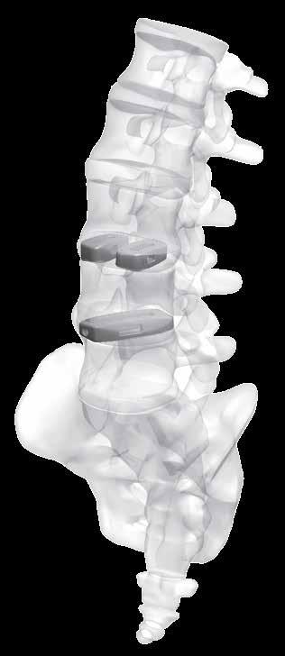
4 MectaLIF Oblique & Posterior Surgical Technique 1. INTRODUCTION The anatomical design of our MectaLIF Intervertebral Body Fusion Device matches the given biological conditions in each patient and pathology and meets the requirements of the treating surgeon. The PLIF procedure, popularized in the 1950 s and 1960 s by Cloward, who inserted iliac crest bone into the intervertebral disc space, lost popularity because of the complication rate and technical difficulties. In the 1980 s spacers made of titanium or carbon fiber reinforced PEEK were designed to overcome these challenges. However, bone from the iliac crest can be adjusted to the patient s anatomy, compared to metal spacers which are available in a predetermined design. These thoughts led us to the development of our MectaLIF Posterior and MectaLIF Oblique Intervertebral Body Fusion Device, whose anatomical design features offer distinctive benefits. Uniform, easy instrumentation for unilateral transforaminal/oblique approach (TLIF) or a bilateral posterior approach (PLIF) Biconvex superior/inferior surface that closely match the native anatomy Different footprints (three) and heights (nine) are offered to address individual patient anatomy The footprint as well as the outer counter is anatomically shaped to facilitate optimal load transfer and maximize the implant-endplate contact surface Large central as well as lateral window to receive filling material (bone graft or substitute) to accelerate the occurrence of fusion through the implant Pyramid shaped teeth to enhance both the implant stability and the resistance to implant migration Shapes ranging from parallel to lordotic to restore natural sagittal alignment Self-distracting bullet nose tip for simplicity of insertion Available in two versions: PEEK, TiPEEK PEEK is radiolucent and optimizes the load transfer between the cage and the adjacent vertebral bodies and reduces the effects of stress shielding on the graft material. TiPEEK, is a titanium coated PEEK cage that combines the features from PEEK with the osteo-conductive features of titanium. 1. MectaLIF Posterior 3. MectaLIF Posterior 2. MectaLIF Oblique 4. MectaLIF Oblique 4


")


5 1.1 MATERIALS & MARKERS Biocompatible radiolucent PEEK with a favorable modulus of elasticity allows a clear assessment of bony fusion Posterior and anterior marker pins (Tantalum or Titanium) allow a easy and clear visualization. 7. OBLIQUE 12mm Ventral/Dorsal Approach MectaLIF Oblique 5. PLIF 11mm Ventral Approach MectaLIF Oblique 6. PLIF 9mm 8. Dorsal Approach MectaLIF Oblique 5
6 MectaLIF Oblique & Posterior Surgical Technique 2. INDICATIONS The MectaLIF Posterior and the Oblique Intervertebral Fusion Device in combination with supplemental pedicle screw fixation are indicated for use with autogenous bone graft in patients with degenerative disc disease (DDD) at one or two contiguous spinal levels from L2 S1 whose condition requires the use of interbody fusion. These patients may have had a previous non-fusion spinal surgery at the involved spinal level(s). The MectaLIF Posterior Intervertebral Body Fusion Device is inserted bilaterally in pairs via posterior lumbar interbody fusion approach. The MectaLIF Oblique Intervertebral Body Fusion Device is inserted unilaterally via transforaminal lumbar interbody fusion approach in either open or minimal invasive technique. 3. CONTRAINDICATIONS The MectaLIF Posterior, MectaLIF Oblique Intervertebral Body Fusion Device System in combination with a pedicle screw system should not be implanted in patients with active systemic infection or infection localized to the site of implantation. 4. PRE-OPERATIVE PLANNING Prior to any surgical implantation of the device, it is ciritical to evaluate the patient s pre-operative MRI and/or CT scan to template and determine the most appropriate size and type of implant to be used so as to match the patient s anatomy. 6
. A conventional discectomy is performed by incising the annulus lateral to the dural sac.")

7 5. SURGICAL TECHNIQUE POSTERIOR - PLIF 5.1 EXPOSURE AND PREPARATION - PLIF Start the skin incision and dissection laterally from the midline. Locate the spinous process and the lamina of the corresponding level(s). A conventional discectomy is performed by incising the annulus lateral to the dural sac. Use the curette to remove the disc through the incision window leaving only the anterior and lateral annulus intact. This is done bilaterally, cosecutively the disc fragments from the intradiscal space are removed with disc rongeurs in standard fashion. The importance of this is to remove extruded fragments, to adequately decompress the neural elements, and to provide entry to the disc space for distraction with minimal or no nerve root retraction. If there is significant disc space collapse, a complete discectomy may not be possible until disc space distraction is accomplished. It is also important to remove osteophytes and posterior lips of the adjacent vertebral body with an osteotome. 9. CAUTION Perform a laminotomy sufficiently large enough for the PLIF preparation. Ensure that the neural structures are protected throughout the entire disc space exposure. The disc space is sequentially distracted until original disc space height is obtained and normal foraminal heights are restored. It is critical to ensure that the segment is not overdistracted. Depending on the pathology and the surgeon s preference there are two other methods to achieve disc space distraction: either via pedicle screws or using a lamina spreader. Remaining soft tissue or cartilaginous endplate are removed with vigorous scraping or curettage, which is essential for good vascularization of the bone graft. Excessive endplate preparation, however, can weaken the endplates and predispose to fracture or device subsidence. It is therefore of paramount importance to remove only the cartilaginous portion of the endplates, and to maintain the integrity of the underlying bony endplate which provides compressive resistance


8 MectaLIF Oblique & Posterior Surgical Technique 5.2 TRIAL INSERTION - PLIF 25mm 22mm 11. PLIF 11mm 13. PLIF 11mm 12. PLIF 9mm The length of the Trial Implants is 25 mm. The notch on the top of the trial indicates 22 mm which is equivalent to the shorter version of the cage. 14. PLIF 9mm Select the size of the Trial Implant as determined during preoperative planning and confirmed by intraoperative fluroscopy and attach it to the dedicated inserter. The inserter for PLIF 9mm can be distinguished from the inserter for PLIF 11mm thanks to the two anterior prongs that match with the posterior grooves of the trial and the proximal gear to lock/unlock the trial/implants. Each inserter must be used only with the related trials. WARNING Markers on the Trials, Inserters and Implants must be aligned to confirm proper engagement of the Trial/Implant with the related inserter. See fig 13 and 14. The Inserter to be used is marked MectaLIF Posterior on the shaft. The mark LATERAL indicates the proper alignment of the instrument in respect to the patient. Insert the Trial Implant into the disc space by light impaction and confirm proper position, depth, and size with intraoperative fluoroscopy and tactile feel. If the Trial Implant is too loose or too tight, try the next larger/smaller size until a secure fit is achieved. Using the largest possible implant improves stability by creating tension on the ligaments and the annulus fibrosus. 15. Remove the Trial Implant assembly and select the matching implant. If necessary, the Slap Hammer / Slotted Hammer is available to assist in safe removal of the Trial Implant. 8


. Insert the implant straight into the intervertebral disc space by gentle impaction. 16.")


9 5.3 IMPLANT PLACEMENT - PLIF Prepare autologous bone graft and / or synthetic bone graft substitute mixed with autologous bone graft and / or freshly aspirated bone marrow; place it at the anterior rim of the vertebral body and impact it gently before inserting the implant. Different Bone Graft Impactors as well as a Bone Tamp are included in the instrument set. Gently pack bone graft and /or synthetic bone graft substitute into the opening of the cage using the Filler Block and Bone Tamp. 18. Engage - Clockwise Disengage - Counter clockwise NOTE: ensure that the orientation of the implant is correct (see marker line on the implant which should line up with the corresponding line on the instrument). Insert the implant straight into the intervertebral disc space by gentle impaction. 16. Attach the implant perpendicular to the Inner Rod / Posterior Handle assembly by screwing the thread of the Inner Rod into the threaded hole and secure it firmly. The cylindrical tip of the Inner Rod simplifies the fixation of the implant. If 9mm PLIF are used, match the prongs of the PLIF 9mm inserter with the implant groves until the mechanical stop. CAUTION Protect the nerve roots and thecal sac with a suitable instrument. Check the position of the implant with the image intensifier. Remove the instrument if the implant position is to your satisfaction. Insert the second implant on the contralateral side as described before. If necessary, lightly tap the implant into position using the Cage Impactor and the Slap Hammer / Slotted Hammer Rotate the proximal gear to lock the implant. 9


10 MectaLIF Oblique & Posterior Surgical Technique 5.4 RADIOGRAPHIC POSITIONING - PLIF Check the position of the implant with the image intensifier. Correct Lateral View: the implant should appear as in the figures below. PLIF 11mm PLIF 11mm 22. AP VIEW 20. Lateral VIEW PLIF 9mm PLIF 9mm 23. AP VIEW 21. Lateral VIEW Check the position of the implant with the image intensifier. Insert the second implant on the contralateral side as described before. If necessary tap lightly the implant into position with the Cage Impactor and the Slap Hammer / Slotted Hammer. Correct AP View. The implant should appear as in the following figures. Remove the instrument if the implant is in satisfactory position. Be careful to ensure proper alignment of the implants. 10


11 6. SURGICAL TECHNIQUE OBLIQUE - OBLIQUE 6.1 EXPOSURE AND PREPARATION - OBLIQUE The OLIF technique can be performed either in open or mini-open approach. tissue, probe with ball point instrument. Gently retract the nerve root and dural tube. Then create the annular window with an annulus knife. To assist distraction during disc space preparation, pedicle screws and rod can be inserted on the contralateral side. Use the curette to remove the disc through the incision window. The annulus must be preserved to provide additional support. A combination of shavers, pituitary rongeurs, and curettes designed for intervertebral discs can facilitate removal of the nucleus pulposus and the surface layers of the cartilaginous endplates. 24. Start the skin incision and dissect laterally from the midline. Locate the spinous process and the lamina of the corresponding layer(s) (A). Prepare a window for the oblique approach, using an osteotome or drill, to remove the inferior facet of the cranial vertebra and the superior facet of the caudal vertebra (B). Ensure that the neural structures are spared as much as possible. Additional bone removal may be carried out using a Kerrison rongeur or drill. The critical steps include adequate removal of extruded disc fragments, adequate decompression of the traversing and exiting nerve roots, and to provide entry to the disc space for distraction with minimal or no nerve root retraction. If there is significant disc space collapse, a complete discectomy may not be possible until disc space distraction is accomplished. WARNING Be sure to remove osteophytes and posterior lips of the adjacent vertebral body with an osteotome so as to avoid neural impingement or graft malalignment. The disc space is sequentially distracted until adequate disc space height is obtained and normal foraminal heights are restored. Insert the shavers with the curved sides touching the endplates. Insert shavers sequentally until the desired height is obtained. WARNING It is critical to ensure that the segment is not overdistracted. Depending on the pathology and the surgeon s preference there are two other methods to achieve disc space distraction: either via pedicle screws or using a lamina spreader. Remaining soft tissue or cartilaginous endplate are removed with vigorous scraping or curettage, which is essential for good vascularization of the bone graft. 25. Divide the ligamentum flavum from the inferior portion of the lamina. Expose the nerve root and dural tube from soft WARNING Excessive endplate preparation, however, can weaken the endplates and predispose to fracture or device subsidence. It is therefore of paramount importance to remove only the cartilaginous portion of the endplates, and to maintain the integrity of the underlying bony endplate which provides compressive resistance. 11
 and P (Posterior)markings to facilitate proper orientation.")


12 MectaLIF Oblique & Posterior Surgical Technique 6.2 TRIAL INSERTION - OBLIQUE mm 32mm 28mm The Trials as well as the implants have A (Anterior) and P (Posterior)markings to facilitate proper orientation. The lenghts of the Trials are 36 mm and the two pair of notches on the Trial indicates 32mm and 28mm, respectively. Each pair of notches are on both side to allow ventral or dorsal access. Select the size of the Trial Implant as determined during preoperative templating and confirmed intraoperatively by fluoroscopy and attach it to the inserter assembly. Insert the Trial Implant into the disc space by light impaction and confirm the proper position with the aid of anterior-posterior and lateral fluoroscopy. If the Trial Implant is too loose or too tight, try the next larger/smaller size until a secure fit is achieved. Using the largest possible implant improves stability by creating tension on the ligaments and the annulus fibrosus. Remove the Trial Implant and select the matching implant. If necessary the Slap Hammer/Slotted Hammer is available to assist in safe removal of the Trial Implant. 6.3 IMPLANT PLACEMENT - OBLIQUE Prepare autologous bone graft and/or synthetic bone graft substitute like MectaGel or MectaBone-G mixed with autologous bone graft and/or freshly aspirated bone marrow; place it anteriorly and contralaterally before inserting the implant. Gently pack bone graft and/or synthetic bone graft substitute into the opening of the selected cage using the filler block and bone tamp. 27. The mark MEDIAL indicates the proper alignment of the instrument in respect to the patient. Visualization of the two holes in the Trial indicate on a true lateral x-ray that the Trial is in the correct position, i.e. 30 in the sagittal plane. The medial mark on the instrument indicates correct alignment. 29. Different shapes of bone graft impactors are available in the set
.")
. Deviation of -5 Deviation of +5 31. 33.")


13 Attach the cage perpendicular to the Oblique Handle /Inner Rod assembly by screwing the thread of the Inner Rod into the threaded hole and secure it firmly. Ensure that the orientation of the implant is correct (see illustration). The cylindrical guiding tip on the Inserter simplifies the engaging of the instrument. The broken line marker indicates the deviation of the implant position (see below). Deviation of -5 Deviation of Insert the implant into the intervertebral disc space by gentle impaction. Correct AP view. The implant should appear as in the image below. NOTE: check the orientation of the medial marking on the Oblique Handle to confirm the correct positioning of the cage. CAUTION Protect the nerve root with a suitable instrument. If necessary tap lightly the implant into position with the Oblique Implant Impactor into position with the Cage Impactor and the Slotted Hammer / Slap Hammer. 6.4 RADIOGRAPHIC POSITIONING - OBLIQUE Check the position of the implant with the image intensifier. 34. AP VIEW Correct Lateral view. The implant should appear as in the image below. Remove the instrument if the implant is in satisfactory position. To achieve satisfactory immobilization of the grafted interbody space compression on the additional posterior fixation with a pedicle screw system is recommended. 32. Lateral VIEW 13


14 MectaLIF Oblique & Posterior Surgical Technique 7. REMOVAL OF AN INCORRECTLY PLACED IMPLANT Attach the Implant Remover or the Oblique Handle/Inner rod assembly perpendicular to the implant and remove the implant from its site. If necessary, the Slap Hammer / Slotted Hammer are available to assist in safe removal of the implant For any further information related to the MectaLIF Intervertebral Body Fusion Devices please refer to the package insert. The MectaLIF Posterior and the MectaLIF Oblique implants are supplied sterile in single-use packages; they should never be re-used. 14
15 8. IMPLANT NOMENCLATURE MECTALIF POSTERIOR TRIAL 11x22MM MECTALIF POSTERIOR TRIAL 11x25MM * 22x7-0 Light Blue * 25x7-0 Light Blue * 22x8-0 Dark Brown * 25x8-0 Dark Brown * 22x9-0 Violet * 25x9-0 Violet * 22x10-0 Silver * 25x10-0 Silver * 22x11-0 Gold * 25x11-0 Gold * 22x12-0 Orange * 25x12-0 Orange * 22x13-0 Dark Blue * 25x13-0 Dark Blue * 22x14-0 Pink * 25x14-0 Pink * 22x15-0 Dark Green * 25x15-0 Dark Green * 22x7-5 Light Blue x7-5 Light Blue * 22x8-5 Dark Brown x8-5 Dark Brown * 22x9-5 Violet x9-5 Violet * 22x10-5 Silver x10-5 Silver * 22x11-5 Gold x11-5 Gold * 22x12-5 Orange x12-5 Orange * 22x13-5 Dark Blue x13-5 Dark Blue * 22x14-5 Pink x14-5 Pink * 22x15-5 Dark Green x15-5 Dark Green * 22x9-10 Violet x9-10 Violet * 22x10-10 Silver x10-10 Silver * 22x11-10 Gold x11-10 Gold * 22x12-10 Orange x12-10 Orange * 22x13-10 Dark Blue x13-10 Dark Blue * 22x14-10 Pink x14-10 Pink * 22x15-10 Dark Green x15-10 Dark Green *Special order / request / special forecast 15
16 MectaLIF Oblique & Posterior Surgical Technique MECTALIF POSTERIOR TRIAL 9x22MM MECTALIF POSTERIOR TRIAL 9x25MM * 22x7-0 Light Blue * 25x7-0 Light Blue * 22x8-0 Dark Brown * 25x8-0 Dark Brown * 22x9-0 Violet * 25x9-0 Violet * 22x10-0 Silver * 25x10-0 Silver * 22x11-0 Gold * 25x11-0 Gold * 22x12-0 Orange * 25x12-0 Orange * 22x13-0 Dark Blue * 25x13-0 Dark Blue * 22x14-0 Pink * 25x14-0 Pink * 22x15-0 Dark Green * 25x15-0 Dark Green * 22x7-5 Light Blue x7-5 Light Blue * 22x8-5 Dark Brown x8-5 Dark Brown * 22x9-5 Violet x9-5 Violet * 22x10-5 Silver x10-5 Silver * 22x11-5 Gold x11-5 Gold * 22x12-5 Orange x12-5 Orange * 22x13-5 Dark Blue x13-5 Dark Blue * 22x14-5 Pink x14-5 Pink * 22x15-5 Dark Green x15-5 Dark Green * 22x9-10 Violet x9-10 Violet * 22x10-10 Silver x10-10 Silver * 22x11-10 Gold x11-10 Gold * 22x12-10 Orange x12-10 Orange * 22x13-10 Dark Blue x13-10 Dark Blue * 22x14-10 Pink x14-10 Pink * 22x15-10 Dark Green x15-10 Dark Green * 22x13-15 Dark Blue * 25x14-15 Pink * 22x14-15 Pink * 25x15-15 Dark Green * 22x15-15 Dark Green * 22x14-15 Pink * 25x15-20 Dark Green * 22x15-15 Dark Green *Special order / request / special forecast 16
17 MECTALIF OBLIQUE TRIAL x7-0 Light Blue x8-0 Dark Brown * 25x9-0 Violet * 25x10-0 Silver * 25x11-0 Gold * 25x12-0 Orange * 25x13-0 Dark Blue * 25x14-0 Pink * 25x15-0 Dark Green x7-5 Light Blue x8-5 Dark Brown x9-5 Violet x10-5 Silver x11-5 Gold x12-5 Orange x13-5 Dark Blue x12-10 Orange x13-10 Dark Blue x14-10 Pink x15-10 Dark Green * 28x11-10 Gold *Special order / request / special forecast 17

18 MectaLIF Oblique & Posterior Surgical Technique MECTALIF POSTERIOR PEEK 11MM L W H * 11x22x * 11x25x * 11x22x * 11x25x * 11x22x * 11x25x * 11x22x * 11x25x * 11x22x * 11x25x * 11x22x * 11x25x * 11x22x * 11x25x * 11x22x * 11x25x * 11x22x * 11x25x x22x x25x x22x x25x x22x x25x x22x x25x x22x x25x x22x x25x x22x x25x x22x x25x x22x x25x x22x x25x x22x x25x x22x x25x x22x x25x x22x x25x x22x x25x x22x x25x15 10 *Special order / request / special forecast 18
19 MECTALIF POSTERIOR PEEK 9MM L W H * 9x22x * 9x25x * 9x22x * 9x25x * 9x22x * 9x25x * 9x22x * 9x25x * 9x22x * 9x25x * 9x22x * 9x25x * 9x22x * 9x25x * 9x22x * 9x25x * 9x22x * 9x25x x22x x25x x22x x25x x22x x25x x22x x25x x22x x25x x22x x25x x22x x25x x22x x25x x22x x25x x22x x25x x22x x25x x22x x25x x22x x25x x22x x25x x22x x25x x22x x25x * 9x22x * 9x25x * 9x22x * 9x25x * 9x22x * 9x25x * 9x22x * 9x22x15 20 *Special order / request / special forecast 19

20 MectaLIF Oblique & Posterior Surgical Technique MECTALIF POSTERIOR TIPEEK 11MM L W H * 11x22x * 11x25x * 11x22x * 11x25x * 11x22x * 11x25x * 11x22x * 11x25x * 11x22x * 11x25x * 11x22x * 11x25x * 11x22x * 11x25x * 11x22x * 11x25x * 11x22x * 11x25x x22x x25x x22x x25x x22x x25x x22x x25x x22x x25x x22x x25x x22x x25x x22x x25x x22x x25x x22x x25x x22x x25x x22x x25x x22x x25x x22x x25x x22x x25x x22x x25x15 10 *Special order / request / special forecast 20

21 MECTALIF POSTERIOR TIPEEK 9MM L W H * 9x22x * 9x25x * 9x22x * 9x25x * 9x22x * 9x25x * 9x22x * 9x25x * 9x22x * 9x25x * 9x22x * 9x25x * 9x22x * 9x25x * 9x22x * 9x25x * 9x22x * 9x25x x22x x25x x22x x25x x22x x25x x22x x25x x22x x25x x22x x25x x22x x25x x22x x25x x22x x25x x22x x25x x22x x25x x22x x25x x22x x25x x22x x25x x22x x25x x22x x25x * 9x22x * 9x25x * 9x22x * 9x25x * 9x22x * 9x25x * 9x22x * 9x22x15 20 *Special order / request / special forecast 21
22 MectaLIF Oblique & Posterior Surgical Technique MECTALIF OBLIQUE PEEK L W H x28x x28x * 12x28x * 12x28x * 12x28x * 12x28x * 12x28x * 12x28x * 12x28x x28x x28x x28x x28x x28x x28x x28x x28x x28x x28x x28x x28x x32x x32x * 12x32x * 12x32x * 12x32x * 12x32x * 12x32x * 12x32x * 12x32x15 0 *Special order / request / special forecast x32x x32x x32x x32x x32x x32x x32x x32x x32x x32x x32x x36x x36x * 12x36x * 12x36x * 12x36x * 12x36x * 12x36x * 12x36x * 12x36x x36x x36x x36x x36x x36x x36x x36x x36x x36x x36x x36x

23 MECTALIF OBLIQUE TIPEEK L W H x28x x28x * 12x28x * 12x28x * 12x28x * 12x28x * 12x28x * 12x28x * 12x28x x28x x28x x28x x28x x28x x28x x28x x28x x28x x28x x28x x28x x32x x32x * 12x32x * 12x32x * 12x32x * 12x32x * 12x32x * 12x32x * 12x32x15 0 *Special order / request / special forecast x32x x32x x32x x32x x32x x32x x32x x32x x32x x32x x32x x36x x36x * 12x36x * 12x36x * 12x36x * 12x36x * 12x36x * 12x36x * 12x36x x36x x36x x36x x36x x36x x36x x36x x36x x36x x36x x36x
24 MectaLIF Oblique & Posterior Surgical Technique 9. RECOMMENDED FIXATION OPTIONS Supplemental internal fixation e.g. pedicle screw fixation must be applied. 24
25 NOTES 25
26 MectaLIF Oblique & Posterior Surgical Technique 26
27 Part numbers subject to change. NOTE FOR STERILISATION The instrumentation is not sterile upon delivery. It must be cleaned before use and sterilised in an autoclave in accordance with the regulations of the country, EU directives where applicable and following the instructions for use of the autoclave manufacturer. For detailed instructions please refer to the document Recommendations for cleaning decontamination and sterilisation of Medacta International orthopaedic devices available at 27

28 Medacta International SA Strada Regina Castel San Pietro - Switzerland Phone Fax info@medacta.ch Find your local dealer at: medacta.com/locations All trademarks and registered trademarks are the property of their respective owners. MectaLIF Oblique & Trasforaminal Surgical Technique ref: rev. 09 Last update: May
ectalif O BLIQUE & POSTERIOR
 ectalif O BLIQUE & POSTERIOR INTERVERTEBRAL BODY FUSION DEVICE Surgical Technique Hip Knee Spine Navigation MectaLIF Oblique & Posterior Surgical Technique Hip Knee Spine Navigation CAUTION Federal law
ectalif OBLIQUE & POSTERIOR
 ectalif OBLIQUE & POSTERIOR INTERVERTEBRAL BODY FUSION DEVICE Surgical Technique Hip Knee Spine Navigation MectaLIF Oblique & Posterior Surgical Technique Hip Knee Spine Navigation ACKNOWLEDGEMENTS Medacta
Royal Oak IBFD System Surgical Technique Posterior Lumbar Interbody Fusion (PLIF)
") Royal Oak IBFD System Surgical Technique Posterior Lumbar Interbody Fusion (PLIF) Preoperative Planning Preoperative planning is necessary for the correct selection of lumbar interbody fusion devices.
Royal Oak IBFD System Surgical Technique Posterior Lumbar Interbody Fusion (PLIF) Preoperative Planning Preoperative planning is necessary for the correct selection of lumbar interbody fusion devices.
Alamo T Transforaminal Lumbar Interbody System Surgical Technique
 Transforaminal Lumbar Interbody System Surgical Technique Table of Contents Indications and Device Description.............. 1 Alamo T Implant Features and Instruments...........2 Surgical Technique......................
Interbody fusion cage for the transforaminal approach. Travios. Surgical Technique
 Interbody fusion cage for the transforaminal approach Travios Surgical Technique Image intensifier control This description alone does not provide sufficient background for direct use of DePuy Synthes
Posterior Lumbar Interbody Fusion System
 Px Posterior Lumbar Interbody Fusion System Px PEEK INTERBODY FUSION SYSTEM INDICATIONS FOR USE The Innovasis Px PEEK IBF System is an intervertebral body fusion device for use in patients with degenerative
MODULAR DESIGN OFFERS FREEDOM OF CHOICE. Surgical Technique
 MODULAR DESIGN OFFERS FREEDOM OF CHOICE Surgical Technique Joint Spine Sports Med MectaLIF Anterior Surgical Technique 2 INDEX 1. INTRODUCTION 4 1.1 Material & Marker 5 2. INDICATIONS 5 3. CONTRAINDICATIONS
SURGICAL TECHNIQUE MANUAL. InterFuse T
 1 CONTENTS InterFuse T Product Description 3 Indications for Use 3 X-Ray Marker Locations 4 Product Specifications 4 Instrument Set 5 Step 1 Preoperative Planning 8 Patient Positioning 8 Step 2 Disc Removal
M.I.S. MAKE IT SMART IN ONE SYSTEM. Surgical Technique. Hip Knee Spine Navigation
 M.I.S. MAKE IT SMART IN ONE SYSTEM Surgical Technique Hip Knee Spine Navigation M.U.S.T. Mini Open Surgical Technique Hip Knee Spine Navigation 2 C O N T E N T S 1 INTRODUCTION 4 2 SURGICAL TECHNIQUE 5
VTI INTERFUSE T SURGICAL TECHNIQUE FORWARD THINKING FOR THE BACK. 1/20
 VTI INTERFUSE T SURGICAL TECHNIQUE FORWARD THINKING FOR THE BACK. 1/20 CONTENTS InterFuse T Product Description Indications for Use X-Ray Marker Locations Product Specifications Instrument Set 3 4 5 STEP
LUMBAR POSTERIOR MINIMALLY INVASIVE SYSTEM. Surgical Technique
 LUMBAR POSTERIOR MINIMALLY INVASIVE SYSTEM Surgical Technique Joint Spine Sports Med M.U.S.T. Mini Open Surgical Technique Joint Spine Sports Med CAUTION Federal law (USA) restricts this device to sale
nvp Posterior Lumbar Interbody Fusion System
 nvp Posterior Lumbar Interbody Fusion System 1 IMPORTANT INFORMATION FOR PHYSICIANS, SURGEONS, AND/OR STAFF The nv a, nv p, and nv t are an intervertebral body fusion device used in the lumbar spine following
Surgical Technique. Apache Posterior Lumbar Interbody Fusion Apache Transforaminal Lumbar Interbody Fusion
 Surgical Technique Apache Posterior Lumbar Interbody Fusion Apache Transforaminal Lumbar Interbody Fusion 2 Table of Contents Page Preoperative Planning 4 Patient Positioning 5 Disc Exposure 5 Disc and
ectalif T RANSFORAMINAL
 ectalif T RANSFORAMINAL INTERVERTEBRAL BODY FUSION DEVICE Surgical Technique Hip Knee Spine Navigation MectaLIF Transforaminal Surgical Technique Hip Knee Spine Navigation ACKNOWLEDGEMENTS Medacta International
Alamo C. Cervical Interbody System Surgical Technique. An Alliance Partners Company
 Cervical Interbody System Surgical Technique Table of Contents Indications for Use................................1 Device Description............................... 1 Alamo C Instruments..............................
nvt Transforaminal Lumbar Interbody Fusion System
 nvt Transforaminal Lumbar Interbody Fusion System 1 IMPORTANT INFORMATION FOR PHYSICIANS, SURGEONS, AND/OR STAFF The nv a, nv p, and nv t are an intervertebral body fusion device used in the lumbar spine
Surgical technique. SynCage-C short
 Surgical technique SynCage-C short Table of contents Implants 2 Indications/contra-indications 3 Surgical technique 4 Image intensifier control Warning This description is not sufficient for immediate
nva Anterior Lumbar Interbody Fusion System
 nva Anterior Lumbar Interbody Fusion System 1 IMPORTANT INFORMATION FOR PHYSICIANS, SURGEONS, AND/OR STAFF The nv a, nv p, and nv t are an intervertebral body fusion device used in the lumbar spine following
EIT TLIF Cage. For Natural Bone Ingrowth with EIT Cellular Titanium
 EIT TLIF Cage For Natural Bone Ingrowth with EIT Cellular Titanium EIT TLIF Cage Surgical Technique EIT Cellular Titanium provides active fusion area» ~ 80% porosity» ~ 650 µm diamond pore size» open interconnected
Surgical Technique Manual
 InterFuse S Interbody Fusion System Surgical Technique Manual VERTEBRAL TECHNOLOGIES MS 4043-02 Rev. O Product Overview Introduction The VTI InterFuse S implant is an interbody fusion device that combines
T.L.I.F. Surgical Technique. Featuring the T.L.I.F. SG Instruments, VG2 PLIF Allograft, and the MONARCH Spine System.
 Surgical Technique T.L.I.F. Transforaminal Lumbar Interbody Fusion Featuring the T.L.I.F. SG Instruments, VG2 PLIF Allograft, and the MONARCH Spine System. CONSULTING SURGEON Todd Albert, M.D. Rothman
C-THRU Anterior Spinal System
 C-THRU Anterior Spinal System Surgical Technique Manufactured From Contents Introduction... Page 1 Design Features... Page 2 Instruments... Page 3 Surgical Technique... Page 4 Product Information... Page
VTI INTERFUSE S SURGICAL TECHNIQUE FORWARD THINKING FOR THE BACK.
 VTI INTERFUSE S SURGICAL TECHNIQUE FORWARD THINKING FOR THE BACK. CONTENTS InterFuse S Product Description Indications for Use X-Ray Marker Locations and Product Specifications Instrument Set 3 4 5-7 STEP
Transforaminal Lumbar Interbody Fusion Cage (TLIF)
") Transforaminal Lumbar Interbody Fusion age (TLIF) 990100010 DOULE ENGINE MEDIL MTERIL O., LTD. No. 218 Houxiang Road, Haicang District, Xiamen 361022, P.R.hina Tel: +86 592 6087101 Fax: +86 592 6587078
Transforaminal Lumbar Interbody Fusion age (TLIF) 990100010 DOULE ENGINE MEDIL MTERIL O., LTD. No. 218 Houxiang Road, Haicang District, Xiamen 361022, P.R.hina Tel: +86 592 6087101 Fax: +86 592 6587078
EFSPINE CERVICAL COMBINED SET DISC PROTHESIS ORGANIZER BOX
 EFSPINE CERVICAL COMBINED SET INSTRUMENTS CERVICAL CAGE & DISC PROTHESIS ORGANIZER BOX Cervical Thoracic Thoraco - Lumbar Sacral EFSPINE CERVICAL COMBINED SET CERVICAL IMPLANTS INTRODUCTION Cervical Disc
PEEK Cage for Posterior Lumbar Interbody Fusion (PLIF) Plivios Revolution. Surgical Technique
 Plivios Revolution. Surgical Technique") PEEK Cage for Posterior Lumbar Interbody Fusion (PLIF) Plivios Revolution Surgical Technique Image intensifier control This description alone does not provide sufficient background for direct use of DePuy
PEEK Cage for Posterior Lumbar Interbody Fusion (PLIF) Plivios Revolution Surgical Technique Image intensifier control This description alone does not provide sufficient background for direct use of DePuy
Apache Cervical Interbody Fusion Device. Surgical Technique. Page of 13. LC-005 Rev F
 LC-005 Rev F Apache Cervical Interbody Fusion Device Page of 13 Surgical Technique INDICATIONS: When used as an intervertebral body fusion device, the Genesys Spine Interbody Fusion System is indicated
SynCage-C short. Surgical Technique. This publication is not intended for distribution in the USA.
 SynCage-C short Surgical Technique This publication is not intended for distribution in the USA. Instruments and implants approved by the AO Foundation. Table of contents Implants 2 Indications/contra-indications
Surgical Technique INTERSOMATIC CERVICAL CAGE
 R INTERSOMATIC CERVICAL CAGE NEOCIF IMPLANTS NEOCIF is an implant designed to make anterior cervical interbody fusion (ACIF) easier and to remove the need for structural autologous graft. The cage is made
Advantage ALIF. Keith Shevlin Managing Director
 Advantage ALIF Unit 10, 9-11 Myrtle Street, Crows Nest NSW 2065 Keith Shevlin Managing Director keithshevlin@precisionsurgical.com.au Advantage ALIF Introduction & Indications for Use 1 Surgical Technique
T.L.I.F. Transforaminal Lumbar Interbody Fusion
 T.L.I.F. Transforaminal Lumbar Interbody Fusion Cover Surgical Header Technique Sub Guide header Introduction (T.L.I.F. ) technique has gained wide acceptance Additionally, the T.L.I.F. procedure avoids
Luminary ALIF. Disc preparation and implant insertion instruments.
 Luminary ALIF. Disc preparation and implant insertion instruments. Technique Guide Instruments and implants approved by the AO Foundation Table of Contents Introduction Luminary ALIF 2 AO Principles 4
Solitaire Anterior Spinal System
 Surgical Technique Solitaire Anterior Spinal System Independent Stabilization for the Anterior Column Available in Titanium and Contents Introduction... Page 1 Design Features... Page 2 Instruments...
TABLE OF CONTENTS. ShurFit Anterior Cervical Interbody Fusion (ACIF) System Overview 2. Implant Specifications 3. Instrument Features 4
 System Overview 2. Implant Specifications 3. Instrument Features 4") Surgical Technique TABLE OF CONTENTS ShurFit Anterior Cervical Interbody Fusion (ACIF) System Overview 2 Product Highlights 2 Indications 2 Implant Specifications 3 Instrument Features 4 Surgical Technique
Surgical Technique TABLE OF CONTENTS ShurFit Anterior Cervical Interbody Fusion (ACIF) System Overview 2 Product Highlights 2 Indications 2 Implant Specifications 3 Instrument Features 4 Surgical Technique
The Fusion of. Strength, Design. Performance. and
 The Fusion of Strength, Design and Performance Interbody Fusion Platform Interbody Fusion Platform The DePuy Spine Interbody Fusion platform is designed to provide an open architecture implant in a load-sharing
Surgical Technique. TraXis. Precision. Transforaminal Lumbar Interbody Fusion Spacer. The Art & Science of Spine Surgery
 Surgical Technique Precision TraXis Transforaminal Lumbar Interbody Fusion Spacer The Art & Science of Spine Surgery Table of Contents Introduction 3 Indications 4 Key Instruments 5 Surgical Technique
SynCage. Surgical Technique. This publication is not intended for distribution in the USA. Instruments and implants approved by the AO Foundation.
 SynCage Surgical Technique This publication is not intended for distribution in the USA. Instruments and implants approved by the AO Foundation. Image intensifier control Warning This description alone
PILLAR AL. Anterior Lumbar Interbody Fusion (ALIF) and Partial Vertebral Body Replacement (pvbr) PEEK Spacer System OPERATIVE TECHNIQUE
 and Partial Vertebral Body Replacement (pvbr) PEEK Spacer System OPERATIVE TECHNIQUE") PILLAR AL PEEK Spacer System Anterior Lumbar Interbody Fusion (ALIF) and Partial Vertebral Body Replacement (pvbr) OPERATIVE TECHNIQUE Table of Contents 1 INTRODUCTION 2 PRE-OPERATIVE TECHNIQUE 3 OPERATIVE
PILLAR AL PEEK Spacer System Anterior Lumbar Interbody Fusion (ALIF) and Partial Vertebral Body Replacement (pvbr) OPERATIVE TECHNIQUE Table of Contents 1 INTRODUCTION 2 PRE-OPERATIVE TECHNIQUE 3 OPERATIVE
T-PAL. Transforaminal Posterior Atraumatic Lumbar Cage System.
 T-PAL. Transforaminal Posterior Atraumatic Lumbar Cage System. Technique Guide This publication is not intended for distribution in the USA. Instruments and implants approved by the AO Foundation. Image
Technique Guide. StenoFix. Interspinous distraction after surgical decompression.
 Technique Guide StenoFix. Interspinous distraction after surgical decompression. Table of Contents Introduction StenoFix 2 Indications and Contraindications 4 Surgical Technique Preoperative Planning
Technique Guide. T-PAL. Transforaminal posterior atraumatic lumbar spacer system.
 Technique Guide T-PAL. Transforaminal posterior atraumatic lumbar spacer system. Table of Contents Introduction T-PAL 2 AO Principles 4 Indications and Contraindications 5 Surgical Technique Preparation
CROSS -FUSE P E E K V B R / I B F SYST E M
 S U R G I C A L T E C H N I Q U E CROSS -FUSE P E E K V B R / I B F SYST E M S U R G I C A L S Y S T E M O V E R V I E W 2 CROSS-FUSE P E E K V B R / I B F S Y S T E M S U R G I C A L T E C H N I Q U E
Plivios and Plivios chronos. Radiolucent cage system for posterior lumbar interbody fusion.
 Plivios and Plivios chronos. Radiolucent cage system for posterior lumbar interbody fusion. Surgical Technique This publication is not intended for distribution in the USA. Instruments and implants approved
SYNCAGE EVOLUTION. This publication is not intended for distribution in the USA. SURGICAL TECHNIQUE
 SYNCAGE EVOLUTION This publication is not intended for distribution in the USA. SURGICAL TECHNIQUE Image intensifier control Warning This description alone does not provide sufficient background for direct
L-VARLOCK. Posterior Lumbar Cage with adjustable lordosis. S urgical T echnique
 L-VARLOCK Posterior Lumbar Cage with adjustable lordosis S urgical T echnique Introduction Designed and manufactured by KISCO International, L-VARLOCK cages are made of titanium alloy Ti 6AI 4V (standards
ONE SYSTEM, MULTIPLE OPTIONS. Surgical Technique. Hip Knee Spine Navigation
 ONE SYSTEM, MULTIPLE OPTIONS Surgical Technique Hip Knee Spine Navigation MUST MINI Surgical Technique Hip Knee Spine Navigation INTRODUCTION The M.U.S.T. Mini posterior cervical screw system is a modular
product overview Implant heights range from 8mm-20mm in 2mm increments, with two lordocic angle options of 6 and 12.
 ETHOS A-Spacer PEEK System Surgical Technique Guide Synchronizing Medical Innovation with Global Markets product overview The SyncMedical Ethos PEEK IBF System is an intervertebral body fusion device for
XRL A modular expandable radiolucent vertebral body replacement system
 XRL A modular expandable radiolucent vertebral body replacement system This publication is not intended for distribution in the USA. SURGICAL TECHNIQUE Table of Contents Introduction XRL 2 AO Spine Principles
HawkeyeTM Peek. surgical technique
 HawkeyeTM Peek surgical technique Introduction The ChoiceSpine HAWKEYE Vertebral Body Replacement (VBR) System is intended for use in the thoracolumbar spine (T1 - L5) to replace a collapsed, damaged,
Fusion Device. Surgical Technique. Cervical Interbody Fusion with Trabecular Metal Technology
 TM-S Fusion Device Surgical Technique Cervical Interbody Fusion with Trabecular Metal Technology 2 TM-S Fusion Device Surgical Technique Disclaimer This surgical technique is not intended for use in the
UNIQUE ANATOMIES PATIENT-MATCHED SOLUTIONS. Surgical Technique
 UNIQUE ANATOMIES PATIENT-MATCHED SOLUTIONS Surgical Technique Joint Spine Sports Med MySpine Surgical Technique Joint Spine Sports Med 2 INTRODUCTION MySpine is a patient matched, pedicle targeted technology
.U.S.T. MINI OPEN. Surgical Technique LUMBAR POSTERIOR MINIMALLY INVASIVE SYSTEM. Hip Knee Spine Navigation
 .U.S.T. MINI OPEN LUMBAR POSTERIOR MINIMALLY INVASIVE SYSTEM Surgical Technique Hip Knee Spine Navigation M.U.S.T. Mini Open Surgical Technique Hip Knee Spine Navigation CAUTION Federal law (USA) restricts
Imola Lateral IBF System Surgical Technique
 Imola Lateral IBF System Surgical Technique IMOLA CIRCUIT TABLE OF CONTENTS Design Rationale Instructions for Use Surgical Technique 1. Table Mounting 2. Surgical Planning & Targeting 3. Access and Preparation
Module: #15 Lumbar Spine Fusion. Author(s): Jenni Buckley, PhD. Date Created: March 27 th, Last Updated:
: Jenni Buckley, PhD. Date Created: March 27 th, Last Updated:") Module: #15 Lumbar Spine Fusion Author(s): Jenni Buckley, PhD Date Created: March 27 th, 2011 Last Updated: Summary: Students will perform a single level lumbar spine fusion to treat lumbar spinal stenosis.
Module: #15 Lumbar Spine Fusion Author(s): Jenni Buckley, PhD Date Created: March 27 th, 2011 Last Updated: Summary: Students will perform a single level lumbar spine fusion to treat lumbar spinal stenosis.
BAK/C Cervical Anterior Interbody Fusion System
 Surgical Technique BAK/C Cervical Anterior Interbody Fusion System The Comfortable Choice for Cervical Fusion BAK/C Cervical Surgical Technique 1 The BAK/C Cervical Fusion System is an alternative to conventional
Ardis. Surgical Technique. Interbody System. Solutions by the people of Zimmer Spine. zimmerspine.com
 Ardis Interbody System Surgical Technique Solutions by the people of Zimmer Spine. zimmerspine.com A more advanced interbody solution. From the people of Zimmer Spine. The easily inserted Ardis Interbody
EXACTECH SPINE. Operative Technique. Cervical Spacer System. Surgeon focused. Patient driven. TM
 EXACTECH SPINE Operative Technique Cervical Spacer System Surgeon focused. Patient driven. TM ACAPELLA ONE Acapella One Cervical Spacer System is an anterior cervical discectomy and fusion device with
Cervical Solutions. Optio-C Anterior Cervical Plate. with Allograft/Autograft. Surgical Technique Guide
 Cervical Solutions Optio-C Anterior Cervical Plate with Allograft/Autograft Surgical Technique Guide 2 Optio-C Anterior Cervical Plate with Allograft/Autograft Surgical Technique Guide The Optio-C System
Thoracolumbar Solutions. Zyston Curve. Interbody Spacer System. Surgical Technique Guide
 Thoracolumbar Solutions Zyston Curve Interbody Spacer System Surgical Technique Guide 2 Zyston Curve Interbody Spacer System Surgical Technique Guide The Zyston Curve Interbody System is designed to optimize
OPERATIVE TECHNIQUE. CONSTRUX Mini PTC. Mini PTC Spacer System
 OPERATIVE TECHNIQUE CONSTRUX Mini PTC Mini PTC Spacer System TABLE OF CONTENTS Introduction 1 Operative Technique 2 Part Numbers 6 Indications For Use 7 INTRODUCTION 1 INTRODUCTION The CONSTRUX Mini PTC
Contact Fusion Cage. Surgical Technique
 Contact Fusion Cage Surgical Technique Image intensifier control This description alone does not provide sufficient background for direct use of DePuy Synthes products. Instruction by a surgeon experienced
TABLE OF CONTENTS. Vault C Anterior Cervical Discectomy 2 and Fusion (ACDF) System Overview. Implants 3. Instruments 5. Surgical Technique 10
 System Overview. Implants 3. Instruments 5. Surgical Technique 10") Surgical Technique TABLE OF CONTENTS Vault C Anterior Cervical Discectomy 2 and Fusion (ACDF) System Overview Indications 2 Implants 3 Instruments 5 Surgical Technique 10 1. Preoperative planning 10 2.
Surgical Technique TABLE OF CONTENTS Vault C Anterior Cervical Discectomy 2 and Fusion (ACDF) System Overview Indications 2 Implants 3 Instruments 5 Surgical Technique 10 1. Preoperative planning 10 2.
SYNFIX EVOLUTION SECURED SPACER SYSTEM
 SYNFIX EVOLUTION SECURED SPACER SYSTEM Instruments and implants for stand-alone anterior lumbar interbody fusion Instruments and implants approved by the AO Foundation. This publication is not intended
The Implant. (Klappen außen sind nur 192 mm breit!)
") SEMIAL product information The Implant SEMIAL implants are designed to restore interbody vertebral disc height and maintain solid bony fusion when used in conjunction with bone graft material and supportive
SEMIAL product information The Implant SEMIAL implants are designed to restore interbody vertebral disc height and maintain solid bony fusion when used in conjunction with bone graft material and supportive
Technique Guide. Zero-P VA. Variable angle zero-profile anterior cervical interbody fusion (ACIF) device.
 device.") Technique Guide Zero-P VA. Variable angle zero-profile anterior cervical interbody fusion (ACIF) device. Image intensifier control Warning This description alone does not provide sufficient background
Technique Guide Zero-P VA. Variable angle zero-profile anterior cervical interbody fusion (ACIF) device. Image intensifier control Warning This description alone does not provide sufficient background
Silverstone Interbody System Surgical Technique
 Silverstone Interbody System Surgical Technique TABLE OF CONTENTS Design Rationale Instructions for Use Surgical Technique 1. Disc Space Preparation 2. Distraction 3. Implant Selection 4. Implant Placement
AVS ARIA TM Product Overview
 AVS ARIA TM Product Overview Table of Contents Indication 3 Adaptive Sizing 4-5 Wedge Nose Design 6 Graft Volumes 7 Efficient Fixation 8 Lordotic Descriptions 9 Anatomical Descriptions 10 Visualization
Commander Cervical Cage - SURGICAL TECHNIQUE
 Commander Cervical Cage - SURGICAL TECHNIQUE D e s i g n e d to c l o s e l y f i t yo u! Commander Cervical Cage - SURGICAL TECHNIQUE Indications Commander cervical cages are designed primarly for restoring
SURGICAL TECHNIQUE ROI-T TM TLIF INTERSOMATIC IMPLANT TRANS-FORAMINAL APPROACH
 TLIF INTERSOMATIC IMPLANT TRANS-FORAMINAL APPROACH Table of Contents page Step 1 - Articular resection.................................................................................. 3 Step 2 - Pedicle
Apache Interbody Surgical Technique. LC004 Rev F
 LC004 Rev F Apache Interbody Surgical Technique Apache Anterior Lumbar Interbody Fusion Surgical Technique INDICATIONS: When used as an intervertebral body fusion device, the Genesys Spine Interbody Fusion
Aesculap Spine T-Space PEEK. Transforaminal Lumbar Interbody Fusion System
 Aesculap Spine T-Space PEEK Transforaminal Lumbar Interbody Fusion System Forword Growing socio-economic pressure in conjunction with the high incidence of spinal disorders and consequent conditions calls
Cervical Spacer System surgical technique
 Blackhawk TM Cervical Spacer System surgical technique Blackhawk TM The BLACKHAWK Cervical Spacer System is designed to provide biomechanical stabilization as an adjunct to fusion. Spinal fixation should
GIZA Surgical Technique
 GIZA Surgical Technique Vertebral Body Replacement System Manufactured by Titanium alloy material provides mechanical integrity during insertion and distraction, x-ray visibility, and biocompatibility*
Thoracolumbar Solutions. TM Ardis. Interbody System. Surgical Technique Guide
 Thoracolumbar Solutions TM Ardis Interbody System Surgical Technique Guide 2 TM Ardis Interbody System Surgical Technique Guide Trabecular Metal Technology TM Ardis Interbody System Surgical Technique
Replacement Device A modular expandable radiolucent vertebral body replacement system
 XRL Vertebral Body Replacement Device A modular expandable radiolucent vertebral body replacement system SURGICAL TECHNIQUE TABLE OF CONTENTS Introduction XRL System 2 AO Principles 5 Indications and Contraindications
Synex System TECHNIQUE GUIDE. An expandable vertebral body replacement device
 Synex System TECHNIQUE GUIDE An expandable vertebral body replacement device Original Instruments and Implants of the Association for the Study of Internal Fixation AO ASIF Synex System Overview The Synex
Lumbar Interbody System. Surgical Technique. for Transforaminal Lumbar Interbody Fusion (TLIF)
") Lumbar Interbody System Surgical Technique for Transforaminal Lumbar Interbody Fusion (TLIF) introduction An adaption of the posterior lumbar interbody fusion (PLIF) procedure, the TLIF technique employs
Lumbar Interbody System Surgical Technique for Transforaminal Lumbar Interbody Fusion (TLIF) introduction An adaption of the posterior lumbar interbody fusion (PLIF) procedure, the TLIF technique employs
MEDACTA UNCONSTRAINED SCREW TECHNOLOGY - REDUCTION SCREWS. Surgical Technique. Hip Knee Spine Navigation
 .U.S.T. MEDACTA UNCONSTRAINED SCREW TECHNOLOGY - REDUCTION SCREWS Hip Knee Spine Navigation M.U.S.T. Hip Knee Spine Navigation INTRODUCTION The Medacta Unconstrained Screw Technology [M.U.S.T.] Pedicle
100 Interpace Parkway Parsippany, NJ
 100 Interpace Parkway Parsippany, NJ 07054 www.biometspine.com 800-526-2579 All trademarks are the property of Biomet, Inc. or one of its subsidiaries, unless otherwise indicated. Rx Only. 2009 EBI, LLC.
O.I.C. PEEK UniLIF Unilateral Lumbar Interbody Fusion
 O.I.C. PEEK UniLIF Unilateral Lumbar Interbody Fusion A new implant for an evolving procedure Unique wedge nose Adaptive longer sizing Large internal graft volume Introduction Stryker Spine enters a new
TECHNICAL BROCHURE. Capture Facet Fixation System
 TECHNICAL BROCHURE Capture Facet Fixation System Table of Contents Product Overview...2 Instruments...4 Capture Facet Screw Surgical Technique Patient Preparation and Positioning...6 Guide Pin Placement...7
VLIFT System Overview. Vertebral Body Replacement System
 VLIFT System Overview Vertebral Body Replacement System VLIFT System System Description The VLIFT Vertebral Body Replacement System consists of a Distractible In Situ (DIS) implant, which enables the surgeon
ACIS Anterior Cervical Interbody Spacer
 Implants and Instruments for Interbody Fusion Available in both PEEK and ProTi 360º Titanium Integrated Technology ACIS Anterior Cervical Interbody Spacer Surgical Technique Image intensifier control This
Thoracolumbar Solutions. Avenue T. TLIF Cage. with ertebridge PLATING TECHNOLOGY. Surgical Technique Guide
 Thoracolumbar Solutions Avenue T TLIF Cage with ertebridge PLATING TECHNOLOGY Surgical Technique Guide 2 Avenue T TLIF Cage Surgical Technique VerteBRIDGE Plating is the integrated fixation designed specifically
5/19/2017. Interspinous Process Fixation with the Minuteman G3. What is the Minuteman G3. How Does it Work?
 Interspinous Process Fixation with the Minuteman G3 LLOYDINE J. JACOBS, MD CASTELLVI SPINE MEETING MAY 13, 2017 What is the Minuteman G3 The world s first spinous process plating system that is: Minimally
Technique Guide. ARCH Laminoplasty System. Dedicated System for Open-door Laminoplasty.
 Technique Guide ARCH Laminoplasty System. Dedicated System for Open-door Laminoplasty. Table of Contents Introduction Overview 2 AO ASIF Principles 4 Indications and Contraindications 5 Product Information
PPS P I N P O S I T I O N I N G S Y S T E M GMK EFFICIENCY VERSION. Hip Knee Spine Navigation
 PPS P I N P O S I T I O N I N G S Y S T E M D ESIGNED FOR YOU BY YOU GMK EFFICIENCY VERSION Surgical Surgical Technique Hip Knee Spine Navigation MyKnee Surgical Technique Hip Knee Spine Navigation I N
OPERATIVE TECHNIQUE PTC PEEK FORZA. spacer system
 OPERATIVE TECHNIQUE PTC PEEK FORZA spacer system TABLE OF CONTENTS Introduction 1 Operative Technique 2 Instruments 12 FORZA PEEK Part Numbers 20 FORZA PTC Part Numbers 22 Modular Implant Inserter 24 Disassembly
T-PAL Spacer System. Transforaminal posterior atraumatic lumbar spacer system.
 T-PAL Spacer System. Transforaminal posterior atraumatic lumbar spacer system. One instrument, one technique Accommodates both open and MIS approaches A PEEK implant that works with patient anatomy Streamlined
Surgical Technique. Apache Anterior Lumbar Interbody Fusion
 Surgical Technique Apache Anterior Lumbar Interbody Fusion 2 Table of Contents Page Preoperative Planning 4 Patient Positioning 4 Disc and Endplate Preparation 4 Distraction/Size Selection 5 Implantation
Oblique Posterior Atraumatic Lumbar cage system OPAL. Surgical Technique
 Oblique Posterior Atraumatic Lumbar cage system OPAL Surgical Technique Image intensifier control This description alone does not provide sufficient background for direct use of DePuy Synthes products.
End-To-End Solution Posterior Lumbar. A comprehensive offering of complementary products.
 End-To-End Solution Posterior Lumbar. A comprehensive offering of complementary products. End-To-End Solution Posterior Lumbar From access through fixation, provides a comprehensive solution for posterior
SYNFIX. LR Stand Alone Spacer. Instruments and implants for stand alone anterior lumbar interbody fusion (ALIF). Technique Guide
. Technique Guide") SYNFIX LR Stand Alone Spacer. Instruments and implants for stand alone anterior lumbar interbody fusion (ALIF). Technique Guide Table of Contents Introduction SYNFIX LR Stand Alone Spacer 2 AO Principles
SYNFIX LR Stand Alone Spacer. Instruments and implants for stand alone anterior lumbar interbody fusion (ALIF). Technique Guide Table of Contents Introduction SYNFIX LR Stand Alone Spacer 2 AO Principles
ONE SYSTEM, MULTIPLE OPTIONS. Surgical Technique
 ONE SYSTEM, MULTIPLE OPTIONS Surgical Technique Joint Spine Sports Med M.U.S.T. Mini Surgical Technique 2 INDEX 1. INTRODUCTION 4 1.1 Indications 4 1.2 Contraindications 4 1.3 Pre-Operative Planning 5
In-Space. Percutaneous interspinous distraction.
 In-Space. Percutaneous interspinous distraction. Surgical Technique PRODUCT OBSOLETED 30th September 207 DSEM/SPN/095/0344() This publication is not intended for distribution in the USA. Instruments and
Zero-P Instruments and Implants. Zero-profile anterior cervical interbody fusion (ACIF) device.
 device.") Zero-P Instruments and Implants. Zero-profile anterior cervical interbody fusion (ACIF) device. Technique Guide Instruments and implants approved by the AO Foundation Table of Contents Introduction Zero-P
Zero-P Instruments and Implants. Zero-profile anterior cervical interbody fusion (ACIF) device. Technique Guide Instruments and implants approved by the AO Foundation Table of Contents Introduction Zero-P
TraXis TLIF Interbody System
 TraXis TLIF Interbody System Surgical Technique Solutions by the people of Zimmer Spine. zimmerspine.com A TLIF that s ahead of the curve. From the people of Zimmer Spine. Minimally Invasive Surgery (MIS)