This is a repository copy of Mechanics of musculoskeletal repair devices.
|
|
|
- Bathsheba Baldwin
- 5 years ago
- Views:
Transcription
 Mechanics of musculoskeletal repair devices. Orthopaedics and Trauma, 30 (3). pp. 192-200. ISSN 1877-1327 https://doi.")

1 This is a repository copy of Mechanics of musculoskeletal repair devices. White Rose Research Online URL for this paper: Version: Accepted Version Article: Harwood, PJ and Stewart, TD (2016) Mechanics of musculoskeletal repair devices. Orthopaedics and Trauma, 30 (3). pp ISSN , Published by Elsevier. Licensed under the Creative Commons Attribution-NonCommercial-NoDerivatives 4.0 International Reuse Unless indicated otherwise, fulltext items are protected by copyright with all rights reserved. The copyright exception in section 29 of the Copyright, Designs and Patents Act 1988 allows the making of a single copy solely for the purpose of non-commercial research or private study within the limits of fair dealing. The publisher or other rights-holder may allow further reproduction and re-use of this version - refer to the White Rose Research Online record for this item. Where records identify the publisher as the copyright holder, users can verify any specific terms of use on the publisher s website. Takedown If you consider content in White Rose Research Online to be in breach of UK law, please notify us by ing eprints@whiterose.ac.uk including the URL of the record and the reason for the withdrawal request. eprints@whiterose.ac.uk
2 Mechanics of Musculoskeletal Repair Devices Paul Harwood 1,3 and Todd Stewart 2,3 1 Leeds Teaching Hospitals Trust, Academic unit of Trauma and Orthopaedics, Leeds General Infirmary, Leeds LS1 3EX UK, 2 Institute of Medical and Biological Engineering, The University of Leeds, Leeds LS2 9JT UK 3 NiHR Leeds Musculoskeletal Biomedical Research Unit Paul J Harwood MBBS MSc FRCS, Consultant Orthopaedic Surgeon, Leeds General Infirmary, paulharwood@nhs.net Corresponding Author: Dr. Todd D Stewart BSc PhD, Senior Lecturer in Medical Engineering, T.D.Stewart@leeds.ac.uk
3 Abstract This paper applies the mechanics of engineering science and materials to the understanding of clinical devices used in Orthopaedics and Trauma. The rigidity of devices is described to be a function of material stiffness and its geometry relative to the loading axes. Structures are more rigid under loads that are applied along their long axes and are more flexible under bending and torsion which increases with length. This may be applied to an individual plate, screw or bone and to the entire construct. Increasing the thickness of a plate greatly increases rigidity as a third power relationship exists between these variables. Similarly, increasing the diameter of a rod increases its rigidity by a fourth power relationship. A hollow cylindrical cross-section, as found in long bones, provides the most effective rigidity to weight ratio when complex stresses are applied. The paper provides examples to reinforce basic structural mechanics applied to medical devices. Keywords Mechanics, Materials, Geometry, Structural Support, Stress, Force, Moment, Trauma, Orthopaedics. Conclusion To promote bone healing medical devices are intended to provide a specific level of strain or deformation to the fracture site. An understanding the fundamentals of stress is important in the preoperative planning /selection of these devices to complement the specific support that is intended.
4 Introduction Clinical Trauma and Orthopaedics involves the use of many implants that either replace the function of or provide temporary or permanent support to bones to facilitate healing. The general aim being to remove pain and restore mobility of the patient. Many of these implants were originally produced empirically based on basic understanding of materials science, mechanics and bone healing, evolving into an effective device with less successful designs being abandoned. Increasing understanding of bone healing and biomechanics alongside advances in design technology have led to increasingly specific designs that address particular problems from conception. The aim of this paper is to provide the reader with an understanding of the function of structural support devices used in orthopaedic surgery. An introduction to the basic science of materials is firstly considered followed by some practical examples.
5 Introduction to Basic Science The rigidity of a structure defines its deformation under loading and therefore its ability to provide support. This is a function of the materials used and the shape of the device, with the shape being surprisingly just as important as the material. In Engineering terms, calculation of will also change with the direction and type of load applied as shown in Figure 1, which shows an example for hollow tubes. Figure 1 From Figure 1, axial loads generally result in small deformations, whereas tangential loads cause bending moments that produce deformations that will be orders of magnitude greater and potentially far more important. Torsional loads produce rotational deformation that increase with length. Additionally, the deformation of bones, particularly from bending forces, is restricted in the body by the action of muscles that attempt to keep bones under axial compression only where bone is the strongest. This can create extremely complex loading regimes, and clinically it would be rare to experience a single form of loading as anatomical loading is multidirectional. It is therefore critical to understand the type and magnitude of forces that an implant will be expected to withstand when implanted into the body. For these reasons simple axial load models or tests are seldom appropriate. The important contributors to the mechanical performance of an orthopaedic implant are therefore the stiffness of the material used, its shape and the type of load applied. Under bending forces, as shown in the equations above, stiffness is calculated as the product E I.(1) Where E is the elastic modulus of the material, a material constant, and I is the moment of inertia of area, a variable that is determined from the shape of the object. The elastic modulus varies from 1-10 GPa in polymers and bone, to GPa in alloys and steel, hence metallic engineering materials used in implants or trauma devices are 1-2 orders of magnitude stiffer than bone. Additionally, the Elastic modulus of medical Titanium alloys (E~ 110GPa) is ½ that of Stainless Steel or Cobalt Chromium (E~200 GPa). Implant materials should therefore be selected with their mechanical properties in mind, based upon the forces they will be expected to encounter, alongside their geometry as described below. It will become clear that a Titanium plate for example could be produced with similar mechanical properties to a stainless steel plate by simply altering its thickness. For purely axial loads (Figure 1), the shape of the object in cross section is not important, as deformation is a function of the cross sectional area alone. However, for loads applied in bending or torsion, shape is much more important and there is much greater scope to alter mechanical
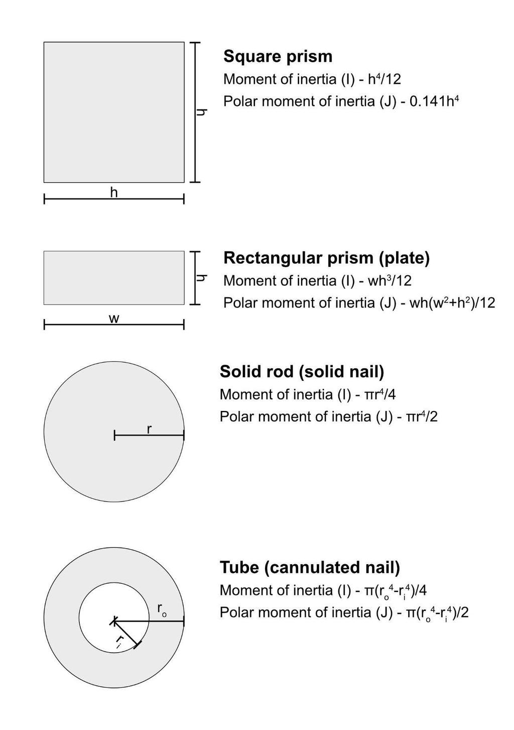
6 performance by changing geometry than by selecting different materials. The moment of inertia of area (I) describes the distribution of material in cross section around a theoretical neutral axis (Figure 2). Bending of an object occurs about this axis, thus when stress is applied to objects with a solid symmetrical cross-section bending occurs about the centre line with tension occurring on the side that is stretched and compression on the other side that becomes shorter. The neutral axis describes the point in the structure that is effectively subjected to zero net force thus material on the bending axis has very little stress applied to it. The presence of a neutral axis means that hollow materials can be more effective at supporting loads than solids, as the material can be concentrated where it is needed. The further the material within the object is located away from the neutral axis generally the greater the stiffness. This is evident in building construction in steel beams with an "I" cross section that have top and bottom plates separated by a thin vertical rib; these beams push material away from the neutral axis to increase the moment of inertial of area. If the direction of bending is known, like in a civil engineering supporting beam, the material within the beam can be specifically positioned, however, in the case of a long bone where forces can act in many planes, often at the same time, the most effective cross section becomes a circular annulus. Figure 2 Different mathematical formulas describe I for objects with different cross sectional shapes, under different types and direction of loading. This is important because, as described above, the material further away from the neutral axis in the plane of deformation will have more effect on rigidity. The equivalent property under torsional loading is known as the polar moment of inertia of area (J). Examples for common cross sections encountered in orthopaedic implants are shown in Figure 3. For objects with complex cross-sectional shapes, the overall moment of inertia of area can be calculated by adding or subtracting the moment of inertia of the simple shapes for the material that is or is not present respectively. A good example is that is of a hollow tube where I or J of the overall cross section is equal to that of the outer diameter circle minus the inner circles diameter (Figure 3). If the bending axes are not coincident in the shapes, it is necessary to use the parallel axis theorem; this is beyond the scope of this paper.(1) Figure 3 The body takes great advantage of material distribution in long bones such as the femur by creating an annular hollow structure under the control W.(2) The value of I (bending) and J (torsion)
7 are a function of the radius to the power of 4, hence for any given cross-sectional area I,J are greatest if the internal material is removed and placed more peripherally (further from the neutral axis). For the case of a solid shaft with the same cross-sectional area as the example in Figure 1 (D solid=19.9 mm) the magnitude of I,J would decrease by a factor of 5 (I anular/i solid =5). Thus, when using the same amount of material, a hollow tube will be more rigid under bending or torsion than a solid rod as the material is placed away from the neutral axis where it has more effect. A long bone is therefore adapted to its function as a tube will be lighter than a solid bone with the same diameter. Similarly increasing the diameter of a rod by a small amount greatly increases its bending rigidity. For example, a 9mm intramedullary nail would be approximately 50% more rigid than an 8mm nail. This effect is seen in ageing osteoporotic bones where the amount of osseous material available is decreased. A W diameter large, creating the most rigid, strong structure possible with the given material. Typical values of bending rigidity for common structural shapes are shown in Table 1; note the cross sectional area (proportional to the mass assuming length is maintained) is constant for all of the objects shown and only the shape has been altered. This is the equivalent of forming different objects using the same amount of material, of the same length, but with different shape. For comparison to the annular cross-section shown in Figure 1, the moment of inertia of area of a rectangular section (as in a plate) is equal to I plate, where w is the width and h is the thickness. Note that, as the moment of inertia of area is proportional to the thickness of the plate to the power three, small increases in plate thickness result in large increases in bending rigidity. Increasing the plate thickness from 2 to 3mm would lead to the bending rigidity increasing approximately 3 fold. Table 1 As the cross-sectional area (mass) of all of the shapes in Table 1 is identical, under an axial load all of the beams would deform the same amount. However, under a bending load their stiffness and thus their ability to resist deformation varies by up to 16 times. These examples also demonstrate that altering geometry has a much more important effect than altering material. For example, the plate on its edge (ii) is 9.6 times more rigid than the same plate on its side (i), whereas changing material would only change the rigidity by 2. The most rigid object in Table 1 is the annular cross-section, it is also the thinnest, demonstrating that the distribution of material in a particular shape is most important. The annular tube (v) has a stiffness 5.5 times greater than a solid rod (iv). This is adopted
8 in modern bicycles that utilise very thin aluminium or carbon tubing that have a very large diameter compared to the smaller diameter, thicker steel tubing used historically. The structure of the long bones varies significantly. The reasons for this can be determined by considering the forces W In the metaphysis, adjacent to the joint, limited bending forces are encountered; friction is low, impact forces can be high and muscle action will tend to move the joint rather than apply a bending force to the bone. Hence, the metaphyseal bone is porous and cancellous. This bone can absorb proximal impacts and transmit the resulting stress along the length to the cortex. The trabeculae are aligned with the direction of load transfer and supported additionally by cross braces much like a step ladder, to prevent the slender trabeculae from buckling. Bending and torsion increases along the length of the bone, therefore, the structure of bone changes to become a dense cortical annulus. Hence, the bone changes naturally to support the load applied to it. Designers can copy this by preferentially reinforcing materials to increase their moment of inertia of area in areas of high stress by varying their thickness and orientation to the bending axis. It must however be remembered that if constructs are excessively rigid they will shield the bone from forces. This can result in poor fracture healing in the short term and resorption of bone with resultant failure in the long term due to localised osteoporosis and bone weakening.(3) This is commonly seen following total hip replacement as the proximal femur is shielded from the complex stresses applied to it by the essentially rigid femoral stem leading to bone loss proximally and bone growth distally.
9 Clinical Examples; Internal fixation plates Internal fixation plates and rods are fastened in place with bone screws of varying type, some providing rigid fixation and others providing a degree of controlled movement. The necessity for screws requires the plate/rod to have a range of access holes to accommodate anatomical variation. From an engineering perspective there are general common sense design rules that are useful to consider. Holes, in particular, should be avoided in any construct as they reduce the cross sectional area locally and therefore act as a point of weakness. If required they should be placed where possible more than 1 diameter from an edge of the plate and more than 1 diameter from the next adjacent screw hole. This is because features such as holes, notches, grooves, threads, or any sudden changes in geometry act to provide stress concentrations that accentuate the localised stress to be up to an order of magnitude greater than if the feature was not present.(1) Thus an important aspect to consider in design is to keep stress concentrations away from the location of maximum bending moment where stresses are at their greatest. In internal fixation devices, the absolute application of engineering principles are sometimes disregarded due to practical constraints, particularly for trauma applications. The constructs cannot ordinarily be manufactured for each individual situation and therefore must be versatile enough to be used in different injury patterns in different individuals. A good example of this is the fact that many plates will have holes for screws throughout their length. It may therefore be impossible to avoid having features (such as holes) at the location of maximum bending moment. Some more modern designs try to take this into account, examples are shown in Figure 4 A and B. The operating surgeon must otherwise take account of any short-comings in implant design when faced with a particular situation. This will allow synthesis of constructs which will mitigate these issues, examples are shown in Figure 4 C and D where addition fixation has been added to neutralise particular forces. Figure 4 Where fractures are slow to unite and / or such issues are not taken into account, implant failure can occur. The redundant screw holes in Figure 5 are a prime example of this. Due to their proximity to the fracture site, these holes cannot be used, they therefore represent a point of weakness in the area of maximum bending stress opposite the unstable fracture site, contributing to the ultimate failure of the device. Had the plate not had holes in this particular location it would likely not have failed.
10 Considering the plate construct in Figure 5, as screws on an individual side of the fracture site get closer together, the force applied to them increases as jointly they form a force couple. A force couple is defined as two points of load that together produce a bending moment. The two forces within a force couple have equal magnitude but opposite direction, hence, one is in compression and one in tension.(1) The overall resistance to bending is the magnitude of one force multiplied by the distance between the screws. The bending moment is a function of the load applied to the limb, thus as the screws get closer together on a specific side the force on each screw increases linearly. Furthermore, if the applied moment changes direction, the force in the screws swaps from tension to compression. It is important to note that screw holes provide stress concentrations to the bone and therefore, screws should not be placed too close to the edge of a bone/fracture. It is also crucial that there are at least 2 screws on each side of the fracture site as an individual screw, whilst being able to resist shear, will not resist a bending moment applied to the plate. By convention at least 3 or 4 bicortical screws are applied dependent on the anatomic location to improve pull out strength of the plate. An additional consideration is the stability/movement at the fracture site. The working length of the plate is defined as the distance between the nearest screws on each side of the fracture. Screws further from the fracture site (greater working length) allow greater bending to occur within the plate and thus provide greater movement/instability. Increased working length also places more stress on the plate as the plate deforms and a greater pull-out force on the nearest screws. It should be noted that this only applies when there is bending or torsional loading as under a purely axial load the screws would be in shear and the working length would be less important. Figure 5 Conventional plates obtain fixation by compressing the plate against the bone as the screw gains purchase, thus stability is achieved by friction of the plate against the bone. (Figure 6 A and B) For this to occur the bone must be of sufficient quality for screw purchase to provide this compression, this can be problematic in osteoporotic patients. Screws can toggle in the hole in the plate and pull out along the line of least resistance. Each screw plate interface acts as an independent point of fixation and can move and therefore fail independently. This means that the screw subjected to the greatest force can fail first, resulting in the subsequent screws being subjected to increasing force and failing sequentially. These plates frequently fail by screw cut out in this mode. Newer generations of plating systems include locking plates. These systems obtain fixation by a completely different mechanism (see Figure 6 C and D). The screws have a thread on their head with a corresponding thread in the
11 plate hole, therefore after insertion the screw head locks into the plate. This affords angular stability to each screw and in effect the construct will act as a single structure once completed. This has several important implications for construct mechanics. Locking plate systems obtain stability by 3-point fixation via each screw, these being the locking mechanism between the screw and plate, the screw purchase in the near cortex and the screw purchase in the far cortex. Insertion of several screws therefore potentially generates an extremely stable construct in this regard. This also means that the plate can provide stability without being in contact with the bone, acting as an internal fixator. In unstable fractures, angular stability is inherent to the system and this can improve maintenance of reduction and reduce the risk of implant failure. As the screws are fixed into the plate and cannot toggle, it is less likely for screws to fail individually as on angular loading all of the screws will resist cut out. It is therefore less common that these locking plates fracture, however, if the fracture does not unite rapidly enough the plate may experience long term repeated loading and fail by subsequent fatigue failure, as has occurred in Figure 5. Figure 6 Internal fixation nails The mechanics of intramedullary nails in regard to their cross sectional geometry is discussed above. It is important to remember that due to the 4 th power relationship between the radius and the strength and rigidity of the nail, small increases in nail size will have a profound effect on mechanics. An important aspect to consider is also the fit of the nail to the cortical bone support within the medullary canal (Figure 7.). Nails are generally long, with fixation at either end by a cluster of locking bolts. This leads to long moment arms and therefore the potential for large bending forces transferred to this fixation. When loaded in bending, a similar long plate and screw construct would result in very high stress in the screws which would likely fail due to the proximity of the screws to each other and the long moment arm. However, dependent upon the way that the nail has been inserted, the inner geometry of the bone generally provides support and limits the amount the rod may bend thus reducing the bending stress applied to the nail. Therefore, the nails primary function is to support axial and shear loads only. The stress within the screws, however, may be very complex. The mechanics generated will depend upon how close the fit of the nail is to the medullary canal and can be understood in terms of the nails working length. A narrow nail inserted into a large medullary canal will potentially not achieve any contact fit at the isthmus of the long bone. The working length in such a case is between the two set of locking bolts and large force transfers as described above can occur. By reaming the medullary canal, not only can a larger nail be inserted, but as a cylindrical channel is
12 created the fit of the nail will potentially be much closer. If tight fit is achieved either side of the fracture, then the working length is effectively shortened between these points. If there is a close fit between the nail and the bone, the fixation bolts will generally need to resist only simple shear, as designed. However, as the fit gets wider, leading to a gap between the bone and the intermediary nail, the screws act as a cantilever at each end with complex bending taking place. This may lead to fatigue failure over time, as portrayed in Figure 7. Figure 7 When designing or applying any implant for bone stabilisation, it is important to consider the effect of design and technique of application not only on the mechanical environment at the fracture or implantation site but also the forces in the implant itself. As alluded to above, the way that a device is applied may profoundly alter the stresses that it will be subjected to on loading. According to N apply large forces to the implant will also potentially apply large reciprocal forces at the bone implant interface. This may lead to failure at this point. Perhaps the most profound example of this relates to the working length as described above. The same effect is illustrated in Figure 8 in the context of a plate. Here we see that moving fixation close to the focus of instability (fracture) reduces the working length of the implant, this will increase rigidity, reducing motion at the fracture site. This means that the implant must be sufficiently strong to withstand these forces if the implant is to be used in this mode. Fracture site mechanics influence healing and the effect of implant design and method of implantation must be considered taking both the effect on the fracture and the implant into account. This is a more complex situation than might initially be apparent as most constructs have degree of inherent stability imparted by the bone itself dependent on configuration. A well reduced fracture simple fracture with stable fixation will result in a load sharing construct with the majority of the force transfer being between the bone fragments rather than the implant itself. This protects the implant and results in a much lower risk of failure. A poorly reduced fracture or a more complex injury without inherent stability relies entirely on the implant which will act in a load bearing manner. This is described more fully elsewhere.(3) Figure 8 External fixation External fixation systems are in general highly modular, their mechanical performance is therefore dependent on their components alongside the construct that is assembled. Simple mono-lateral
13 fixators utilise pins inserted into the bone connected outside the body by a series of rods and clamps. With regards to construction, perhaps the most important aspect to consider is that of working length. In general, this means having 2 points of fixation wherever possible and maximising moments and lever arms where they are advantageous and reducing them where they might increase force transfer and instability (increasing span over stable segments and reducing span across areas of instability). This leads to the concept of near-far fixation which is covered more fully elsewhere.(4) The structural rigidity will depend upon the material from which they are made and their design. Most external fixator pins are stainless steel. Whilst titanium pins exist, they are less rigid and offer little advantage in other respects for this application. Older systems employ hollow metal connecting rods, with almost all newer rods being made of carbon fibre composite. These are more rigid, lighter and are safe to be placed inside a magnetic resonance imaging scanner should the patient require this. The majority of important components are simple rods, which as described above, will have a bending rigidity proportional to the 4th power of their radius. Therefore, increasing the diameter of bone fixation pin from 4 to 5mm will result in 2.5-fold increase in its rigidity; a 6mm pin is twice as rigid as a 5mm pin. Large 12mm interconnecting bars found in modern fixators are more than 5 times more rigid than older 8mm equivalents. Selecting modern systems with more rigid components allows stabile constructs to be constructed with more simple designs and fewer parts. Multi-planar frames, particularly those utilising fine wires such as the Ilizarov fixator, have more complex mechanics. The function of the pin or tensioned wire is to provide support to the relative bones whilst healing (Figure 9). This demonstrates that transfixation wires will potentially generate a beam-loading mechanical environment when axial loads are applied. Pre-tensioned wire mechanics are complex as the wires are flexible and the tension will additionally increase when the frame is loaded resulting in the wires self-stiffening. This is traditionally understood to generate favourable fracture healing mechanics by permitting a degree of axial motion whilst preventing shear.(3) Uniplanar half pins generate different mechanics by creating a cantilever bending mechanical environment, this leads to different forces at the fracture site and may induce unfavourable shear (Figure 10). Pins and wires are often applied asymmetrically to the limb to minimise soft tissue trauma. This creates a non-linear deformation during gait as the bone is held more rigid relative to a given plane (closer to the edge of the frame). Combinations of pins and wires in different planes lead to complex mechanics and there is the potential for generating shear by cantilever bending creating shear when half pins are included in constructs. However, when utilising these in particular configurations this appears to be at levels unlikely to be of clinical importance.(5)
14 Figure 9 Pins may fatigue at the point of maximum bending moment and maximum stress concentration, both of which exist at the junction with the bone, the stress concentration coming from the presence of threads. Wires are thin (~2mm) and tensioned so experience primarily an axial load similar to a stretched cable uniquely allowing the bone to move relative to the wire; there is also a knurled version of the wire (olive wires) that is textured and designed not to move in the bone. The pin/wire provide support to the bone with the shorter pin or greater tensioned wire providing the most support. The absence of pins on a single side means that there is locally less restriction to movement and the fracture is more likely to toggle about the more rigid side.(5) Figure 10 The frame that supports the pins and wires and hence the fracture, is usually constructed from individual modular components. Each frame is therefore a unique structure with its form depending on the characteristic of the fracture and the patient that restricts assembly. Traditional frame structures are generally far stiffer than the pins and wires and can be considered almost rigid in comparison.(5) The amount of bending or torsion that occurs within the frame is a function of the position of the axial support rods relative to the axes that the bending moment is applied. Hence if the rods are further away from the bending axis (neutral axis) the stiffness of the frame will increase. Straight rods generally provide more resistance to bending than hexapod rods that are positioned at an angle. Under torsional loads however, a hexapod arrangement provides more torsional support than straight rods. This occurs because under bending, straight rods experience greater axial compression/tension and under torsion the straight rods act more like cantilever beams. Thus the more axially the load is applied to an individual component the greater the resistance to deformation of that component (Figure 1). It must be noted that there are many components within an Ilizarov frame so the ultimate support provided is complex. The actual load applied by the patient will produce a combination of axial, bending, and torsion that will be different in the pin/wire, frame and rod and will be furthermore dictated by patient weight and the particular activity they are doing.
15 Conclusion To promote bone healing medical devices are intended to provide a specific level of strain or deformation to the fracture site. An understanding the fundamentals of stress is important in the preoperative planning /selection of these devices to complement the specific support that is intended. Acknowledgements This work was supported by the NIHR (National Institute for Health Research) through funding of the LMBRU (Leeds Musculoskeletal Biomedical Research Unit). Glossary Stiffness a material characteristic expressing deformation under load. Proportional to the gradient for the linear part of the stress-strain curve for that material. Rigidity characteristic of a construct expressing the deformation under loading. Determined by the materials stiffness, the geometry of the construct and the direction and type of load applied. Neutral axis Theoretical axis in a construct that is subjected to zero net force when a load is applied in bending or torsion. Area moment of inertia expresses a structures material distribution in cross section in relation to bending strength and stiffness. Polar moment of inertia expresses a structures material distribution in cross section in relation to torsional strength and stiffness. References 1. Beer FP. Mechanics of materials. 5th ed. New York ; London: McGraw-Hill Higher Education; xix, 782 p. p. 2. Wolff J. The classic: on the inner architecture of bones and its importance for bone growth Clin Orthop Relat Res. 2010;468(4): Harwood PJ, Ferguson DO. (ii) An update on fracture healing and non-union. Orthopaedics and Trauma. 2015;29(4): Taylor D, Tebby J, Foster P, Harwood P. (iii) Temporary skeletal stabilization in major trauma. Orthopaedics and Trauma. 2015;29(6): Henderson DJ, Rushbrook JL, Stewart TD, Harwood PJ. What Are the Biomechanical Effects of Half-pin and Fine-wire Configurations on Fracture Site Movement in Circular Frames? Clin Orthop Relat Res
16 Figure and Table Titles Figure 1 Comparison of Axial, Torsion and Bending for an annular cross section. where,, ; representing the moment of inertia of area and polar moment of inertia respectively. Assuming: L = 0.5m, D i = 30 mm, D o = 36 mm (Cross sectional area A =311 mm 2 ), E = 10 GPa, G = 1 GPa, F = 1000 N, T = 10Nm. Figure 2 Example of the neutral axis under bending load. Note that material further from the neutral axis is subjected to increasing tension on the convex side and increasing compression on the concave side. The material along the neutral axis is subjected to zero net force along the axis. Figure 3 Example formulae for the moment of inertia and polar moment of inertia of commonly encountered orthopaedic implants. Table 1 Bending stiffness (EI in GPa m 4 ) of common object cross-sectional shapes made of steel or titanium (cross sectional area = 311 mm 2 ). E Steel = 200 GPa, E Titanium = 110 GPa. Note: the bending axis is perpendicular to this cross-section with the load applied vertically. Figure 4 Examples of different trauma implants with design features which attempt to mitigate stress concentration in common areas of weakness. Note the lack of features in the areas of maximal bending stress in typical injury. A) Plate for distal radial fracture note that the plate is thickened and there are no holes in the area of the plate where bending loads will frequently be applied in unstable fractures. B) Dynamic compression plate note the scalloping of the plate to reduce stress concentration around features and allow smooth contouring of the implant. C) Intramedullary nail to stabilise a transverse osteotomy which is inherently unstable note that a plate has been added to help neutralise shear and bending forces and reduce loads at the locking bolts. D) An intramedullary hip screw note that the nail is thickened proximally at the area where maximal load is usually applied and to help mitigate for the large hole for the screw in the femoral head. The surgeon has added a circlage wire at the fracture in an attempt to reduce bending forces on the nail and maintain contact. This was ultimately unsuccessful (inset) and the nail underwent fatigue failure at the large hole proximally. Figure 5 Clinical example of a fractured plate and basic schematic of plate / screw configuration with resultant stresses. Note that the plates have both undergone failure at screw holes which corresponds to points of stress concentration at the fracture site. Figure 6 Comparison of fixation method for non-locked and locked plating systems. A each screw exerts a compressive force on the plate, maintaining stability by friction of the plate against the bone. B Forces are applied to each screw and as these move they fail sequentially resulting in cut out. C Locked plates have screws which lock into the plate itself these obtain multiple point fixation and form an extremely rigid construct in the intact bone segment (red boxes). D this transfers force to the plate and therefore these systems will tend to fail by implant fracture rather than screw pull out. Figure 7 - Schematic of femoral nail fit and clinical fracture. With close fit screws experience shear only, whereas a wide fit leads to cantilever bending.
17 Figure 8 Working length of a plate illustrating the effect of moving fixation relative to the fracture site. A Fixation near and far to the fracture site increases working length, reducing fracture site motion and increasing stress concentration in the plate. B Moving fixation away from the fracture site increases working length, increasing fracture site motion and reducing stress concentration in the plate. Figure 9 - Example of Hexapod (A) and Ilizarov frames (B) with pins and tensioned wires. Figure 10 Mechanics of ring and mono-lateral external fixators. A - ring fixator with tensioned fine wires. On loading the wires are tensioned further and beam loading is generated. This results in controlled axial motion at the fracture site. B mono-lateral fixator with rigid half pins. On loading a torsional force is generated and cantilever bending occurs. This results in shear at the fracture site.
18 Table 1 Bending stiffness (EI in GPa.m 4 ) of common object cross-sectional shapes made of steel or titanium (cross sectional area = 311 mm 2 ). E Steel = 200 GPa, E Titanium = 110 GPa. Note: the bending axis is perpendicular to this cross-section with the load applied vertically. i Beam Cross-section I, moment of inertia of area mm 4 31mm wide I = 31 x 10 3 /12 rectangular plate 10mm thick mm 4 EI steel EI titanium GPa.m 4 GPa.m Ii 10mm wide rectangular plate 31mm thick I = 10 x 31 3 / mm x i 2730 Iii iv v Two stacked rectangular plates (31 mm wide x 5 mm thick) separated by 10mm I = [I outside - I inside] 19.9 mm diameter Solid rod. 36 mm diameter hollow tube, 3.0mm thick (Figure 1). I = [(31x20 3 /12) - 31x10 3 /12] mm mm mm x i x i x i 5.5 x iv
19

20

21

22


23

24
25


26

27
Biomechanics of Fractures and Fixation
 Biomechanics of Fractures and Fixation Theodore Toan Le, MD Original Author: Gary E. Benedetti, MD; March 2004 New Author: Theodore Toan Le, MD; Revised October 09 Basic Biomechanics Material Properties
Fracture fixation. Types. Mechanical considerations. Biomechanics of fracture fixation. External fixation. Internal fixation
 Fracture fixation Biomechanics of fracture fixation Types External fixation Mechanical considerations Internal fixation Mechanical considerations in treatment of 1. In the external fixation: fracture When
EXTERNAL FIXATION SYSTEM
 EXTERNAL FIXATION SYSTEM The Apex Pin Fixation System is a one step procedure reducing insertion time and reducing insertion temperature. There are three types of fixation pins: Self-drilling / Self-tapping
Types of Plates 1. New Dynamic Compression Plate: Diaphyseal fracture: Radius, Ulna, Humerus, Rarely tibia
 Types of Plates 1. New Dynamic Compression Plate: DCP Diaphyseal fracture: Radius, Ulna, Humerus, Rarely tibia 1. Undercut adjacent to the holes low contact: less stress shield 2. Undercut at the undersurface
LOCKING TEP LOCKING TITANIUM ELASTIC PIN INTRAMEDULLARY NAIL
 LOCKING TEP LOCKING TITANIUM ELASTIC PIN INTRAMEDULLARY NAIL ... Index -3 3-8 8 9 9 0 7 Introduction Features Indicatiıons Surgical Technique Femoral Surgical Technique Tibial Surgical Technique Ulna Radius
External Skeletal Fixation (ESF)
") External Skeletal Fixation (ESF) Technique for fracture repair in animals Introduction External Skeletal Fixation is a versatile and effective technique for fracture repair in animals, rigidly stabilizing
External Skeletal Fixation (ESF) Technique for fracture repair in animals Introduction External Skeletal Fixation is a versatile and effective technique for fracture repair in animals, rigidly stabilizing
Elbow Hinge Fixator. Guided Flexion/Extension for Unstable Elbow Fractures.
 Elbow Hinge Fixator. Guided Flexion/Extension for Unstable Elbow Fractures. Surgical Technique MR Safe Radiolucent Table of Contents System Description 3 Indications and Contraindications 4 Fixation Components
QUICK REFERENCE GUIDE. The PreFix Fixator (92000 Series) ALWAYS INNOVATING
 ALWAYS INNOVATING") 21 The PreFix Fixator (92000 Series) ALWAYS INNOVATING INTRODUCTION The PreFix fixator is designed to provide temporary external fixation. This may be needed when local facilities or the condition of the
21 The PreFix Fixator (92000 Series) ALWAYS INNOVATING INTRODUCTION The PreFix fixator is designed to provide temporary external fixation. This may be needed when local facilities or the condition of the
Monolateral External Fixation System for Trauma and Orthopaedics
 MEFiSTO Monolateral External Fixation System for Trauma and Orthopaedics Surgical Technique Original Instruments and Implants of the Association for the Study of Internal Fixation AO/ASIF MEFiSTO Table
Comparative Study of Fixation Devices for Intertrochanteric Fractures
 Comparative Study of Fixation Devices for Intertrochanteric Fractures C. Sticlaru * A. Davidescu Politehnica University of Timişoara Politehnica University of Timişoara Timişoara, România Timişoara, România
LCP Medial Distal Tibia Plate, without Tab. The Low Profile Anatomic Fixation System with Angular Stability and Optimal Screw Orientation.
 LCP Medial Distal Tibia Plate, without Tab. The Low Profile Anatomic Fixation System with Angular Stability and Optimal Screw Orientation. Technique Guide LCP Small Fragment System Table of Contents Introduction
Small Fragment Plating System
 Small Fragment Plating System Securing optimal fixation through locked and compression plating technology SURGICAL TECHNIQUE RECOVERY FUNCTION SURVIVORSHIP DePuy believes in an approach to trauma surgery
Muscle-Tendon Mechanics Dr. Ted Milner (KIN 416)
") Muscle-Tendon Mechanics Dr. Ted Milner (KIN 416) Muscle Fiber Geometry Muscle fibers are linked together by collagenous connective tissue. Endomysium surrounds individual fibers, perimysium collects bundles
Muscle-Tendon Mechanics Dr. Ted Milner (KIN 416) Muscle Fiber Geometry Muscle fibers are linked together by collagenous connective tissue. Endomysium surrounds individual fibers, perimysium collects bundles
Designing a Novel Fixation Device for Pediatric Orthopaedic Tibia Fractures
 Designing a Novel Fixation Device for Pediatric Orthopaedic Tibia Fractures Evan Lange, Karl Kabarowski Tyler Max, Sarah Dicker Client: Dr. Matthew Halanski, MD Advisor: Dr. Paul Thompson, PhD Biomedical
RibFix Blu. Thoracic Fixation System
 RibFix Blu RibFix Blu Thoracic Fixation System The New Era of Rib Fixation Begins Now Designed by Trauma Surgeons for Trauma Surgeons Your work matters and so do your patients. We are continually engineering
AcUMEDr. Anatomic Midshaft Forearm Plates
 AcUMEDr Anatomic Midshaft Forearm Plates Anatomic Midshaft Forearm Plates Since 1988, Acumed has been designing solutions to the demanding situations facing orthopaedic surgeons, hospitals and their patients.
Introduction to the Taylor Spatial Frame Hardware. Trademark of Smith & Nephew. Certain marks Reg. US Pat. & TM Off.
 Introduction to the Taylor Spatial Frame Hardware Trademark of Smith & Nephew. Certain marks Reg. US Pat. & TM Off. What is the Taylor Spatial Frame? Next generation circular fixator capable of 6 axes
PediLoc 3.5mm and 4.5mm Contour Femur Plate Surgical Technique
 PediLoc 3.5mm and 4.5mm Contour Femur Plate Surgical Technique Surgical Technique Contour Femur Plate The technique description herein is made available to the healthcare professional to illustrate the
Case Report. Antegrade Femur Lengthening with the PRECICE Limb Lengthening Technology
 Case Report Antegrade Femur Lengthening with the PRECICE Limb Lengthening Technology S. Robert Rozbruch, MD Hospital for Special Surgery New York, NY, USA ABSTRACT This is a case illustrating a 4.5 cm
Zimmer Small Fragment Universal Locking System. Surgical Technique
 Zimmer Small Fragment Universal Locking System Surgical Technique Zimmer Small Fragment Universal Locking System 1 Zimmer Small Fragment Universal Locking System Surgical Technique Table of Contents Introduction
Technique Guide. The Distraction Osteogenesis Ring System. Nonarticular tibia frame.
 Technique Guide The Distraction Osteogenesis Ring System. Nonarticular tibia frame. Table of Contents Introduction The Distraction Osteogenesis Ring System 2 AO Principles 4 Indications 5 Surgical Technique
Small External Fixator Nonspanning Wrist Frame. For the treatment of wrist fractures.
 Small External Fixator Nonspanning Wrist Frame. For the treatment of wrist fractures. Technique Guide Part of the Small External Fixation System Small External Fixator Nonspanning Wrist Frame When to use
Knee spanning solutions
 Knee spanning solutions System features Indications Intended to be used on adults or pediatric patients as required for fracture fixation (open or closed); post-traumatic joint contracture which has resulted
Technique Guide Small Bone Fusion System
 Technique Guide Small Bone Fusion System The Pinit Plate Small Bone Fusion System is a super low profile, modular bone plate and screw system designed to stabilize a bunionectomy with a medial to lateral
PLR. Proximal Loading Revision Hip System
 PLR Proximal Loading Revision Hip System The PLR splined revision stem is designed to recreate the natural stresses in the revised femur, where proximal bone may be compromised. PLR Hip System Design Considerations
AcUMEDr. Olecranon Threaded Compression Rod
 AcUMEDr Olecranon Threaded Compression Rod Olecranon Threaded Compression Rod Since 1988, Acumed has been designing solutions to the demanding situations facing orthopaedic surgeons, hospitals and their
MEFiSTO. Monolateral External Fixation System for Trauma and Orthopaedics.
 MEFiSTO. Monolateral External Fixation System for Trauma and Orthopaedics. Surgical Technique This publication is not intended for distribution in the USA. Instruments and implants approved by the AO Foundation.
Pre-Operative Planning. Positioning of the Patient
 Surgical Technique Pre-Operative Planning Decide upon the size and angle of the barrel plate to be used from measuring the x-rays. To maximise the sliding action when using shorter lag screws, the Short
3.5 mm Locking Attachment Plate
 For Treatment of Periprosthetic Fractures 3.5 mm Locking Attachment Plate Surgical Technique Table of Contents Introduction 3.5 mm Locking Attachment Plate 2 Indications 4 Surgical Technique Preparation
WINSTA-C. Clavicle Plating System
 Clavicle Plating System Clinical Advisor Michael Kurer FRCS FRCS (Orth) Consultant Orthopaedic and Shoulder Surgeon North Middlesex University Hospital NHS Trust Table of Contents Introduction Indication
Conventus CAGE PH Surgical Techniques
 Conventus CAGE PH Surgical Techniques Conventus Orthopaedics The Conventus CAGE PH (PH Cage) is a permanent implant comprised of an expandable scaffold, made from nitinol and titanium, which is deployed
Principles of intramedullary nailing. Management for ORP
 Principles of intramedullary nailing Eakachit Sikarinklul,MD Basic Principles of Fracture Management for ORP Bangkok Medical Center Bangkok, 22-24 July 2016 Learning outcomes At the end of this lecture
Small Fragment Plating System. Securing optimal fixation through locked and compression plating technology
 Small Fragment Plating System Securing optimal fixation through locked and compression plating technology Contents Design Rationale Introduction Interfragmentary Fixation Insertion of a 3.5 mm Cortical
Surgical Technique. Cannulated Angled Blade Plate 3.5 and 4.5, 90
 Surgical Technique Cannulated Angled Blade Plate 3.5 and 4.5, 90 Cannulated Angled Blade Plate 3.5 and 4.5, 90 Table of contents Indications/Contraindications 2 Implants 3 Surgical technique 5 Implant
Improving Fixation of a Previously Designed Pediatric Tibial Stent
 Improving Fixation of a Previously Designed Pediatric Tibial Stent Evan Lange, Karl Kabarowski, Tyler Max, Sarah Dicker, Lida Acuña-Huete Client: Dr. Matthew Halanski, MD Advisor: Dr. Wan-Ju Li, PhD Biomedical
Intelligent Orthopaedics
 Intelligent Orthopaedics Nailing Stand Instructions for Use and Guidance doc - iostorm-04-1.1 Contents Instructions for use 2 Description 3 Caution 3 Preparation 4 Pre-setting height 4 Proximal Wire Insertion
operative technique Kent Hip
 operative technique Kent Hip The Kent Hip Operative Technique The Kent Hip was developed by Mr Cliff Stossel, FRCS in Maidstone, Kent, UK and first implanted in 1986. It was designed to deal with problems
Extron External Fixator
 Operative Technique Extron External Fixator The disposable set for a Distal Radius Fracture The EXTRON-External Fixator made by tantum provides you with a new generation of supply engineering for distal
PediLoc 3.5mm and 4.5mm Bowed Femur Plate Surgical Technique
 PediLoc 3.5mm and 4.5mm Bowed Femur Plate Surgical Technique 2957 Bow Broch_REV_B.indd 1 2/10/11 12:47 PM Surgical Technique Bowed Femur Plate The technique description herein is made available to the
Comparitive Study between Proximal Femoral Nailing and Dynamic Hip Screw in Intertrochanteric Fracture of Femur *
 Open Journal of Orthopedics, 2013, 3, 291-295 Published Online November 2013 (http://www.scirp.org/journal/ojo) http://dx.doi.org/10.4236/ojo.2013.37053 291 Comparitive Study between Proximal Femoral Nailing
External Distal Radius Fixator. Supplement to the 8 mm rod fixator system
 External Distal Radius Fixator. Supplement to the 8 mm rod fixator system Surgical technique This publication is not intended for distribution in the USA. Instruments and implants approved by the AO Foundation
TIPMED EXTERNAL FIXATION SYSTEMS
 TIPMED EXTERNAL FIXATION SYSTEMS ANATOMICAL LOCATIONS FOR EXTERNAL FIXATION SYSTEMS Humeral Dynamic Axial Fixator Elbow Fixator Pelvic Dynamic Axial Fixator Pennig Wrist Fixator Hand Fixator Finger Fixator
EXTENDED TROCHANTERIC OSTEOTOMY SURGICAL TECHNIQUE FPO EXTENSIVELY COATED FIXATION
 EXTENDED TROCHANTERIC OSTEOTOMY SURGICAL TECHNIQUE FPO EXTENSIVELY COATED FIXATION SINCE 1983 PREOPERATIVE PLANNING EXPLANTATION OPTIONS the cement from inside the cement canal until the bone/ cement bond
Patient Guide. Intramedullary Skeletal Kinetic Distractor For Tibial and Femoral Lengthening
 Patient Guide Intramedullary Skeletal Kinetic Distractor For Tibial and Femoral Lengthening Introduction You have decided to have a limb lengthening operation. The surgery you have chosen uses a device
Technique Guide. Compact 2.0 LOCK Mandible. The locking system for the mandible.
 Technique Guide Compact 2.0 LOCK Mandible. The locking system for the mandible. Table of Contents Introduction Compact 2.0 LOCK Mandible 2 AO Principles 4 Indications and Contraindications 5 Surgical
Clinical Evaluation Surgical Technique
 Clinical Evaluation Surgical Technique Table of Contents EMPERION Specifications 3 EMPERION Surgical Technique 9 EMPERION Catalog 18 Nota Bene: This technique description herein is made available to the
RECLAIM REVISION HIP SYSTEM
 RECLAIM REVISION HIP SYSTEM Where Strength and Modularity Connect DESIGN RATIONALE System Overview RECLAIM Modular Revision Hip System WHERE STRENGTH & MODULARITY CONNECT 2 Offset Options Proximal Body
Locked plating constructs are creating a challenge for surgeons.
 Locked plating constructs are creating a challenge for surgeons. Three recent studies examining supracondylar femur fractures show concern for the high degree of stiffness of locked plating constructs
Mandible External Fixator II. Provides treatment for fractures of the maxillofacial area.
 Mandible External Fixator II. Provides treatment for fractures of the maxillofacial area. Technique Guide This publication is not intended for distribution in the USA. Instruments and implants approved
NEW INSTRUMENTS FOR INTERNAL FIXATION OF FRACTURES USING MINIMALLY INVASIVE TECHNIQUES
 NEW INSTRUMENTS FOR INTERNAL FIXATION OF FRACTURES USING MINIMALLY INVASIVE TECHNIQUES Dr.eng. Comşa Stanca, sing. Gheorghiu Doina, eng. Ciobota Dan National Institute of Research & Development for fine
Technique Guide. DCP and LC-DCP Systems. Dynamic Compression Plates (DCP) and Dynamic Compression Plates with Limited Bone Contact (LC-DCP).
 and Dynamic Compression Plates with Limited Bone Contact (LC-DCP).") Technique Guide DCP and LC-DCP Systems. Dynamic Compression Plates (DCP) and Dynamic Compression Plates with Limited Bone Contact (LC-DCP). Table of Contents Introduction DCP and LC-DCP Systems 2 Indications
Technique Guide DCP and LC-DCP Systems. Dynamic Compression Plates (DCP) and Dynamic Compression Plates with Limited Bone Contact (LC-DCP). Table of Contents Introduction DCP and LC-DCP Systems 2 Indications
Femur Condylar Plate System Procedural Steps.
 Femur Condylar Plate System Procedural Steps www.carbo-fix.com 1 Table of Contents Introduction..3 Instrumentation Set... 8 Procedural Steps:...... 12 Ordering Information 19 2 Introduction The CarboFix
Technique Guide. SureLock Distal Targeting Device. C-arm guided targeting for trochanteric fixation nail.
 Technique Guide SureLock Distal Targeting Device. C-arm guided targeting for trochanteric fixation nail. Table of Contents Introduction SureLock Distal Targeting Device 2 Surgical Technique Preoperative
QUICK REFERENCE GUIDE. The XCaliber Meta-Diaphyseal Fixator
 17 The XCaliber Meta-Diaphyseal Fixator GENERAL POINTS The XCaliber Fixator is made of radiolucent material for unobstructed X-ray visualization. The metallic bolts and the cam and bush of each ball-joint,
Bone Preservation Stem
 TRI-LOCK Bone Preservation Stem Featuring GRIPTION Coating Surgical Technique Implant Geometry Extending the TRI-LOCK Stem heritage The original TRI-LOCK Stem was introduced in 1981. This implant was
Theoretical and Finite Element Modeling of Fine Kirschner Wires in Ilizarov External Fixator
 Theoretical and Finite Element Modeling of Fine Kirschner Wires in Ilizarov External Fixator A. R. Zamani S. O. Oyadiji School of Mechanical, Aerospace and Civil Engineering, University of Manchester,
Orthopedic Bone Nail System - Distal Femoral Nail Surgical Technique Manual
 Orthopedic Bone Nail System - Distal Femoral Nail Surgical Technique Manual Note: The surgical procedures should be performed under the guidance of qualified skilled orthopedic surgeons, and this surgical
Optimum implant geometry
 Design Rationale Optimum implant geometry Extending proven Tri-Lock heritage The original Tri-Lock was introduced in 1981. This implant was the first proximally coated tapered-wedge hip stem available
Technique Guide. 3.5 mm LCP Low Bend Medial Distal Tibia Plates. Part of the Synthes locking compression plate (LCP) system.
 system.") Technique Guide 3.5 mm LCP Low Bend Medial Distal Tibia Plates. Part of the Synthes locking compression plate (LCP) system. Table of Contents Introduction 3.5 mm LCP Low Bend Medial Distal Tibia Plates
Technique Guide 3.5 mm LCP Low Bend Medial Distal Tibia Plates. Part of the Synthes locking compression plate (LCP) system. Table of Contents Introduction 3.5 mm LCP Low Bend Medial Distal Tibia Plates
Pinit Plate Small Bone Fusion System Bone Plate & Screw System
 Pinit Plate Small Bone Fusion System Bone Plate & Screw System Description The Pinit Plate Small Bone Fusion System consists of 2-hole bone plates made available in three length options and two thickness
Technique Guide. 3.5 mm LCP Olecranon Plates. Part of the Synthes locking compression plate (LCP) system.
 system.") Technique Guide 3.5 mm LCP Olecranon Plates. Part of the Synthes locking compression plate (LCP) system. Table of Contents Introduction 3.5 mm LCP Olecranon Plates 2 AO Principles 3 Indications 3 Clinical
Technique Guide 3.5 mm LCP Olecranon Plates. Part of the Synthes locking compression plate (LCP) system. Table of Contents Introduction 3.5 mm LCP Olecranon Plates 2 AO Principles 3 Indications 3 Clinical
Nailing Stability during Tibia Fracture Early Healing Process: A Biomechanical Study
 Nailing Stability during Tibia Fracture Early Healing Process: A Biomechanical Study Natacha Rosa, Fernão D. Magalhães, Ricardo Simões and António Torres Marques Enhanced Bone Healing in intramedullary
For the Attention of the Operating Surgeon: IMPORTANT INFORMATION ON THE MATRIXRIB FIXATION SYSTEM
 For the Attention of the Operating Surgeon: IMPORTANT INFORMATION ON THE MATRIXRIB FIXATION SYSTEM 10/16 GP2685-E-CAN DESCRIPTION The MatrixRIB Fixation System consists of locking plates, locking screws,
EXTERNAL FIXATION SYSTEM
 EXTERNAL FIXATION SYSTEM 2 3 1 4 5 1. DJD II Body 2. Humeral Guide 3. Pin Insertion Guides 4. Hoffmann II Compact Instruments 5. Hoffmann II Compact Components and Apex Pins 2 Overview The DJD II is a
As edited by Dr. Oheneba Boachie-Adjei, Dr. Matthew Cunningham, Dr. John Kostuik, Dr. Raymund Woo and the Complex Spine Study Group et al
 As edited by Dr. Oheneba Boachie-Adjei, Dr. Matthew Cunningham, Dr. John Kostuik, Dr. Raymund Woo and the Complex Spine Study Group et al RANGE Spinal System A fusion of DENALI and MESA, offering a complete
LCP Low Bend Medial Distal Tibia Plates 3.5 mm. Anatomic plates with low profile head for intra- and extraarticular fractures.
 LCP Low Bend Medial Distal Tibia Plates 3.5 mm. Anatomic plates with low profile head for intra- and extraarticular fractures. Surgical Technique This publication is not intended for distribution in the
GAMMA LOCKING NAIL INSTRUMENTS OPERATIVE TECHNIQUE
 GAMMA LOCKING NAIL INSTRUMENTS OPERATIVE TECHNIQUE FEATURES AND BENEFITS The One Shot Device is a new component of the Gamma Locking Nail instrumentation system determining the correct position of the
Encina Taper Stem. Stinson Orthopedics Inc. 303 Twin Dolphin Drive, Suite 600 Redwood City, CA
 Stinson Orthopedics Inc. 303 Twin Dolphin Drive, Suite 600 Redwood City, CA 94065 info@stinsonortho.com www.stinsonortho.com Table of Contents Introduction 3 Features 4 Surgical Technique 5 Preoperative
Intramedullary Nailing: History & Rationale
 Intramedullary Nailing: History & Rationale Overview 1. What is IM Nailing? 2. History 3. Design Rationale & Evolution 4. Modern IM Nails 5. The Future What is IM Nailing? Method of internal fixation in
Humerus shaft - Reduction & Fixation - Compression plate - AO Surgery Reference. Compression plating
 Humerus shaft 12-A3 ORIF 1. Principles Compression plating Authors Compression plate Compression plating provides fixation with absolute stability for two-part fracture patterns, where the bone fragments
.org. Tibia (Shinbone) Shaft Fractures. Anatomy. Types of Tibial Shaft Fractures
 Shaft Fractures. Anatomy. Types of Tibial Shaft Fractures") Tibia (Shinbone) Shaft Fractures Page ( 1 ) The tibia, or shinbone, is the most common fractured long bone in your body. The long bones include the femur, humerus, tibia, and fibula. A tibial shaft fracture
Tibia (Shinbone) Shaft Fractures Page ( 1 ) The tibia, or shinbone, is the most common fractured long bone in your body. The long bones include the femur, humerus, tibia, and fibula. A tibial shaft fracture
*smith&nephew SL-PLUS Cementless Femoral Hip System. Product Information
 Product Information *smith&nephew SL-PLUS Cementless Femoral Hip System First Came the Philosophy to develop a universal hip system that could be used in almost every indication, immaterial to the patient
DuaFit. Proximal Interphal angeal Impl ant
 DuaFit Proximal Interphal angeal Impl ant DUAFIT - TABLE OF CONTENTS PRODUCT DESCRIPTION 3 INDICATIONS 6 SURGICAL TECHNIQUE #1 7 Without guide wire (DuaFit 0 10 17 ) SURGICAL TECHNIQUE #2 14 With guide
Optimum implant geometry
 Design Rationale Optimum implant geometry Extending the proven Tri-Lock heritage The original Tri-Lock was introduced in 1981. This implant was the first proximally coated tapered-wedge hip stem available
28 Surgical Technique
 Surgical Technique 10 12 14 16 18 20 22 24 28 26 Technique described by James L. Guyton, MD Campbell Clinic Memphis, Tennessee James W. Harkess, MD Campbell Clinic Memphis, Tennessee David G. LaVelle,
Technique Guide. LCP Proximal Femoral Hook Plate 4.5/5.0. Part of the LCP Periarticular Plating System.
 Technique Guide LCP Proximal Femoral Hook Plate 4.5/5.0. Part of the LCP Periarticular Plating System. Table of Contents Introduction Features and Benefits 2 AO ASIF Principles 4 Indications 5 Surgical
Technique Guide. DHS Blade. For osteoporotic bone.
 Technique Guide DHS Blade. For osteoporotic bone. Table of Contents Introduction Features and Benefits 2 Indications and Contraindications 4 Clinical Cases 5 Surgical Technique Implantation 6 Implant
Technique Guide. 3.5 mm LCP Low Bend Medial Distal Tibia Plate Aiming Instruments. Part of the 3.5 mm LCP Percutaneous Instrument System.
 Technique Guide 3.5 mm LCP Low Bend Medial Distal Tibia Plate Aiming Instruments. Part of the 3.5 mm LCP Percutaneous Instrument System. Table of Contents Introduction 3.5 mm LCP Low Bend Medial Distal
Provision of Rotational Stability: Prevention of Collapse: Closed Fracture Reduction: Minimally Invasive Surgery with no Exposure of the Fracture:
 INTRODUCTION Percutaneous Compression Plating was developed by considering each of the stages in the surgical procedure for pertrochanteric fractures and the ways in which these might be improved. Primary
MEFiSTO. Monolateral External Fixation System for Trauma and Orthopaedics.
 MEFiSTO. Monolateral External Fixation System for Trauma and Orthopaedics. Surgical Technique This publication is not intended for distribution in the USA. Instruments and implants approved by the AO Foundation.
Fractures (Broken Bones)
") Fractures (Broken Bones) A fracture is a broken bone. A bone may be completely fractured or partially fractured in any number of ways (crosswise, lengthwise, in multiple pieces). Types of Fractures Bones
Fractures (Broken Bones) A fracture is a broken bone. A bone may be completely fractured or partially fractured in any number of ways (crosswise, lengthwise, in multiple pieces). Types of Fractures Bones
Surgical Technique. CONQUEST FN Femoral Neck Fracture System
 Surgical Technique CONQUEST FN Femoral Neck Fracture System Table of Contents Introduction... 3 Indications... 3 Product Overview... 4 Surgical Technique... 5 Patient Positioning... 5 Reduce the Fracture...
Technique Guide. Locking Attachment Plate. For treatment of periprosthetic fractures.
 Technique Guide Locking Attachment Plate. For treatment of periprosthetic fractures. Table of Contents Introduction Locking Attachment Plate 2 Indications 4 Surgical Technique Patient Positioning 5 Preparation
Relationship between the Apex of Flexible Nail and the Level of Fracture: A Biomechanical Study Ahmed N* 1, Gakhar H 2, Cheung G 3, Sharma A 4
 Relationship between the Apex of Flexible Nail and the Level of Fracture: A Biomechanical Study Ahmed N* 1, Gakhar H 2, Cheung G 3, Sharma A 4 Abstract Background Centre of Orthopaedic biomechanics, Bath
LISS DF and LISS PLT. Less Invasive Stabilization Systems for Distal Femur and Proximal Lateral Tibia.
 LISS DF and LISS PLT. Less Invasive Stabilization Systems for Distal Femur and Proximal Lateral Tibia. LISS DF and LISS PLT. Less Invasive Stabilization Systems for Distal Femur and Proximal Lateral Tibia.
Cannulated Angled Blade Plate 3.5 and 4.5, 90.
 Cannulated Angled Blade Plate 3.5 and 4.5, 90. Technique Guide This publication is not intended for distribution in the USA. Instruments and implants approved by the AO Foundation. Table of Contents Introduction
Technique Guide. 2.4 mm Variable Angle LCP Distal Radius System. For fragment-specific fracture fixation with variable angle locking technology.
 Technique Guide 2.4 mm Variable Angle LCP Distal Radius System. For fragment-specific fracture fixation with variable angle locking technology. Table of Contents Introduction 2.4 mm Variable Angle LCP
A Locking IM Rod that won't back out. Simple and straight to the point! SURGICAL TECHNIQUE
 A Locking IM Rod that won't back out. Simple and straight to the point! SURGICAL TECHNIQUE The SLIM (Simple Locking IntraMedullary) System is a new generation of pediatric orthopedic nails specifically
Flexible Fragment Fixation. Surgical Technique
 Flexible Fragment Fixation Surgical Technique 2 F 3 Flexible Fragment Fixation The F 3 Fragment Plating System offers low profile, yet strong fixation in a locked plating construct that can be contoured
Long Volar Plates for Diaphyseal-Metaphyseal Radius Fractures LCP. Dia-Meta Volar Distal Radius Plates. Surgical Technique
 Long Volar Plates for Diaphyseal-Metaphyseal Radius Fractures LCP Dia-Meta Volar Distal Radius Plates Surgical Technique Table of Contents Introduction LCP Dia-Meta Volar Distal Radius Plates 2 AO Principles
Hoffmann II External Fixation System
 Hoffmann II External Fixation System Modular System for Long Bones Pelvis Introduction In 1938, Raoul Hoffmann, a surgeon from Geneva, Switzerland, designed a revolutionary External Fixation System. The
OBSOLETED. LCP Medial Distal Tibia Plate, without Tab. The Low Profile Anatomic Fixation System with Angular Stability and Optimal Screw Orientation.
 LCP Medial Distal Tibia Plate, without Tab. The Low Profile Anatomic Fixation System with Angular Stability and Optimal Screw Orientation. Surgical Technique LCP Small Fragment System This publication
Technique Guide. VA-Locking Intercarpal Fusion System. Variable angle locking technology for mediocarpal partial arthrodesis.
 Technique Guide VA-Locking Intercarpal Fusion System. Variable angle locking technology for mediocarpal partial arthrodesis. Table of Contents Introduction VA-Locking Intercarpal Fusion System 2 Indications
Arcos Interlocking Distal Stem. Surgical Technique Addendum to the Arcos Modular Femoral Revision System
 Arcos Interlocking Distal Stem Surgical Technique Addendum to the Arcos Modular Femoral Revision System One Surgeon. One Patient. Over 1 million times per year, Biomet helps one surgeon provide personalized
ADDRESSING CLINICAL ISSUES OF CEMENTLESS HIP ARTHROPLASTY
 E C H E L O N P R I M A R Y H I P S Y S T E M P R O D U C T R A T I O N A L E ADDRESSING CLINICAL ISSUES OF CEMENTLESS HIP ARTHROPLASTY Echelon Primary Total Hip System HIGH OFFSET STANDARD OFFSET Cementless
BIOMECHANICAL EVALUATION OF INCOMPLETE RINGS AND HYBRID FIXATOR CONSTRUCTS
 BIOMECHANICAL EVALUATION OF INCOMPLETE RINGS AND HYBRID FIXATOR CONSTRUCTS By CALEB C. HUDSON A THESIS PRESENTED TO THE GRADUATE SCHOOL OF THE UNIVERSITY OF FLORIDA IN PARTIAL FULFILLMENT OF THE REQUIREMENTS
3. PATIENT POSITIONING & FRACTURE REDUCTION 3 8. DISTAL GUIDED LOCKING FOR PROXIMAL NAIL PROXIMAL LOCKING FOR LONG NAIL 13
 Contents IMPLANT FEATURES 2 1. INDICATIONS 3 2. PRE-OPERATIVE PLANNING 3 3. PATIENT POSITIONING & FRACTURE REDUCTION 3 4. INCISION 4 5. ENTRY POINT 4-6 6. PROXIMAL NAIL INSERTION 6-7 7. PROXIMAL LOCKING
humerus InSafeLOCK Nail
 humerus InSafeLOCK Nail Introduction Content Humerus InSafeLOCK Nail is an innovative intramedullary nailing system, developed for humerus problems. Humerus fractures have 5-6 % incidence of all bone fractures.
Finite Element Analysis of Radius and Ulna. Eli Pavlatos April 24, 2013
 Finite Element Analysis of Radius and Ulna Eli Pavlatos April 24, 2013 Outline Review bone biomechanics bone behavior during fracture Stress analysis concepts properties of bone for models Fracture simulations
Distal Radius Plate Instrument and Implant Set. Discontinued December 2017 DSUS/TRM/0916/1063(1)
") Distal Radius Plate Instrument and Implant Set Surgical Technique Discontinued December 2017 DSUS/TRM/0916/1063(1) The Distal Radius Plates Indications For fixation of fractures and osteotomies, including
Distal Radius Plate Instrument and Implant Set Surgical Technique Discontinued December 2017 DSUS/TRM/0916/1063(1) The Distal Radius Plates Indications For fixation of fractures and osteotomies, including