SURGICAL TECHNIQUE. SECURIS Pedicle Screw System for Minimally Invasive Surgery. 2 I SECURIS Pedicle Screw System
|
|
|
- Shavonne Washington
- 5 years ago
- Views:
Transcription


1 Surgical Technique e Guide


2 SECURIS Pedicle Screw System for Minimally Invasive Surgery Securis Pedicle Screw System has been engineered to provide temporary posterior stabilization of the thoracolumbar spine during the development of fusion in patients. The cannulated pedicle screws are designed to be used in minimally invasive or open approaches. The system is intended for posterior intervertebral screw fi xation of the thoracolumbar spine at levels T1 S1. Securis Pedicle Screw System is comprised of cannulated pedicle screws in various diameters and lengths as well as rods in various lengths and blockers that are assembled to create a temporary construct providing stabilization and promoting thoracolumbar spinal fusion. Special thanks to Ashok Biyani, M.D., Timothy Kuklo, M.D., and Faheem Sandhu, M.D. for their assistance with the development of this product. 2 I SECURIS Pedicle Screw System

![0mm Cobalt Chrome rod to have greater bending stiffness than a rod of the same diameter made from titanium alloy [Ti-6Al-4V, ASTM F136]. Based upon beam theory calculations, a 5.](/docs-images/89/99382503/images/3-1.jpg "0mm Cobalt Chrome rod has approximately the same bending stiffness as a 5.85mm titanium rod.")
3 IMPLANTS The Securis Pedicle Screw system includes self-tapping, cannulated pedicle screws which are made of titanium. The rods are 5.0mm in diameter and made from Cobalt Chrome. The material properties of Cobalt Chrome [CO-28CR-6MO, ASTM F1537] allow a 5.0mm Cobalt Chrome rod to have greater bending stiffness than a rod of the same diameter made from titanium alloy [Ti-6Al-4V, ASTM F136]. Based upon beam theory calculations, a 5.0mm Cobalt Chrome rod has approximately the same bending stiffness as a 5.85mm titanium rod. The ability to use a smaller rod allows the profi le of the screw head to sit lower than systems using larger titanium rods. Titanium and Cobalt Chrome have a long history of biocompatibility in orthopaedic implants. DIMENSIONS SCREWS RODS Catalog # Description Catalog # Description mm x 30mm pedicle screw mm x 35mm pedicle screw mm x 40mm pedicle screw mm x 45mm pedicle screw mm x 50mm pedicle screw mm x 35mm pedicle screw mm x 40mm pedicle screw mm x 45mm pedicle screw mm x 50mm pedicle screw mm x 55mm pedicle screw mm x 35mm pedicle screw mm x 40mm pedicle screw mm x 45mm pedicle screw mm x 50mm pedicle screw mm x 55mm pedicle screw mm Curved Rod mm Curved Rod mm Curved Rod mm Curved Rod mm Curved Rod mm Curved Rod mm Curved Rod mm Curved Rod mm Straight Rod mm Straight Rod mm Straight Rod mm Straight Rod *80, 90, and 100mm curved rods available upon request Diameters 5.5mm 6.5mm 7.5mm BLOCKER Blocker 5.0mm Diameter Cobalt Chrome Rods Blocker with 0 threads CUSTOM SPINE, INC. I 3

4 PEDICLE TARGETING Patient is placed in the prone position on a radiolucent table. Using fluoroscopy, capture an A/P image of the targeted vertebral body. To locate the pedicle s lateral border, place a Guidewire [119001] in the cephalad/caudal orientation and under fluoroscopic image guidance to determine the desired vertical location. Mark the vertical location using a sterile pen. Once the pedicle s lateral border is identified, rotate the Guidewire perpendicular to the vertical line and identify desired placement under image guidance. Mark horizontal placement on the skin with a sterile pen. The intersection of the vertical and horizontal lines marks the pedicle locations. ACCESSING THE PEDICLE Securis, pedicle screw system, is designed to be used in either a minimally invasive approach, using a retractor or portal access system, or as an open approach. Once the pedicle locations have been identified, carefully determine the appropriate entry point(s) and trajectory for the pedicle access system selected. 4 I SECURIS Pedicle Screw System
![NEEDLE POSITIONING Insert the Bone Access Needle [119000] into a previously identified pedicle location.](/docs-images/89/99382503/images/5-0.jpg "Confirm appropriate placement using both A/P and lateral images. Once correct needle position is confirmed, advance the Bone Access Needle into the pedicle.")

![Insert the Guidewire [119001] through the Bone Access Needle, using the cannulated access of the t-handle. Confirm placement of the Guidewire using fluoroscopy.](/docs-images/89/99382503/images/5-2.jpg "Once the Guidewire position has been confirmed, maintain location using the Wire Holder [119007] and further advance the Guidewire using a mallet.")

5 NEEDLE POSITIONING Insert the Bone Access Needle [119000] into a previously identified pedicle location. Confirm appropriate placement using both A/P and lateral images. Once correct needle position is confirmed, advance the Bone Access Needle into the pedicle. Note: Continuously monitor the position of the bone access needle during insertion. GUIDEWIRE Wire Holder [119007] Remove the inner trocar of the Bone Access Needle, leaving the outer sleeve attached to the t-handle. Insert the Guidewire [119001] through the Bone Access Needle, using the cannulated access of the t-handle. Confirm placement of the Guidewire using fluoroscopy. Once the Guidewire position has been confirmed, maintain location using the Wire Holder [119007] and further advance the Guidewire using a mallet. Once the Guidewire is in place, remove the Bone Access Needle. If performing the procedure using a percutaneous access system, dilate the muscle for access to the pedicle. Note: Guidewire is 1.3mm in diameter and is a single use instrument. Tip: Care must be taken to ensure that the Guidewire remains securely in position throughout the entire duration of the procedure. Important: Continuously monitor the depth of the Guidewire to ensure it does not inadvertently advance, penetrating the anterior wall of the vertebral body. CUSTOM SPINE, INC. I 5
![PEDICLE PREPARATION Attach the cannulated Rasp [119002] to the ratcheting T- handle [119008] and place the instrument over the Guidewire. Slide the Rasp down the Guidewire to the pedicle.](/docs-images/89/99382503/images/6-0.jpg "Make a small incision as needed around the Guidewire to allow the Rasp to access the pedicle.")


6 PEDICLE PREPARATION Attach the cannulated Rasp [119002] to the ratcheting T- handle [119008] and place the instrument over the Guidewire. Slide the Rasp down the Guidewire to the pedicle. Make a small incision as needed around the Guidewire to allow the Rasp to access the pedicle. Using a clockwise motion, turn the Rasp 2-3 turns to create a recess for the shoulder of the Securis bone screw. This recess will allow the bone screw to fully seat in the pedicle. Once the recess is complete, remove the Rasp. Securis pedicle screws are cannulated, self-tapping screws. It is recommended to tap hard bone. Select the appropriate diameter Tap and attach to T-handle. Taps are available in 5.5, 6.5 and 7.5mm sizes which correspond to the screw diameters. Slide the cannulated Tap over the Guidewire to the pedicle to prepare the bone for screw insertion. Advance the Tap into the pedicle turning clockwise using image guidance to ensure that the tap does not penetrate further than the Guidewire s distal tip. Note: While advancing the tap, continuously monitor the depth of the Guidewire and hold it to prevent unintentional advancement. Rasp [119002] Taps mm Tap mm Tap mm Tap 6 I SECURIS Pedicle Screw System
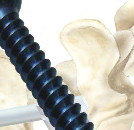
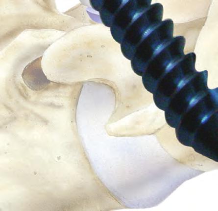
![SCREW INSERTION Attach the Screwdriver [119011] to the T-Handle [119008]. Select the desired screw diameter and length.](/docs-images/89/99382503/images/7-0.jpg "Attach selected screw to the Screwdriver assembly by inserting the sides of the screw head into the cut-outs of the Screwdriver shaft.")


7 SCREW INSERTION Attach the Screwdriver [119011] to the T-Handle [119008]. Select the desired screw diameter and length. Attach selected screw to the Screwdriver assembly by inserting the sides of the screw head into the cut-outs of the Screwdriver shaft. Push the screw head into the shaft of the driver to allow the tangs on the shaft of the driver to slide into two groves on opposite sides of the bone screw. Turn the knob clockwise to lock the screw to the driver providing a toggle-free screw/driver interface. Important: Continuously monitor the Guidewire to ensure it is not being advanced while inserting the screw to avoid penetration of the anterior wall of the vertebral body. Slide the screw and driver over the Guidewire, which will run through the shaft of the driver and out of the center of the T-handle. Advance the screw using a clockwise rotation on the ratcheting T-handle. Remove the Guidewire after the screw has been advanced 2 3 revolutions. The screw should be fully inserted into the pedicle with the shoulder of the bone screw sitting in the recess created previously with the Rasp. Given the design of the Securis pedicle screw, full polyaxial motion is maintained with a fully seated bone screw. Using fl uoroscopy, confi rm the position of the bone screw. To disengage the bone screw, turn the knob in a counter clockwise motion. To disengage the bone screw, turn the knob in a counter clockwise motion until the spring-loaded knob pops-up vertically, a signal that the driver is fully released from the screw. Screwdriver [119011] T-Handle [119008] CUSTOM SPINE, INC. I 7

![Screw Adjuster [119012] ROD SELECTION Once all pedicle screws are inserted, select the desired rod length.](/docs-images/89/99382503/images/8-1.jpg "The Cobalt-Chrome rods are 5.0mm in diameter with a choice of pre-bent rods in 35 70mm lengths and straight rods in 80 240mm lengths.")
![Rod Bender [119016] When rod contouring is desired, use the Rod Bender [119016] to contour the selected rod as needed by inserting](/docs-images/89/99382503/images/8-3.jpg "the rod into the head of the bender and compressing the handles.")
8 SCREW HEAD POSITIONING For successful rod insertion, the screw heads must be in alignment. Attach the T-handle to the Screw Adjuster [119012]. Manipulate the screw heads as needed to ensure proper alignment. Screw Adjuster [119012] ROD SELECTION Once all pedicle screws are inserted, select the desired rod length. The Cobalt-Chrome rods are 5.0mm in diameter with a choice of pre-bent rods in 35 70mm lengths and straight rods in mm lengths. Rod Bender [119016] When rod contouring is desired, use the Rod Bender [119016] to contour the selected rod as needed by inserting the rod into the head of the bender and compressing the handles. Tip: Do not bend the rod in reverse after initial contour in order to optimize the mechanical integrity of the rod. 8 I SECURIS Pedicle Screw System
![ROD INSERTION Use the Rod Inserter [119017] to place the rod in the previously aligned screw heads for retractor and open access procedures.](/docs-images/89/99382503/images/9-0.jpg "For percutaneous procedures, follow the instructions for rod insertion provided with the system. Rod Inserter [119017] Grip the middle of the rod with the pivoting Rod Inserter.")


9 ROD INSERTION Use the Rod Inserter [119017] to place the rod in the previously aligned screw heads for retractor and open access procedures. For percutaneous procedures, follow the instructions for rod insertion provided with the system. Rod Inserter [119017] Grip the middle of the rod with the pivoting Rod Inserter. Once the rod is secure, pivot the tip so that the rod is somewhat parallel to the Rod Inserter. Place the end of the rod into the caudal screw head and apply pressure to the rod, which will allow the rod to articulate from the vertical to horizontal position. Place the rod in the screw heads, then disengage the instrument to release the rod. Note: It is recommended that approximately 4mm of the rod extend beyond the head of the screw on both the superior and inferior ends of the construct. In addition, the pivoting grip of the Rod Inserter requires regular oiling to maintain smooth articulation. BLOCKER INSERTION The Blocker Inserter [119015] is double-ended allowing a blocker to be attached at both ends. Attach the blocker to the Blocker Inserter by simply pressing down on the blocker and insert into the screw head. Insert the blocker into the screw head by turning clockwise until fi nger tight. At this point the blocker is ready for fi nal-tightening. Note: Inspect each screw head to ensure the rod is fully seated before attempting to insert the blocker. If the rod sits proud in any of the screw heads, follow the rod reduction instructions to fully seat the rod. Once the rod is fully seated in the screw head, insert the blocker through the Rod Reducer to the screw head and tighten. Blocker Inserter [119015] 15] CUSTOM SPINE, INC. I 9
![ROD REDUCTION In some cases, it may be necessary to reduce the rod into the screw head. The Rod Reducer [119019] is designed to achieve up to 10mm in reduction.](/docs-images/89/99382503/images/10-0.jpg "Align the sides of the Rod Reducer shaft with the sides of the screw head allowing the rod to fi t in the aligned cut-outs of the screw head and reducer shaft.")

10 ROD REDUCTION In some cases, it may be necessary to reduce the rod into the screw head. The Rod Reducer [119019] is designed to achieve up to 10mm in reduction. Align the sides of the Rod Reducer shaft with the sides of the screw head allowing the rod to fi t in the aligned cut-outs of the screw head and reducer shaft. Ensure the tangs of the Rod Reducer shaft fi t into the grooves of the bone screw. Once in alignment, squeeze the ratcheting scissor handle to fully seat the rod. Insert the blocker inserter with blocker attached through the shaft of the Rod Reducer and insert the blocker to fi nger tight. Rod Reducer [119019] 10 I SECURIS Pedicle Screw System


11 SCREW ADJUSTMENT In some cases, the bone screw may need to be adjusted to fully seat the rod. Use the Screw Adjuster [119012] to make fi ne adjustments to the bone screw. Attach the Screw Adjuster to the T-handle. Position the Screw Adjuster in the screw head so that the sides of the screw insert over the cut-out in the shaft of the Screw Adjuster. Position the tangs on the end of the Screw Adjuster into the grooves of the bone screw. Rotate to achieve desired height and position. Screw Adjuster [119012] CUSTOM SPINE, INC. I 11


![Use the Standard Distractor [119013] to ratchet open the distractor legs to the desired position.](/docs-images/89/99382503/images/12-3.jpg "For removal, release the tension by applying slight distraction force between screw heads, then disengage the blockers and remove the Rack Distractor.")
12 DISTRACTION The Securis pedicle screw system offers three distraction options. Option1: Rack Distractor [119014] Once the screws have been placed, rotate the screw heads so that the rod cut-out is positioned medial-lateral. Insert the spherical legs of the Rack Distractor into the desired screw heads using the Rod Inserter. Pivot the distractor medially by pushing on the ratcheting slide bar to provide a lateral working window. Insert the blockers and lightly fi nger tighten to temporarily secure the Rack Distractor. Use the Standard Distractor [119013] to ratchet open the distractor legs to the desired position. For removal, release the tension by applying slight distraction force between screw heads, then disengage the blockers and remove the Rack Distractor. Option 2: Standard Distractor [119013] At this time, the vertebral motion segment has a bone screw inserted on adjacent levels of the disc space. Tighten the blocker on one of these bone screws and do not tighten the adjacent level blocker where distraction is desired. Place the Standard Distractor on the rod between the screw heads. Distraction is achieved by squeezing the ratcheting distraction handles. Tighten the adjacent blocker while maintaining distraction. Option 3: Compressor/Distractor [119020] For distraction, place the angled end of the Compressor/Distractor [119020] on the rod and against the screw head. Ensure that the screw you are distracting against has been fi nal tightened and that a blocker has been inserted and fi nger tightened on the screw from which you are distracting. Place the Counter Torque Wrench [119021] on the head if the screw you are distracting which has the fi nger tightened blocker. The Compressor/Distractor should be positioned against the screw head which has been fi nal tightened. 12 I SECURIS Pedicle Screw System Lever the Compressor/Distractor towards the counter Torque Wrench until the desired distraction is achieved. Insert the Torque Wrench into the Counter Torque Wrench and fi nal tighten.


![in the Compressor /Distractor [119020] and rotate the Counter Torque Wrench 90 degrees.](/docs-images/89/99382503/images/13-3.jpg "Apply the Counter Torque Wrench on the head of the screw which has the fi nger tightened blocker.")


13 COMPRESSION When performing compression, ensure that the screw you are compressing against has been fi nal tightened and that a blocker has been inserted and fi nger tightened on the screw to which you are compressing. Insert the fl at sides of the distal end of the Counter Torque Wrench [119021] through the cut-out in the Compressor /Distractor [119020] and rotate the Counter Torque Wrench 90 degrees. Apply the Counter Torque Wrench on the head of the screw which has the fi nger tightened blocker. The compressor should be attached to the screw head which has been fi nal tightened. Lever the Compressor/Distractor towards the Counter Torque Wrench until the desired compression is achieved. Insert the Torque Wrench into the counter Torque Wrench and fi nal tighten. Note: Not using the counter torque wrench during fi nal tightening may damage the screw and/or blocker or may lead to construct loosening. Compressor/Distractor [119020] Counter Torque Wrench [119021] CUSTOM SPINE, INC. I 13

14 FINAL TIGHTENING The torque limiting handle has a prescribed 9.5Nm of torque. Once this limit is achieved, the torque handle skips ensuring the appropriate amount of torque is applied without a breakaway once achieved. Place the Counter Torque Wrench [119021] over the screw head. Once secure to the screw, insert the Final Tightener [119018] with Ratcheting Torque Handle [119009] attached, into the Counter Torque Wrench and affi x into the blocker. Turn the torque limiting handle clockwise until the resistance releases and you can feel the handle skipping. Note: Not using the counter torque wrench during fi nal tightening may damage the screw and/or blocker or lead to construct loosening. Final Tightener [119018] Ratcheting Torque Handle [119009] 14 I SECURIS Pedicle Screw System
![REVISION/REMOVAL For removal of the construct, attach the ratcheting T-handle [119008] to the Final](/docs-images/89/99382503/images/15-0.jpg "Tightener [119018].")


![Once the blockers have been removed, used the Rod Inserter [119017] to remove the rods.](/docs-images/89/99382503/images/15-3.jpg "To remove the screws, insert the tip of the Revision Tool [119022] with T-handle attached into the")
15 REVISION/REMOVAL For removal of the construct, attach the ratcheting T-handle [119008] to the Final Tightener [119018]. Place the Counter Torque Wrench on the screw, and place the fi nal tightener through the Counter Torque Wrench into the screw head. Rotate the T-handle on the Final Tightener counterclockwise to loosen and remove blockers with the self-retaining Blocker Inserter. Once the blockers have been removed, used the Rod Inserter [119017] to remove the rods. To remove the screws, insert the tip of the Revision Tool [119022] with T-handle attached into the screw head. Rotate the T-handle clockwise until moderately tight. Release the T-handle. To remove the screw, rotate the Revision Tool counter clockwise using the integrated handle. Revision Tool [119022] CUSTOM SPINE, INC. I 15
![IMPLANTS AND INSTRUMENTS SET Securis Pedicle Screw System Tray 1 [119100] IMPLANTS LOWER LEVEL Product Number Description Quantity 115530 5.5mm x 30mm cannulated screw 4 115535 5.](/docs-images/89/99382503/images/16-0.jpg "5mm x 35mm cannulated screw 6 115540 5.5mm x 40mm cannulated screw 6 115545 5.5mm x 45mm cannulated screw 6 115550 5.5mm x 50mm cannulated screw 4 116535 6.5mm x 35mm cannulated screw 4 116540 6.")
16 IMPLANTS AND INSTRUMENTS SET Securis Pedicle Screw System Tray 1 [119100] IMPLANTS LOWER LEVEL Product Number Description Quantity mm x 30mm cannulated screw mm x 35mm cannulated screw mm x 40mm cannulated screw mm x 45mm cannulated screw mm x 50mm cannulated screw mm x 35mm cannulated screw mm x 40mm cannulated screw mm x 45mm cannulated screw mm x 50mm cannulated screw mm x 55mm cannulated screw mm x 35mm cannulated screw mm x 40mm cannulated screw mm x 45mm cannulated screw mm x 50mm cannulated screw mm x 55mm cannulated screw mm curved rod mm curved rod mm curved rod mm curved rod mm curved rod mm curved rod mm curved rod mm curved rod mm straight rod mm straight rod mm straight rod mm straight rod Blocker 20 *80, 90 and 100mm curved rods available upon request 16 I SECURIS Pedicle Screw System
![IMPLANTS AND INSTRUMENTS SET Securis Pedicle Screw System Tray 1 [119100] INSTRUMENTS UPPER LEVEL Product Number Description Quantity 119001 Guidewire 12 119002 Rasp 1 119003 Tap 5.](/docs-images/89/99382503/images/17-0.jpg "5mm 1 119004 Tap 6.5mm 1 119005 Tap 7.")
17 IMPLANTS AND INSTRUMENTS SET Securis Pedicle Screw System Tray 1 [119100] INSTRUMENTS UPPER LEVEL Product Number Description Quantity Guidewire Rasp Tap 5.5mm Tap 6.5mm Tap 7.5mm Wire Holder Ratcheting T-Handle Ratcheting Torque Handle Blocker Inserter Final Tightener 2 CUSTOM SPINE, INC. I 17
![IMPLANTS AND INSTRUMENTS SET Securis Pedicle Screw System Tray 2 [119100] INSTRUMENTS UPPER LEVEL Product Number](/docs-images/89/99382503/images/18-0.jpg "Description Quantity 119011 Screwdriver 2 119012 Screw Adjuster 1 119013 Distractor 1 119014 Rack Distractor 1")

18 IMPLANTS AND INSTRUMENTS SET Securis Pedicle Screw System Tray 2 [119100] INSTRUMENTS UPPER LEVEL Product Number Description Quantity Screwdriver Screw Adjuster Distractor Rack Distractor Rod Bender Rod Inserter 1 INSTRUMENTS LOWER LEVEL Product Number Description Quantity Rod Reducer Compressor Counter Torque Wrench Revision Tool 1 18 I SECURIS Pedicle Screw System
19 CUSTOM SPINE CUSTOM SPINE Securis Pedicle Screw System CAUTION: Federal law (U.S.A.) restricts this device to sale by or on the order of a licensed physician. NON STERILE PRODUCT MUST BE STERILIZAED PRIOR TO USE SINGLE USE ONLY THE SECURIS PEDICLE SCREW SYSTEM HAS NOT BEEN EVALUATED FOR SAFETY AND COMPATABILITY IN THE MR ENVIRONMENT. THE SECURIS SPINAL FIXATION SYSTEM HAS NOT BEEN TESTED FOR HEATING OR MIGRATION IN THE MR ENVIRONMENT. SECURIS PECICLE SCREW CONNECTORS ARE USED FOR PEDICULAR FIXATION IN THE IMMOBILIZATION AND STABILIZATION OF THE POSTERIOR NON CERVICAL (T1-S1) SPINE. NON STERILE PRODUCT The Custom Spine Securis Pedicle Screw System is comprised of spinal implants for fixation of the non-cervical spine. This includes: rods, screws and blockers. The components are manufactured from titanium alloy and chromium-cobalt. The screws are available in various sizes from 5.5mm to 7.5mm diameters with lengths ranging from 30mm to 55mm. MATERIALS Titanium alloy: Ti6-Al-4V according to ISO , ASTM F-136 and Chromium-Cobalt, ASTM F-1537: (NOTE: Titanium and stainless steel implants should not be mixed in patients as corrosion may occur resulting in decreased mechanical performance) INDICATIONS The FDA regulation restricts the use of pedicle screw fixation as follows: The SECURIS Spinal Fixation System is intended for the immobilization and stabilization of the thoraco-lumbar-sacral spine (T1-S1) as an adjunct to fusion in skeletally mature patients for the following indications: degenerative disc disease (defined as discogenic back pain with degeneration of the disc confirmed by history and radiographic studies), spondylolisthesis,fracture,dislocation,scoliosis,kyphosis,spinal tumor, and previously failed fusion (pseudoarthrosis). CONTRAINDICATIONS Contraindications may be relative or absolute. The choice of a particular device must be carefully weighed against the patient s overall evaluation. Circumstances listed below may reduce the chances of a successful outcome: Any abnormality present which affects the normal process of bone remodeling including, but not limited to, severe osteoporosis involving the spine, active infection at the site or certain metabolic disorders affecting osteogenesis. Insufficient quality or quantity of bone which would inhibit rigid device fixation. Previous history of infection. Excessive local inflammation. Open wounds. Any neuromuscular deficit which places an unusually heavy load on the device during the healing period. Obesity. An overweight or obese patient can produce loads on the spinal system which can lead to failure of the fixation of the device or to failure of the device itself. Patients having inadequate tissue coverage of the operative site. Pregnancy. A condition of senility, mental illness, or substance abuse. These conditions, among others, may cause the patient to ignore certain necessary limitations and precautions in the use of the implant, leading to failure or other complications. Foreign body sensitivity. Where material sensi tivity is suspected, appropriate tests should be made prior to material selection or implantation. Other medical or surgical conditions which would preclude the potential benefit of spinal implant surgery, such as the presence of tumors, congenital abnormalities, elevation of sedimentation rate unexplained by other diseases, elevation of white blood cell count (WBC), or marked left shift in the WBC differential count. These contraindications can be relative or absolute and must be taken into account by the physician when making his decision. The above list is not exhaustive. CAUTION: Federal law (U.S.A.) restricts this device to sale by or on the order of a licensed physician. Pedicle Screw implantation should only be performed by experienced spinal surgeons with specific training in the use of the Securis Spinal Fixation System. This is a technically demanding procedure with a risk of serious patient injury. The safety and effectiveness of pedicle screw spinal systems have been established only for spinal conditions with significant mechanical instability or deformity requiring fusion with instrumentation. These conditions are significant mechanical instability or deformity of the thoracic, lumbar, and sacral spine secondary to spondylolisthesis (grades 3 and 4) of the L5-S1vertebrae, degenerative spondylolisthesis with objective evidence of neurological impairment, fracture dislocation, scoliosis, kyphosis, spinal tumor, and failed pervious fusion. (Pseudoarthrosis) The safety and effectiveness of these devices for any other conditions are unknown. CUSTOM SPINE, INC. I 19
20 Custom Spine, Inc. 9 Campus Drive Parsippany, NJ Phone (973) Fax (877) Product Number Rev. B
A U X I L I A R Y C O N N E C T O R S Surgical Technique
 A U X I L I A R Y C O N N E C T O R S Surgical Technique AUXILIARY CONNECTORS ISSYS LP Auxiliary Connectors The ISSYS LP auxiliary connectors were designed to provide medial-lateral variability for the
Y o u r Id e a s En g i n e e r e d t o Li f e
 ISSYS LP Spinal Fixation System Surgical Guide Y o u r Id e a s En g i n e e r e d t o Li f e In t r o d u c t i o n ISSYS LP Sp i n a l Fixation System The foundation of the ISSYS LP Spinal Fixation System
Thunderbolt. surgical technique. MIS Pedicle Screw System. Where Nimble and Secure Intersect
 Thunderbolt TM MIS Pedicle Screw System Where Nimble and Secure Intersect surgical technique i www.choicespine.com System Features Dovetail set screw: Minimizes head splay and cross-threading Secure connection
EXCELLA ll. Spinal System
 EXCELLA ll Spinal System Excella II Spinal System INDICATIONS FOR USE The Innovasis Excella II Spinal System is intended for use in the non-cervical area of the spine. WARNING: The safety and effectiveness
Threshold Pedicular Fixation System Surgical Technique
 Threshold Pedicular Fixation System Surgical Technique Table of Contents Patient Preparation and Positioning... 2 Determining Incision Location... 3 Assembling the Cannulated Awl... 4 Guide Wire Placement...
 Visit our website on www.biotech-medical.com The DLP - Dorso-Lumbar Polyaxial Screw System has been designed to address the pathologies of the thoracolumbar spine. The DLP System contains a wide range
TiLock XT Minimally Invasive Surgery (MIS) Pedicle Screw System
 Pedicle Screw System") TiLock XT Minimally Invasive Surgery (MIS) Pedicle Screw System The Genesys Spine TiLock XT Minimally Invasive Surgery (MIS) Pedicle Screw System consists of rods (straight and curved), lock screws, and
TiLock XT Minimally Invasive Surgery (MIS) Pedicle Screw System The Genesys Spine TiLock XT Minimally Invasive Surgery (MIS) Pedicle Screw System consists of rods (straight and curved), lock screws, and
HydraLok. Operative Technique. Polyaxial Pedicle Screw System
 HydraLok Operative Technique Polyaxial Pedicle Screw System Table of Contents Introduction...1 OPERATIVE TECHNIQUE OVERVIEW...2 DETAILED OPERATIVE TECHNIQUE...4 LOCATE AND PREPARE THE PEDICLE...4 PROBE
VTI INTERLINK PEDICLE SCREW SYSTEM
 VTI INTERLINK PEDICLE SCREW SYSTEM SURGICAL TECHNIQUE FORWARD THINKING FOR THE BACK. DEVICE DESCRIPTION The VTI InterLink Pedicle Screw System is comprised of polyaxial pedicle screws in various diameters
X-spine Surgical Technique
 X-spine Surgical Technique The X90 Pedicle Screw System Revolutionary Design and Function This document is intended exclusively for experts in the field, particularly physicians, and is not intended for
TiLock XT Minimally Invasive Surgery (MIS) Pedicle Screw System
 Pedicle Screw System") Minimally Invasive Surgery (MIS) Pedicle Screw System Surgical Technique Guide 2 Minimally Invasive Surgery (MIS) Pedicle Screw System The Genesys Spine Minimally Invasive Surgery (MIS) Pedicle Screw System
Minimally Invasive Surgery (MIS) Pedicle Screw System Surgical Technique Guide 2 Minimally Invasive Surgery (MIS) Pedicle Screw System The Genesys Spine Minimally Invasive Surgery (MIS) Pedicle Screw System
Table of Contents.
 surgical technique The Ambassador TM Anterior Cervical Plate System is a versatile system of implants and instruments with a variety of sizes to provide optimal anatomic compatibility. The integrated cam
nva Anterior Lumbar Interbody Fusion System
 nva Anterior Lumbar Interbody Fusion System 1 IMPORTANT INFORMATION FOR PHYSICIANS, SURGEONS, AND/OR STAFF The nv a, nv p, and nv t are an intervertebral body fusion device used in the lumbar spine following
Valencia Pedicle Screw Surgical Technique
 Valencia Pedicle Screw Surgical Technique VALENCIA CIRCUIT TABLE OF CONTENTS Design Rationale Indications for Use Surgical Technique 1. Pedicle Preparation 2. Screw Insertion 3. Rod Placement 4. Locking
SURGICAL TECHNIQUE GUIDE TRESTLE. Anterior Cervical Plating System
 SURGICAL TECHNIQUE GUIDE TRESTLE Anterior Cervical Plating System 2 SURGICAL TECHNIQUE GUIDE SURGICAL TECHNIQUE GUIDE System Features Large window enables visualization of graft site and end plates Screw
nvt Transforaminal Lumbar Interbody Fusion System
 nvt Transforaminal Lumbar Interbody Fusion System 1 IMPORTANT INFORMATION FOR PHYSICIANS, SURGEONS, AND/OR STAFF The nv a, nv p, and nv t are an intervertebral body fusion device used in the lumbar spine
operative technique Universal Application
 operative technique Universal Application Introduction Introduction Building upon the design rationale of the Xia Spinal System, the new Xia Spinal System represents the latest advancement in spinal implant
TiLock 2 Spinal System. Surgical Technique
 TiLock 2 Spinal System Surgical Technique Table of Contents Page Preoperative Planning 4 Pedicle Preparation 5 Probe 5 Tap Pedicle 6 Screw Options 7 Screw Insertion 8 Aligning the Windows 9 Rod Insertion
nvp Posterior Lumbar Interbody Fusion System
 nvp Posterior Lumbar Interbody Fusion System 1 IMPORTANT INFORMATION FOR PHYSICIANS, SURGEONS, AND/OR STAFF The nv a, nv p, and nv t are an intervertebral body fusion device used in the lumbar spine following
TM TM Surgical Technique
 TM TM Surgical Technique TABLE OF CONTENTS Reli SP Spinous Plating System Overview Device Description Implant Features Indications Instruments Access Instruments Preparation Instruments Insertion Instruments
ACP. Anterior Cervical Plate System SURGICAL TECHNIQUE
 ACP Anterior Cervical Plate System SURGICAL TECHNIQUE ACP TABLE OF CONTENTS INTRODUCTION 4 INDICATIONS AND CONTRAINDICATIONS 5 WARNINGS AND PRECAUTIONS 6 IMPLANT DESCRIPTION 7 INSTRUMENTS 10 SURGICAL
EXACTECH SPINE. Operative Technique. Cervical Spacer System. Surgeon focused. Patient driven. TM
 EXACTECH SPINE Operative Technique Cervical Spacer System Surgeon focused. Patient driven. TM ACAPELLA ONE Acapella One Cervical Spacer System is an anterior cervical discectomy and fusion device with
USS Variable Axis Screw (VAS) System. For posterior fixation of the lumbar spine.
 System. For posterior fixation of the lumbar spine.") USS Variable Axis Screw (VAS) System. For posterior fixation of the lumbar spine. Technique Guide Instruments and implants approved by the AO Foundation Table of Contents Introduction USS Variable Axis
USS Variable Axis Screw (VAS) System. For posterior fixation of the lumbar spine. Technique Guide Instruments and implants approved by the AO Foundation Table of Contents Introduction USS Variable Axis
O PE RATIV E TE C HN IQ U E. Minimally Invasive Posterior Fixation
 O PE RATIV E TE C HN IQ U E TM Minimally Invasive Posterior Fixation Table of Contents 1 PRE-OPERATIVE PLANNING Patient Positioning Pedicle Identification and Incision Planning 4 OPERATIVE TECHNIQUE Incision
ONE SYSTEM, MULTIPLE OPTIONS. Surgical Technique. Hip Knee Spine Navigation
 ONE SYSTEM, MULTIPLE OPTIONS Surgical Technique Hip Knee Spine Navigation MUST MINI Surgical Technique Hip Knee Spine Navigation INTRODUCTION The M.U.S.T. Mini posterior cervical screw system is a modular
EXCELLA MIS. Spinal System
 EXCELLA MIS Spinal System Excella MIS Spinal System INDICATIONS FOR USE The Innovasis Excella MIS Spinal System is intended for use in the non-cervical area of the spine. WARNING: The safety and effectiveness
100 Interpace Parkway Parsippany, NJ
 100 Interpace Parkway Parsippany, NJ 07054 www.biometspine.com 800-526-2579 All trademarks are the property of Biomet, Inc. or one of its subsidiaries, unless otherwise indicated. Rx Only. 2009 EBI, LLC.
L8 Spine System SURGICAL TECHNIQUE. Add: No.1-8, Tianshan Road, Xinbei District, Changzhou, Jiangsu, China
 Add: No.-8, Tianshan Road, Xinbei District, Changzhou, Jiangsu, China 23022 Tel: 0086 59 8595556 Fax: 0086 59 859555 Http://www.kanghui.com Add: F25, Shanghai International Pharmaceutical Trad & Exhibition
Ballista Percutaneous Screw Placement System. Surgical Technique
 Ballista Percutaneous Screw Placement System Surgical Technique Contents Introduction... Page 1 Features And Benefits... Page 2 Implants... Page 3 Instruments... Page 4 Surgical Technique... Page 8 Indications
Thoracolumbar Spine Locking Plate (TSLP) System. A low-profile plating system for anterior stabilization of the thoracic and lumbar spine.
 System. A low-profile plating system for anterior stabilization of the thoracic and lumbar spine.") Thoracolumbar Spine Locking Plate (TSLP) System. A low-profile plating system for anterior stabilization of the thoracic and lumbar spine. Technique Guide Instruments and implants approved by the AO Foundation
Thoracolumbar Spine Locking Plate (TSLP) System. A low-profile plating system for anterior stabilization of the thoracic and lumbar spine. Technique Guide Instruments and implants approved by the AO Foundation
Technique Guide. MATRIX Spine System MIS Instrumentation. The total solution for simple and complex spine pathology.
 Technique Guide MATRIX Spine System MIS Instrumentation. The total solution for simple and complex spine pathology. Table of Contents Introduction MATRIX Spine System MIS Instrumentation 2 AO Principles
Surgical Technique Manual
 Surgical Technique Manual Surgeon Designers Richard G. Fessler, MD, PhD Northwestern University, Chicago, IL Robert A. Hart, MD Oregon Health and Science University, Portland, OR Robert Labrom, MD Queensland
The Most Reliable Spinal Solution
 MFG : 09.02.20 REV : 1 4CIS VANE introduces you the reliable pedicle screw The Most Reliable Spinal Solution Non-slip threaded joint Ergonomic design Wedged trapezoid thread Superior locking mechanism
Zimmer Facet Screw System Surgical Technique
 Zimmer Facet Screw System Surgical Technique 2 Zimmer Facet Screw System Surgical Technique Zimmer Facet Screw System Surgical Technique Description, Indications & Contraindications...3 Surgical Technique...4
Royal Oak Cervical Plate System
 Royal Oak Cervical Plate System Manufactured by Nexxt Spine, Inc. Royal Oak Cervical Plate System INTRODUCTION FEATURES AND BENEFITS Table of Contents SURGICAL TECHNIQUE Step 1. Patient Positioning Step
ACP1 CERVICAL PLATE SPINAL SYSTEM SURGICAL TECHNIQUE GUIDE II.
 I. ACP1 CERVICAL PLATE II. SPINAL SYSTEM SURGICAL TECHNIQUE GUIDE I. Introduction The Gold Standard Orthopaedics, LLC ACP1 Spinal System was designed with surgeons to incorporate strength, functionality,
Veyron -C Anterior Cervical System Surgical Technique
 Veyron -C Anterior Cervical System Surgical Technique 2 Veyron-C Anterior Cervical System Surgical Technique Veyron-C Anterior Cervical System Surgical Technique Description, Indications & Contraindications...3
Cervical Spacer System surgical technique
 Blackhawk TM Cervical Spacer System surgical technique Blackhawk TM The BLACKHAWK Cervical Spacer System is designed to provide biomechanical stabilization as an adjunct to fusion. Spinal fixation should
INTELLIGENT SPINAL SYSTEM
 INTELLIGENT SPINAL SYSTEM I. Introduction II. Product Specification III. Surgical Technique IV. Ordering Information V. IFU for Lospa IS SPINAL SYSTEM The LOSPA IS spinal system consists of
Ballista Percutaneous Screw Placement System
 Surgical Technique Ballista Percutaneous Screw Placement System A Minimally Invasive Approach for Posterior Spinal Surgery True percutaneous system Helical Flange locking mechanism Contents Introduction...
Ref: Q400-09T1 EBI Spine. September 05/VS02. c/o BIOMET Spain Orthopaedics, S.L.
 Ref: Q400-09T1 EBI Spine. September 05/VS02 c/o BIOMET Spain Orthopaedics, S.L. www.ebimedical.com EBI Omega 21 TM LP Since its introduction in 1996, and with thousands of patients treated so far, the
Alamo C. Cervical Interbody System Surgical Technique. An Alliance Partners Company
 Cervical Interbody System Surgical Technique Table of Contents Indications for Use................................1 Device Description............................... 1 Alamo C Instruments..............................
MEDACTA UNCONSTRAINED SCREW TECHNOLOGY - REDUCTION SCREWS. Surgical Technique. Hip Knee Spine Navigation
 .U.S.T. MEDACTA UNCONSTRAINED SCREW TECHNOLOGY - REDUCTION SCREWS Hip Knee Spine Navigation M.U.S.T. Hip Knee Spine Navigation INTRODUCTION The Medacta Unconstrained Screw Technology [M.U.S.T.] Pedicle
Dymaxeon Spine System. Simple, Streamlined, Smart. Surgical Procedure
 Simple, Streamlined, Smart Surgical Procedure Introduction The Dymaxeon pedicle screw system offers the spinal surgeon an outstanding system for stabilization of spinal deformity, reduction of spondylolisthesis,
Royal Oak IBFD System Surgical Technique Posterior Lumbar Interbody Fusion (PLIF)
") Royal Oak IBFD System Surgical Technique Posterior Lumbar Interbody Fusion (PLIF) Preoperative Planning Preoperative planning is necessary for the correct selection of lumbar interbody fusion devices.
Royal Oak IBFD System Surgical Technique Posterior Lumbar Interbody Fusion (PLIF) Preoperative Planning Preoperative planning is necessary for the correct selection of lumbar interbody fusion devices.
VECTRA-T SURGICAL TECHNIQUE. The Translational Anterior Cervical Palate System. This publication is not intended for distribution in the USA.
 VECTRA-T The Translational Anterior Cervical Palate System This publication is not intended for distribution in the USA. SURGICAL TECHNIQUE Image intensifier control This description alone does not provide
Surgical Technique Guide
 Sacroiliac Joint Fusion System Surgical Technique Guide Moving Life Forward Table of Contents SiCure Implant Overview...2 SiCure System Information...3 X-ray Basics...4 Patient Positioning....5 Surgical
Technique Guide MAXIMUM ACCESS SURGICAL PLATFORM
 Technique Guide MAXIMUM ACCESS SURGICAL PLATFORM MAXIMUM ACCESS SURGICAL PLATFORM CONTENTS Preface 1 SpheRx II Anterior Technique Guide 2 Equipment Requirements 2 Patient Positioning and O.R. Setup 2 Staple
SerratoTM. Surgical technique
 TM Surgical technique Table of contents Key design features.... 3 System overview.... 4 Surgical technique Patient positioning... 7 Preparing the pedicle.... 8 Screw insertion... 11 Rod contouring... 12
Alamo T Transforaminal Lumbar Interbody System Surgical Technique
 Transforaminal Lumbar Interbody System Surgical Technique Table of Contents Indications and Device Description.............. 1 Alamo T Implant Features and Instruments...........2 Surgical Technique......................
A Fusion of Versatility, Performance and Ease.
 MATRIX Spine System. Degenerative and Deformity. System Guide A Fusion of Versatility, Performance and Ease. Instruments and implants approved by the AO Foundation The MATRIX Spine System is a universal
OPERATIVE TECHNIQUE. anterior cervical plating system
 OPERATIVE TECHNIQUE 3º anterior cervical plating system Introduction 1 Pre-Operative Technique 2 Oerative Technique 3 Instructions for Use 12 Part Numbers 16 The surgical technique shown is for illustrative
TABLE OF CONTENTS. Vault C Anterior Cervical Discectomy 2 and Fusion (ACDF) System Overview. Implants 3. Instruments 5. Surgical Technique 10
 System Overview. Implants 3. Instruments 5. Surgical Technique 10") Surgical Technique TABLE OF CONTENTS Vault C Anterior Cervical Discectomy 2 and Fusion (ACDF) System Overview Indications 2 Implants 3 Instruments 5 Surgical Technique 10 1. Preoperative planning 10 2.
Surgical Technique TABLE OF CONTENTS Vault C Anterior Cervical Discectomy 2 and Fusion (ACDF) System Overview Indications 2 Implants 3 Instruments 5 Surgical Technique 10 1. Preoperative planning 10 2.
SURGICAL TECHNIQUE GUIDE SOLANAS. Posterior Cervico-Thoracic Fixation System Adjustable Bridge System
 SURGICAL TECHNIQUE GUIDE SOLANAS Posterior Cervico-Thoracic Fixation System Adjustable Bridge System 2 SURGICAL TECHNIQUE GUIDE Preface SOLANAS Posterior Cervico-Thoracic Fixation System is designed to
Zimmer Anterior Buttress Plate System. Surgical Technique
 Zimmer Anterior Buttress Plate System Surgical Technique 2 Zimmer Anterior Buttress Plate System Surgical Technique Zimmer Anterior Buttress Plate System Surgical Technique Description, Indications & Contraindications...
EXPEDIUM 5.5 Spine System Family Product Catalogue
 EXPEDIUM 5.5 Spine System Family Product Catalogue Including: EXPEDIUM EXPEDIUM Vertebral Body Derotation Universal Connector Set Cobalt Chromium Rods INTRODUCTION Contents EXPEDIUM Spine System is a comprehensive
HawkeyeTM Peek. surgical technique
 HawkeyeTM Peek surgical technique Introduction The ChoiceSpine HAWKEYE Vertebral Body Replacement (VBR) System is intended for use in the thoracolumbar spine (T1 - L5) to replace a collapsed, damaged,
ONE SYSTEM, MULTIPLE OPTIONS. Surgical Technique
 ONE SYSTEM, MULTIPLE OPTIONS Surgical Technique Joint Spine Sports Med M.U.S.T. Mini Surgical Technique 2 INDEX 1. INTRODUCTION 4 1.1 Indications 4 1.2 Contraindications 4 1.3 Pre-Operative Planning 5
Imola Lateral IBF System Surgical Technique
 Imola Lateral IBF System Surgical Technique IMOLA CIRCUIT TABLE OF CONTENTS Design Rationale Instructions for Use Surgical Technique 1. Table Mounting 2. Surgical Planning & Targeting 3. Access and Preparation
Technique Guide. Universal Spinal System (USS). Designed to achieve the goals of scoliosis surgery.
. Designed to achieve the goals of scoliosis surgery.") Technique Guide Universal Spinal System (USS). Designed to achieve the goals of scoliosis surgery. Table of Contents Introduction Universal Spinal System 2 AO ASIF Principles of Internal Fixation 3 Indications
Technique Guide Universal Spinal System (USS). Designed to achieve the goals of scoliosis surgery. Table of Contents Introduction Universal Spinal System 2 AO ASIF Principles of Internal Fixation 3 Indications
TECHNICAL BROCHURE. Capture Facet Fixation System
 TECHNICAL BROCHURE Capture Facet Fixation System Table of Contents Product Overview...2 Instruments...4 Capture Facet Screw Surgical Technique Patient Preparation and Positioning...6 Guide Pin Placement...7
GIZA Surgical Technique
 GIZA Surgical Technique Vertebral Body Replacement System Manufactured by Titanium alloy material provides mechanical integrity during insertion and distraction, x-ray visibility, and biocompatibility*
LUMBAR POSTERIOR MINIMALLY INVASIVE SYSTEM. Surgical Technique
 LUMBAR POSTERIOR MINIMALLY INVASIVE SYSTEM Surgical Technique Joint Spine Sports Med M.U.S.T. Mini Open Surgical Technique Joint Spine Sports Med CAUTION Federal law (USA) restricts this device to sale
I. II. SPINAL SYSTEM SURGICAL TECHNIQUE GUIDE
 I. GS1 II. SPINAL SYSTEM SURGICAL TECHNIQUE GUIDE Introduction The Gold Standard Orthopaedics, LLC GS1 Spinal System designed in conjunction with Richard Holt, M.D. incorporates both strength and function
Surgical Technique 1
 1 Surgical Technique TELLURIDE 2 MIS SPINAL FIXATION SYSTEM The Telluride 2 MIS Spinal Fixation System is a simple, robust and versatile minimally invasive pedicle screw system consisting of implants and
Technique Guide. NFlex. Semi-rigid rods for posterior lumbar stabilization.
 Technique Guide NFlex. Semi-rigid rods for posterior lumbar stabilization. Table of Contents Introduction NFlex 2 Indications and Contraindications 4 NFlex Principles 6 Surgical Technique Preoperative
LBL-014. Rev
 Package Insert Z- CLAMP ISP System Device Description: The Z-CLAMP ISP System is supplemental fixation device consisting of a variety of shapes and sizes of one-level lumbar and sacral plates and screws.
Solitaire Anterior Spinal System
 Surgical Technique Solitaire Anterior Spinal System Independent Stabilization for the Anterior Column Available in Titanium and Contents Introduction... Page 1 Design Features... Page 2 Instruments...
C-THRU Anterior Spinal System
 C-THRU Anterior Spinal System Surgical Technique Manufactured From Contents Introduction... Page 1 Design Features... Page 2 Instruments... Page 3 Surgical Technique... Page 4 Product Information... Page
Apache Cervical Interbody Fusion Device. Surgical Technique. Page of 13. LC-005 Rev F
 LC-005 Rev F Apache Cervical Interbody Fusion Device Page of 13 Surgical Technique INDICATIONS: When used as an intervertebral body fusion device, the Genesys Spine Interbody Fusion System is indicated
EFSPINE CERVICAL COMBINED SET DISC PROTHESIS ORGANIZER BOX
 EFSPINE CERVICAL COMBINED SET INSTRUMENTS CERVICAL CAGE & DISC PROTHESIS ORGANIZER BOX Cervical Thoracic Thoraco - Lumbar Sacral EFSPINE CERVICAL COMBINED SET CERVICAL IMPLANTS INTRODUCTION Cervical Disc
M.I.S. MAKE IT SMART IN ONE SYSTEM. Surgical Technique. Hip Knee Spine Navigation
 M.I.S. MAKE IT SMART IN ONE SYSTEM Surgical Technique Hip Knee Spine Navigation M.U.S.T. Mini Open Surgical Technique Hip Knee Spine Navigation 2 C O N T E N T S 1 INTRODUCTION 4 2 SURGICAL TECHNIQUE 5
Handling instructions. USS Low Profile. Thoracolumbar posterior fixation system.
 Handling instructions USS Low Profile. Thoracolumbar posterior fixation system. U Table of contents Introduction Indications and contraindications 3 USS Low Profile implants 4 Handling implants with stick
Dual-Opening USS. For deformity correction.
 Dual-Opening USS. For deformity correction. Technique Guide Instruments and implants approved by the AO Foundation Table of Contents Introduction Dual-Opening USS 2 AO Principles 4 Indications 5 Preoperative
Lumbar Dynamic. Reinhold Knebel Product Manager
 Lumbar Dynamic Reinhold Knebel Product Manager The DSS system provides options for dynamic and rigid stabilization to treat hypermobile segments and segments that require fusion. Allows pedicle displacement
Thoracolumbar Solutions. Cypher. MIS Screw System. Surgical Technique Guide
 Thoracolumbar Solutions Cypher MIS Screw System Surgical Technique Guide 2 Cypher MIS Screw System Surgical Technique Guide Game Changing Technology 3 mm of medial-lateral translation encourages optimal
Trinica and Trinica Select Anterior Cervical Plate System
 Surgical Technique Trinica and Trinica Select Anterior Cervical Plate System A New Twist to Anterior Cervical Plates Trinica and Trinica Select Surgical Technique 1 Trinica and Trinica Select Anterior
Technique Guide. 3.5 mm LCP Low Bend Medial Distal Tibia Plate Aiming Instruments. Part of the 3.5 mm LCP Percutaneous Instrument System.
 Technique Guide 3.5 mm LCP Low Bend Medial Distal Tibia Plate Aiming Instruments. Part of the 3.5 mm LCP Percutaneous Instrument System. Table of Contents Introduction 3.5 mm LCP Low Bend Medial Distal
LCP Medial Distal Tibia Plate, without Tab. The Low Profile Anatomic Fixation System with Angular Stability and Optimal Screw Orientation.
 LCP Medial Distal Tibia Plate, without Tab. The Low Profile Anatomic Fixation System with Angular Stability and Optimal Screw Orientation. Technique Guide LCP Small Fragment System Table of Contents Introduction
AccuVision Minimally Invasive Spinal Exposure System
 Surgical Technique AccuVision Minimally Invasive Spinal Exposure System Working Beyond the Tube Lighted blades for superior viewing Maximum stabilization Contents Introduction... Page 1 Features and Benefits...
Technique Guide. 3.5 mm LCP Low Bend Medial Distal Tibia Plates. Part of the Synthes locking compression plate (LCP) system.
 system.") Technique Guide 3.5 mm LCP Low Bend Medial Distal Tibia Plates. Part of the Synthes locking compression plate (LCP) system. Table of Contents Introduction 3.5 mm LCP Low Bend Medial Distal Tibia Plates
Technique Guide 3.5 mm LCP Low Bend Medial Distal Tibia Plates. Part of the Synthes locking compression plate (LCP) system. Table of Contents Introduction 3.5 mm LCP Low Bend Medial Distal Tibia Plates
Technique Guide. T-PAL. Transforaminal posterior atraumatic lumbar spacer system.
 Technique Guide T-PAL. Transforaminal posterior atraumatic lumbar spacer system. Table of Contents Introduction T-PAL 2 AO Principles 4 Indications and Contraindications 5 Surgical Technique Preparation
CSS Combined Spine System
 CSS Combined Spine System H- CSS Combined Spine System H- CSS Combined Spinal System : 800000 H-3 CSS Combined Spinal System : 800000 Ref.Number Description Pieces Ref.Number Description Pieces 00000 Open
UniLink Interspinous Fusion System UniLink 5/1 Interspinous Fusion System UniLink Graft. Surgical Technique
 UniLink Interspinous Fusion System UniLink 5/1 Interspinous Fusion System UniLink Graft Surgical Technique 2 UniLink and UniLink 5/1 Interspinous Fusion System Surgical Technique UniLink and Unlink 5/1
Surgical Technique FOR U.S. DOMESTIC USE ONLY
 Surgical Technique FOR U.S. DOMESTIC USE ONLY Polyaxial Screws HA Coated Polyaxial Screws Uniplanar Screws Reduction Screws Reduction Uniplanar Screws Modular Screws TABLE OF CONTENTS Reform Pedicle Screw
Asnis. Micro Cannulated screw system. Xpress operative technique
 Asnis Micro Cannulated screw system Xpress operative technique Asnis Micro Cannulated screw system Table of contents Indications, precautions & contraindications 3 Operative technique 4 This publication
MATRIX Spine System Deformity
 A Solution for Simple and Complex Spine Pathology MATRIX Spine System Deformity Surgical Technique Image intensifier control This description alone does not provide sufficient background for direct use
PILLAR AL. Anterior Lumbar Interbody Fusion (ALIF) and Partial Vertebral Body Replacement (pvbr) PEEK Spacer System OPERATIVE TECHNIQUE
 and Partial Vertebral Body Replacement (pvbr) PEEK Spacer System OPERATIVE TECHNIQUE") PILLAR AL PEEK Spacer System Anterior Lumbar Interbody Fusion (ALIF) and Partial Vertebral Body Replacement (pvbr) OPERATIVE TECHNIQUE Table of Contents 1 INTRODUCTION 2 PRE-OPERATIVE TECHNIQUE 3 OPERATIVE
PILLAR AL PEEK Spacer System Anterior Lumbar Interbody Fusion (ALIF) and Partial Vertebral Body Replacement (pvbr) OPERATIVE TECHNIQUE Table of Contents 1 INTRODUCTION 2 PRE-OPERATIVE TECHNIQUE 3 OPERATIVE
XRL A modular expandable radiolucent vertebral body replacement system
 XRL A modular expandable radiolucent vertebral body replacement system This publication is not intended for distribution in the USA. SURGICAL TECHNIQUE Table of Contents Introduction XRL 2 AO Spine Principles
TSLP Thoracolumbar Spine Locking Plate
 Anterior thoracolumbar spine locking plate TSLP Thoracolumbar Spine Locking Plate Surgical Technique Image intensifier control This description alone does not provide sufficient background for direct use
Surgical Technique. Available In Titanium And Stainless Steel
 Surgical Technique Available In Titanium And Stainless Steel Contents Introduction... Page 1 System Design Features... Page 2 Implants... Page 3 Standard Instruments... Page 7 Degenerative Surgical Technique...
The Versatile Polyaxial Solution for the Universal Spine Systems. USS II Polyaxial. Surgical Technique
 The Versatile Polyaxial Solution for the Universal Spine Systems USS II Polyaxial Surgical Technique Image intensifier control This description alone does not provide sufficient background for direct use
Cervical Screw System
 Cervical Screw System LnK Posterior Cervical Screw The LnK Cervical Fixation System provides a top-loading, simple and secure system for rigid fixation. The LnK Cervical Fixation system includes instrumentation
SURGICAL TECHNIQUE MANUAL. InterFuse T
 1 CONTENTS InterFuse T Product Description 3 Indications for Use 3 X-Ray Marker Locations 4 Product Specifications 4 Instrument Set 5 Step 1 Preoperative Planning 8 Patient Positioning 8 Step 2 Disc Removal
DIPLOMAT FIXATOR. open" and MIS" without having to change systems Spontaneous augmentation. Minimally invasive posterior instrumentation
 DIPLOMAT Minimally invasive posterior instrumentation open" and MIS" without having to change systems Spontaneous augmentation PRODUCT INFORMATION FIXATOR PRODUCT INFORMATION SIGNUS Medizintechnik GmbH
Low Bend Distal Tibia Plates
 Part of the DePuy Synthes Locking Compression Plate (LCP ) System 3.5 mm LCP Low Bend Medial Distal Tibia Plates Surgical Technique Table of Contents Introduction 3.5 mm LCP Low Bend Medial Distal Tibia
USS Variable Axis Screw
 USS Variable Axis Screw Polyaxial side-opening pedicle screw Surgical technique Original Instruments and Implants of the Association for the Study of Internal Fixation AO/ASIF USS Variable Axis Screw
3.5 mm Locking Attachment Plate
 For Treatment of Periprosthetic Fractures 3.5 mm Locking Attachment Plate Surgical Technique Table of Contents Introduction 3.5 mm Locking Attachment Plate 2 Indications 4 Surgical Technique Preparation