The Distraction Osteogenesis Ring System
|
|
|
- Lorraine Booker
- 5 years ago
- Views:
Transcription


1 Nonarticular tibia frame The Distraction Osteogenesis Ring System Surgical Technique
2 Image intensifier control This description alone does not provide sufficient background for direct use of DePuy Synthes products. Instruction by a surgeon experienced in handling these products is highly recommended. Processing, Reprocessing, Care and Maintenance For general guidelines, function control and dismantling of multi-part instruments, as well as processing guidelines for implants, please contact your local sales representative or refer to: For general information about reprocessing, care and maintenance of Synthes reusable devices, instrument trays and cases, as well as processing of Synthes non-sterile implants, please consult the Important Information leaflet (SE_023827) or refer to:
3 Table of Contents Introduction The Distraction Osteogenesis Ring System 2 AO Principles 4 Indications and Contraindications 5 MRI Information 6 Surgical Technique Preparation 8 Ring Selection and Assembly 9 Frame Construction 10 Wire Insertion 12 Wire Fixation 15 Insertion of Wire at the Opposite Bone End 16 Wire Tensioning 17 Insertion of Additional Wires at First Ring 22 Insertion of Additional Wires at the Opposite Bone End 23 Insertion of Remaining Wires 24 Alternative Technique 29 Product Information Implants and Fixation Material 30 Instruments 39 Set ( ) 42 Also Available 44 The Distraction Osteogenesis Ring System Surgical Technique DePuy Synthes 1

4 The Distraction Osteogenesis Ring System. Nonarticular tibia frame. The Distraction Osteogenesis Ring System is a ring fixation system. The ring fixation technique is based on the use of transfixion wires and external fixation pins attached to rings that encircle the affected limb. These rings are then attached to each other with components such as threaded rods and nuts to create a frame. The modular nature of a ring fixation frame allows multiple frame options. A ring fixation frame can be customized by the surgeon to address the individual characteristics of each case. Ring fixators are most commonly applied to the tibia, but also can be applied to the femur, the humerus, the foot, the hand and the forearm. Ring fixators offer versatility and viable alternatives for deformity corrections, in addition to fracture management. Special components included in the system assist in angular corrections, lengthening and compression. Ring fixation systems allow generation of bone through distraction and/or compression. The main components of the system are transfixion wires (smooth and reduction or olive ), rings (half rings, full rings, 5/8 rings, femoral arches, and foot rings), threaded rods, nuts, connection bolts and wire bolts. Other components available include standoffs, locking hinges, angular distractors, linear distractors, clamps, connecting plates, speed nuts, supports, washers and Schanz screws. These components can be used to create many frame configurations to address a wide variety of applications. 2 DePuy Synthes The Distraction Osteogenesis Ring System Surgical Technique
5 Additional features 8 mm threaded rods allow 3 rods to be used in each ring block, saving time and cost. Compatible with the Synthes Medium External Fixator, allowing use of that system s clamps, for more freedom in Schanz screw placement and versatility in frame design. The 1.5 mm, 1.8 mm and 2.0 mm smooth and reduction wires are available with a new drill point tip (halfpoint tip and spade-point wires are also available). A wide variety of components are available for compression, distraction, angulation and translation of bone segments. Lightweight titanium alloy or carbon fiber rings are available. Reduction wire Reduction wire, half point tip Linear distractor Vario Cases and removable modules Two Vario Cases contain all components and instruments required for surgery: a ring case (standard or optional) and the implant and instrument Vario Case. The implant and instrument Varion Case has labeled bins so only the desired components need to be stored. Removable modules included in the implant and instrument Vario Case hold washers and spacing washers. The Distraction Osteogenesis Ring System Surgical Technique DePuy Synthes 3

6 AO Principles AO PRINCIPLES In 1958, the AO formulated four basic principles, which have In 1958, become the AO the formulated guidelines four for internal basic principles, fixation 1,2 which. have become the guidelines for internal fixation 1, 2. 4_Priciples_03.pdf :08 Anatomic reduction Fracture reduction and fixation to restore restore anatomical relationships. relationships. 1 2 Stable fixation Fracture fixation providing absolute or relative or relative stability, stability, as required as by absolute required the patient, by the patient, injury, and the injury, the personality the personality of the fracture. of the and fracture. Early, active mobilization Early and safe mobilization and rehabilitation of the injured part and the patient as a whole. 4 3 Preservation of blood supply Preservation of the blood supply to soft tissues and bone by gentle gentle reduction reduction techniques techniques and careful and careful handling. handling. 1 Müller ME, M Allgöwer, R Schneider, H Willenegger. Manual of Internal Fixation. 3rd ed. Berlin Heidelberg New York: Springer Rüedi TP, RE Buckley, CG Moran. AO Principles of Fracture Management. 2nd ed. Stuttgart, New York: Thieme Müller ME, Allgöwer M, Schneider R, Willenegger H. Manual of Internal Fixation. 3 rd ed. Berlin, Heidelberg, New York: Springer Rüedi TP, Buckley RE, Moran CG. AO Principles of Fracture Management. 2 nd ed. Stuttgart, New York: Thieme DePuy Synthes Expert The Distraction Lateral Femoral Osteogenesis Nail Surgical Ring System Technique Surgical Technique
;")


7 Indications and Contraindications Indications The Distraction Osteogenesis Ring System is indicated for fracture fixation (open and closed); pseudoarthrosis or nonunions of long bones, limb lengthening by epiphyseal or metaphyseal distraction, correction of bony or soft tissue deformities, and correction of segmental bony or soft tissue defects. Contraindications No specific contraindications. The Distraction Osteogenesis Ring System Surgical Technique DePuy Synthes 5
8 MRI Information Distraction Osteogenesis Ring devices used in a typical construct include clamps, rods and various attachments. A patient with a Synthes Distraction Osteogenesis Ring frame may be scanned after placement of the frame under the following conditions: Static magnetic field of 1.5 Tesla or 3.0 Tesla when the fixator frame is positioned: 7 cm or less from within the outside edge of the bore of the MRI at Normal Operating Mode or Completely outside of the MRI Bore in First Level Control Mode Highest spatial gradient magnetic field of 900 Gauss/cm or less Maximum MR system reported whole body averaged specific absorption rate (SAR) of 2 W/kg for the Normal Operating Mode and 4 W/kg for the First Level Controlled Mode for 15 minutes of scanning Use only whole body RF transmit coil, no other transmit coils are allowed, local receive only coils are allowed Note: In nonclinical testing, the Distraction Osteogenesis Ring System was tested in several different configurations. This testing was conducted with the construct position 7 cm from within the outside edge of the MRI bore. The results showed a maximum observed heating for a frame of 6 C for 1.5 T and less than 1 C for 3.0 T with a machine reported whole body averaged SAR of 2 W/kg. The above field conditions should be compared with those of the user s MR system in order to determine if the item can be brought into the user s MR environment. If placed in the bore of the MR scanner during scanning, Synthes Distraction Osteogenesis Ring devices may have the potential to cause artifact in the diagnostic imaging. Warnings Only use frame components stated in the surgical technique of the Distraction Osteogenesis Ring System Potential complications of putting a part in the MR field are: Torsional forces can cause the device to twist in MR field Displacement forces can pull the device into the MR field Induced currents can cause peripheral nerve stimulation Radio Frequency (RF) induced currents can cause heating of the device that is implanted in the patient Do not place any radio frequency (RF) transmit coils over the Distraction Osteogenesis Ring frame Precaution: Patients may be scanned in the MRI chamber under the above conditions. Under such conditions, the maximum expected temperature rise is less than 6 C. Because higher in vivo heating cannot be excluded, close patient monitoring and communication with the patient during the scan are required. Immediately abort the scan if the patient reports burning sensation or pain. To minimize heating, the scan time should be as short as possible, the SAR as low as possible and the device should be as far as possible from the edge of the bore. Temperature rise values obtained were based upon a scan time of 15 minutes. 6 DePuy Synthes The Distraction Osteogenesis Ring System Surgical Technique
9 Artifact Information MR image quality may be compromised if the area of interest is in the same area or relatively close to the position of the Synthes Distraction Osteogenesis Ring frame. It may be necessary to optimize MR imaging parameters in order to compensate for the presence of the frame. Representative devices used to assemble a typical Distraction Osteogenesis Ring frame have been evaluated in the MRI chamber and worst-case artifact information is provided below. Overall, artifacts created by Synthes Distraction Osteogenesis Ring System devices may present issues if the MR imaging area of interest is in or near the area where the frame is located. For FFE sequence: scan duration 3 minutes, TR 100 ms, TE 15 ms, flip angle 15 and SE sequence: scan duration 4 minutes, TR 500 ms, TE 20 ms, flip angle 70 radio echo sequence, worst-case artifact will extend approximately 10 cm from the device. The Distraction Osteogenesis Ring System Surgical Technique DePuy Synthes 7


10 Preparation Required Set Set Distraction Osteogenesis Required Components and Instruments Half-Ring B 80 mm 240 mm, Titanium Alloy Threaded Rod Spacing Chart The Threaded Rod Spacing Chart is an aid for determining where threaded rods should be placed on the rings for maximum stability, for the different ring sizes. Use the chart during preoperative planning or when constructing a frame to determine optimal spacing of the threaded rods. Patient positioning Position the patient supine on a radiolucent table with the affected limb elevated to provide access for the Distraction Osteogenesis Ring System frame, wires, and Schanz screws. Note: This technique describes building the frame on the patient. It is possible to build the frame using the same construction techniques before placement on the patient, in which case, the wires and Schanz screws are inserted after frame construction and application. See page 29 for further information on applying a prebuilt frame. Note: For a detailed handling description of the Schanz screws, refer to the surgical technique Schanz Screws and Steinmann Pins (DSEM/TRM/0516/0677). 8 DePuy Synthes The Distraction Osteogenesis Ring System Surgical Technique
 that allow at least 2 cm of clearance between the limb and ring (take care to measure at the thickest portion of the affected limb).")
11 Ring Selection and Assembly 1. Select half rings Select two half rings (of the same size) that allow at least 2 cm of clearance between the limb and ring (take care to measure at the thickest portion of the affected limb). Any anticipated swelling of the limb must also be taken into consideration. 2. Assemble half rings Instrument Wrench B 8.0/11.0 mm Place the two half rings around the limb. Connect the half rings using two connection bolts. Take care to align a threaded hole of one half ring with a non-threaded hole of the other. The number markings near the connection holes on the half rings serve as guides and should be visible when assembling the half rings. Thread the connection bolts through the non-threaded holes into the threaded holes from the marked side of the rings. Tighten the bolts with the wrench. 3. Assemble three more rings Repeat steps 1 and 2 three more times so that there are a total of 4 assembled rings of the same diameter. Precautions: Instruments and screws may have sharp edges or moving joints that may pinch or tear user s glove or skin. Handle devices with care and dispose worn bone cutting instruments in an approved sharps container. The Distraction Osteogenesis Ring System Surgical Technique DePuy Synthes 9


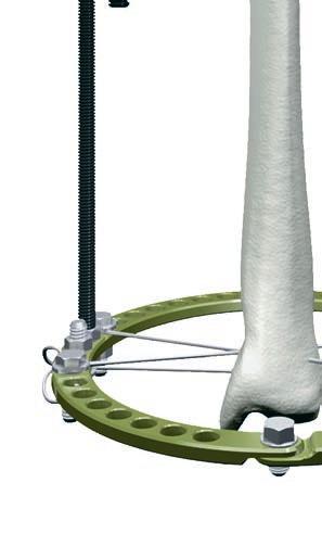
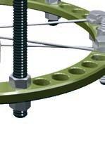
12 Frame Construction 1. Connect the two proximal rings Instrument Wrench B 8.0/11.0 mm Position the rings so that the most proximal ring is near the joint, but no closer than 20 mm, tissue condition and anatomy permitting. Position the next ring so that it is approximately mm proximal to the affected area, tissue condition and anatomy permitting. Align the connection bolts/joints of the half rings. Use threaded rods and nuts and the 8 mm/11 mm wrench to connect the rings. Typically, only three threaded rods are necessary between each pair of rings (4 rods should be used between pairs of 220 mm and 240 mm rings). See the Threaded Rod Spacing Chart for the recommended number of holes between threaded rods for each ring size. Be sure that the rings remain parallel to each other after they are connected. 2. Attach the third ring to the frame Position the third assembled ring approximately mm distal to the affected area, tissue condition and anatomy permitting. Align the connection bolts/ joints of the half rings with those of the previously connected rings and use threaded rods and nuts to connect this ring to them. For maximum stability, these threaded rods should be placed as close to equally between the threaded rods from the previous ring as possible (see picture). Be sure that the rings remain parallel to each other after they are connected. 11 DePuy Synthes The Distraction Osteogenesis Ring System Surgical Technique

13 3. Attach the fourth ring to the frame Instrument Wrench B 8.0/11.0 mm Position the fourth assembled ring near the distal joint, but no closer than 20 mm, tissue condition and anatomy permitting. Align the connection bolts/joints of the half rings with those of the previously connected rings and use threaded rods and nuts to connect this ring to them. For maximum stability, these threaded rods should be placed as close to equally between the threaded rods from the previous ring as possible (see picture). Be sure that the rings remain parallel to each other after they are connected. Note: During the construction of a frame, it may be helpful to insert a long threaded rod through all of the rings to help keep them aligned. Note: When holes in the rings do not line up properly (such as when different diameter rings are used), spherical washer couples, locking hinges or connecting plates may be used to connect the threaded rods to adjacent rings. The Distraction Osteogenesis Ring System Surgical Technique DePuy Synthes 11


14 Wire Insertion 1. Wire selection Select wires of appropriate size. The 1.8 mm and 2.0 mm wires are commonly used for adult patients while 1.5 mm wires are often used for small stature patients or in the hand and foot. Surgeon preference determines whether smooth wires or reduction wires are used. 2. Wire insertion Instruments Bending/Cutting Pliers An alcohol-soaked 4 4 sponge helps guide and cool the wire. Do not start the drill until the wire tip makes contact with the bone and stop drilling as soon as the tip protrudes from the far cortex of the bone. Insert wires perpendicular to the longitudinal axis of the affected limb, from the side with the most vulnerable anatomy. Anterior Tibial safe zones 11 DePuy Synthes The Distraction Osteogenesis Ring System Surgical Technique Posterior


15 Once the wire protrudes from the far cortex of the bone, tap it through the tissue on the far side. The flat side of the bending/cutting pliers may be used to tap the wire through the tissue. Once the wire is through, cut off the tip to prevent injury. Insert a smooth wire near the joint that is furthest from the injury site, perpendicular to the long axis of the bone and parallel to the joint. Insert the wire from the side of the limb with the most vulnerable anatomy. The wire should be no closer than 20 mm to the joint surface. Place the limb in longitudinal traction to aid in restoring length and reduction. Alternative Techniques Instruments Ratchet Wrench 11.0 mm Protection Sleeve, slotted, B 2.5 mm Hammer g Hammer 100 g The 2.5 mm split tissue protection sleeve may be used to hold the wire near the bone and aid in protecting the soft tissue. Use the flat side of the ratchet wrench or a hammer to tap the wire through the soft tissue. The Distraction Osteogenesis Ring System Surgical Technique DePuy Synthes 11
16 Wire Insertion 3. Position the frame on the wire Move the frame into the proper position along the wire. Position the half ring joints over anatomy features that would prevent wire insertion (there are fewer holes near the half ring joint). In the tibia, this places the connection bolts over the tibial crest or just lateral to it. Confirm that the frame sits so that the rings are perpendicular to the long axis of the bone. If the frame is not properly aligned with the bone, reposition the wire. 11 DePuy Synthes The Distraction Osteogenesis Ring System Surgical Technique


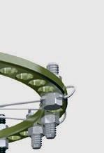
17 Wire Fixation 1. Attach the wire to the ring Instrument Wrench B 8.0/11.0 mm Use wire bolts to connect the wire to the ring. Choose either offset wire bolts or slotted wire bolts, depending on the position of the wire in relation to the holes in the ring. The wire should remain in a neutral position. Thread the bolts from below or above the ring, depending on where the wire sits. The wire should be between the bolt head and the ring. Use spacing washers between the bolt head and the ring or use wire posts if the wire does not contact the ring without bending. Do not bend wires to attach them to the ring (unless more advanced reduction techniques are being used). Fasten the bolts with nuts (standard or square). Tighten the nuts onto the bolts by hand; leave them loose enough to allow the rings to be easily repositioned on the wire. The Distraction Osteogenesis Ring System Surgical Technique DePuy Synthes 11
18 Insertion of Wire at the Opposite Bone End 1. Repeat wire insertion at the opposite end of the bone Instruments Ratchet Wrench 11.0 mm Wrench B 8.0/11.0 mm Insert a wire in the opposite end of the affected bone as was done at the first ring. Use wire bolts and nuts to attach this wire to the ring. 11 DePuy Synthes The Distraction Osteogenesis Ring System Surgical Technique


19 Wire Tensioning 1. Tighten one wire bolt and nut opposite from tensioning side Instrument Wrench B 8.0/11.0 mm Use two wrenches to tighten the nut and wire bolt opposite from where tension will be applied. When reduction wires are used, tighten the side with the stopper. Take care to keep the wire bolt head aligned, to prevent bending of the wire. Correct Incorrect The Distraction Osteogenesis Ring System Surgical Technique DePuy Synthes 11
 and the teeth on the front of the device seated securely against the ring, to ensure proper")

20 Wire Tensioning 2. Position tensioner on wire Instruments Wire Tightener a Standoff, hexagonal, length mm b From the tensioning side of the ring, pass the wire into the cannulation of the wire tightener. The wire tightener should be fully open (the black handle turned counterclockwise until it stops) and the teeth on the front of the device seated securely against the ring, to ensure proper tensioning of the wire. Center the wire bolt and nut between the teeth of the wire tightener. a Tighten offset bolt opposite wire tightener before tensioning. b Leave offset bolt loose when tensioning. Tighten after wire is tensioned. If other features prevent the teeth from sitting on the ring, place a standoff on the wire between the wire tightener and the ring. The threaded tip allows the standoff to be threaded onto the wire tightener. 11 DePuy Synthes The Distraction Osteogenesis Ring System Surgical Technique

21 3. Apply tension to the wire Instruments Wire Tightener Ratchet Wrench 11.0 mm Turn the wire tightener handle clockwise until the desired tension is attained. Typical wire tensions used are: When attached to a ring: 130 kg When attached to a ring on a young patient: 100 kg When positioned off of a ring: 50 kg 75 kg When positioned in the hand or foot: 50 kg 75 kg Optional technique A ratchet wrench can be used on the external hex nut at the back of the wire tightener to make turning the handle quicker. The Distraction Osteogenesis Ring System Surgical Technique DePuy Synthes 11

. After tensioning all the wires on a ring, retension them in the same sequence to maintain appropriate tension and obtain the best frame stability.")
22 Wire Tensioning 4. Tighten the wire bolt and nut Instruments Socket Wrench, slotted Ratchet Wrench 11.0 mm When the wire is fully tensioned, tighten the wire bolt near the wire tightener. A socket wrench can be used to hold the wire bolt head straight while a ratchet wrench is used to tighten the nut onto the bolt (or two ratchet wrenches may be used). Repeat this process for the remaining wire(s). After tensioning all the wires on a ring, retension them in the same sequence to maintain appropriate tension and obtain the best frame stability. This will help obtain the best frame stability with minimal deformation of the rings. After all wires have been tensioned, all nuts and bolts should be checked for tightness. Alternative Techniques: Use two tensioners from opposite sides to simultaneously tension two wires to maintain appropriate tension and obtain the best frame stability. Reduction wires are not always tensioned, as when they are used to reduce a fracture by transporting a segment over time. In this case, the end of the wire with the stopper is not secured to the ring. The opposite end may be held in a slotted threaded rod with two nuts and inserted through an eye bolt. The threaded rod can be pulled through the eye bolt using another nut, thereby moving the wire and the bone fragment that is held by the stopper. 22 DePuy Synthes The Distraction Osteogenesis Ring System Surgical Technique
 of wire past the wire bolt so that there is sufficient wire to grab if the wire needs tightening.")
23 5. Cut the ends of the wires Instrument Bending/Cutting Pliers After tensioning, cut the ends of the wires. Leave at least 60 mm (approximately 3 finger widths) of wire past the wire bolt so that there is sufficient wire to grab if the wire needs tightening. Curl the end of the wire using the bending/cutting pliers. 6. Tension the wire at the distal ring Repeat the tensioning process on the wire that is attached to the distal ring. The Distraction Osteogenesis Ring System Surgical Technique DePuy Synthes 22

24 Insertion of Additional Wires at First Ring 1. Insert two additional wires at first ring Place two more wires in the tibia at the first ring, perpendicular to the long axis of the bone. One wire should be above the ring and one below with the third wire inserted diagonally starting below the ring and ending above it on the opposite side. The third wire may also be inserted a few millimeters above or below the rings. These techniques help prevent the wires from hitting each other inside the bone or tissue. A wire may be weakened if it is contacted by the tip of another wire as it is inserted. Insert the wires so that they cross in the bone at as large an angle as the anatomy permits to prevent the bone from moving along the wires and provide maximum stability. Counter-opposing reduction (olive) wires can help stabilize this bone segment. 2. Attach the wires to the ring Instrument Wrench B 8.0/11.0 mm Use wire bolts and nuts to attach the wires to the ring, taking care not to bend the wires. 3. Tension the wires Tension, tighten and cut both wires as described on pages DePuy Synthes The Distraction Osteogenesis Ring System Surgical Technique

25 Insertion of Additional Wires at the Opposite Bone End 1. Repeat wire insertion at the opposite end of the bone Insert two more wires in the opposite end of the affected bone as was done at the first ring. Refer to step 1 on page Attach the wires to the ring Use wire bolts and nuts to attach the wires to the ring taking care not to bend the wires. 3. Tension the wires Tension, tighten and cut both wires as described on pages The Distraction Osteogenesis Ring System Surgical Technique DePuy Synthes 22
26 Insertion of Remaining Wires 1. Insert a wire in the proximal segment near the affected area Instrument Wrench B 8.0/11.0 mm Insert a wire at the ring that is mm proximal to the affected area. Connect the wire to the ring as described on page DePuy Synthes The Distraction Osteogenesis Ring System Surgical Technique

27 2. Insert a wire in the distal segment near the affected area Insert a wire at the ring that is mm distal to the affected area. Connect the wire to the ring as described on page 15. Alternative Technique Reduction wires may be used instead of smooth wires to aid in reduction. If reduction wires are used, they are placed with the stoppers on opposite sides of the bone to help hold the segments together. The Distraction Osteogenesis Ring System Surgical Technique DePuy Synthes 22
28 Insertion of Remaining Wires 3. Insert a second wire in the proximal segment near the affected area Insert a second wire at the ring that is just proximal to the fracture. Insert this wire on the opposite face of the ring from the first wire to prevent the wires from contacting and damaging each other. Insert this wire so that the angle between it and the previously inserted wire is as large as possible. 22 DePuy Synthes The Distraction Osteogenesis Ring System Surgical Technique
29 4. Insert a second wire in the distal segment near the affected area Insert a second wire at the ring that is just distal to the fracture. Insert this wire on the opposite face of the ring from the first wire, to prevent the wires from contacting and damaging each other. Insert this wire so that the angle between it and the previously inserted wire is as large as possible. The Distraction Osteogenesis Ring System Surgical Technique DePuy Synthes 22
30 Insertion of Remaining Wires 5. Attach and tension the remaining wires Instruments Wire Tightener Socket Wrench, slotted Ratchet Wrench 11.0 mm Wrench B 8.0/11.0 mm Bending/Cutting Pliers Attach the wires to the middle two rings with wire bolts as before and tension, tighten and cut them as described on pages Alternative Technique If reduction wires are used to help reduce a fragment, they are usually not tightened on the opposite side of the wire tightener until the fragment is pulled into the desired position by the wire tightener. Then the opposite wire bolt can be tightened and the wire tensioned. 6. Check the wires and connections Check all of the wires for tension and all connections for tightness. Note: Do not overtighten the screws. 7. Implant Removal Implants can be removed by using general surgical instruments. 22 DePuy Synthes The Distraction Osteogenesis Ring System Surgical Technique
31 Alternative Technique Precautions: Wire sites and pin sites should be cared for meticulously to avoid wire-tract and pin-tract infection. Wires and Schanz screws may be surrounded with antiseptic coated foam sponges in an effort to avoid infection. A wireand pin-site care procedure should be reviewed with the patient. To minimize the risk of pin track infection, the following points should be observed: a. Placement of Schanz screws taking anatomy into consideration (ligaments, nerves, arteries). b. Slow insertion and/or cooling, particularly in dense, hard bone to avoid heat necrosis. c. Release of skin tension at soft tissue entry point of implant. Use of Schanz screws Schanz screws may be used in the place of wires, or with wires (usually one Schanz screw in the place of one wire on a ring). The Distraction Osteogenesis Ring System contains a variety of clamps and bolts that can be used to attach Schanz screws to the frame. The Clamp, medium, clip-on, self-holding, ( ), the Combination Clamp, medium, clip-on, self-holding, ( ) and the Combination Clamp 8.0/11.0, clip-on,self-holding, ( ) can also be used to fix Schanz screws to threaded rods. Various drill sleeves are available that can be inserted in the clamps and bolts to aid in Schanz screw insertion. Alternative Technique Prebuilding a frame Prebuild the Distraction Osteogenesis Ring System frame and apply it in the operating room. Preoperative planning is required for construction of the appropriate frame. X-rays of 1:1 scale can be helpful when constructing such frames. The frame may also be constructed in the operating room off the patient. Once the frame is constructed, the connection bolts may be loosened on the rings to allow the frame to open up and be placed around the limb. Insert a wire in the tibia near the joint most distal to the affected area, no closer than 20 mm to the joint. Attach the frame to the wire using wire bolts and nuts. Insert a wire near the other joint, using the preconstructed frame as a reference. This wire should be no closer than 20 mm to that joint. Attach this wire to the frame with wire bolts and nuts. Tension both wires. Place additional wires at the proximal ring and distal ring. Insert wires at the middle two rings as described on pages using the rings as references when placing the wires. Tension and tighten all the wires. Note: For a detailed handling description of the Schanz screws, refer to the surgical technique Schanz Screws and Steinmann Pins (DSEM/TRM/0516/0677). Limb positioning Surgeons often use suction tubing and clamps to suspend the limb in the rings when applying the frame. Bumps or stands may also be used. The Distraction Osteogenesis Ring System Surgical Technique DePuy Synthes 22


32 Implants and Fixation Material Clamping Bolt for Schanz Screw Clamp, adjustable, for Schanz Screw Locking Hinge Clamping Bolt for Schanz Screws, for Post Universal Hinge * Wire B 1.5 mm, length 400 mm / Wire B 1.8 mm, length 400 mm * Wire B 2.0 mm, length 400 mm Smooth Wires Wire B 1.5 mm with Half Point Tip / Wire B 1.8 mm with Half Point Tip Wire B 2.0 mm with Half Point Tip * Also sterile available 33 DePuy Synthes The Distraction Osteogenesis Ring System Surgical Technique


33 * Reduction Wire B 1.5 mm, length 400 mm / / Reduction Wire B 1.8 mm, length 400 mm * Reduction Wire B 2.0 mm, length 400 mm Reduction Wires Reduction Wire B 1.5 mm with Half Point Tip / / / / Reduction Wire B 1.8 mm with Half Point Tip Reduction Wire B 2.0 mm with Half Point Tip Wire Bolt, slotted Wire Bolt, Offset Connecting Bolt Connecting Bolt, long Clamping Bolt, cannulated, for Schanz Screws, for Rings Clamping Bolt, cannulated, for Schanz Screws, for Post * Also sterile available The Distraction Osteogenesis Ring System Surgical Technique DePuy Synthes 33


34 Implants and Fixation Material Square Nut Nut, hexagonal Speed Nut Wire Post, short Wire Post, long Spacing Washer, 1.0 mm Spacing Washer, 2.0 mm Spacing Washer, 4.0 mm Spherical Washer, (Pair) Support, oblique 33 DePuy Synthes The Distraction Osteogenesis Ring System Surgical Technique


35 Eye Bolt Threaded Rod, slotted Art. No. Length (mm) Threaded Rod Art. No. Length (mm) * 400 Connecting Plate Art. No. Holes * * * 5 Standoff, hexagonal Art. No. Length (mm) * * 50 * Also sterile available The Distraction Osteogenesis Ring System Surgical Technique DePuy Synthes 33


36 Implants and Fixation Material Distractor for Angular Correction Angular Distractor Pivot for Angular Correction Protective Cap, for Schanz Screws and Steinmann Pins B 5.0 mm 33 DePuy Synthes The Distraction Osteogenesis Ring System Surgical Technique
 03.311.344 140 03.311.346 160 03.311.348 180 03.311.350 200 The Distraction Osteogenesis Ring System Surgical Technique DePuy Synthes 33")
37 Half-Ring, Titanium Alloy Art. No. Diameter (mm) Full Ring, Titanium Alloy Art. No. Diameter (mm) The Distraction Osteogenesis Ring System Surgical Technique DePuy Synthes 33
 03.311.373 130 03.311.375 150 03.311.376 160 03.311.378 180 03.")


38 Implants and Fixation Material 5/8 Ring, Titanium Alloy Art. No. Diameter (mm) Femoral Arch Plate, Titanium Alloy Art. No. Angle Diameter (mm) Linear Distractor Art. No. Length Distraction width (mm) (mm) Half-Ring, Carbon Fibre Art. No. Diameter (mm) DePuy Synthes The Distraction Osteogenesis Ring System Surgical Technique
 03.311.891 90 180 03.311.892 120 180 03.311.896 90 240 03.311.897 120 240 Foot Plate, Carbon Fibre Art. No.")

39 5/8 Ring, Carbon Fibre Art. No. Diameter (mm) Femoral Arch Plate, Carbon Fibre Art. No. Angle Diameter (mm) Foot Plate, Carbon Fibre Art. No. Description Diameter (mm) short short short short long long long long 180 The Distraction Osteogenesis Ring System Surgical Technique DePuy Synthes 33

40 Implants and Fixation Material Foot Plate, Titanium Alloy Art. No. Description Diameter (mm) short short short short short long long long DePuy Synthes The Distraction Osteogenesis Ring System Surgical Technique


41 Instruments Wire Tightener Socket Wrench, slotted Ratchet Wrench 11.0 mm Protection Sleeve, slotted, B 2.5 mm Protection Sleeve, slotted, B 5.0 mm Wrench B 8.0/11.0 mm Back-up Wire Tightener The Distraction Osteogenesis Ring System Surgical Technique DePuy Synthes 33


42 Instruments Drill Bit B 3.5 mm, length 195/170 mm, 2-flute, for Quick Coupling / / Bending/Cutting Pliers Adapter for SELDRILL Schanz Screw B 5.0 mm Universal Chuck, small, with T-Handle Trocar B 3.5 mm, long Handle for Drill Sleeve 44 DePuy Synthes The Distraction Osteogenesis Ring System Surgical Technique

43 Drill Sleeve 5.0/3.5, long Drill Sleeve 6.0/5.0, long, with thread Also available Wrench B 8.0/11.0 mm, for Patient Drive Adaptors with quick coupling Schanz Screw B 4.0 mm Schanz Screw B 4.5 mm Schanz Screw B 5.0 mm Schanz Screw B 6.0 mm Hammers g g g g The Distraction Osteogenesis Ring System Surgical Technique DePuy Synthes 44
44 Set ( ) Vario Case Vario Case for Distraction Osteogenesis (Implants and Instruments) Vario Case for Distraction Osteogenesis (standard ring components) Vario Case for Distraction Osteogenesis (optional ring components) Instruments Art. No. Description Units Wire Tightener Socket Wrench, slotted Ratchet Wrench 11.0 mm Protection Sleeve, slotted, B 2.5 mm Protection Sleeve, slotted, B 5.0 mm Wrench B 8.0/11.0 mm Back-up Wire Tightener Drill Bit B 3.5 mm, length 195/170 mm, 2-flute, for Quick Coupling Bending/Cutting Pliers Adapter for SELDRILL Schanz Screw B 5.0 mm Universal Chuck, small, with T-Handle Trocar B 3.5 mm, long Handle for Drill Sleeve Drill Sleeve 5.0/3.5, long Drill Sleeve 6.0/5.0, long, with thread 1 44 DePuy Synthes The Distraction Osteogenesis Ring System Surgical Technique
45 Implants and Fixation Material Art. No. Description Units Washer B 7.0/3.6 mm, for Screws B 2.7 to 4.0 mm, Stainless Steel SELDRILL Schanz Screw B 5.0 mm, length 175/60 mm, Stainless Steel SELDRILL Schanz Screw B 5.0 mm, length 175/60 mm, Stainless Steel SELDRILL Schanz Screw B 5.0 mm, length 200/80 mm, Stainless Steel Clamping Bolt for Schanz Screw Clamp, adjustable, for Schanz Screw Locking Hinge Wire B 1.8 mm, length 400 mm Reduction Wire B 1.8 mm, length 400 mm Wire Bolt, slotted Wire Bolt, Offset Connecting Bolt Square Nut Nut, hexagonal, pack of Wire Post, short Wire Post, long Spacing Washer, 1.0 mm Spacing Washer, 2.0 mm Spacing Washer, 4.0 mm Spherical Washer (Pair) Support, oblique Eye Bolt 2 Threaded Rod Art. No. Length (mm) Units , slotted , slotted , slotted Connecting Plate, 3 holes Connecting Plate, 4 holes Standoff, hexagonal, length 30 mm Standoff, hexagonal, length 40 mm Distractor for Angular Correction Angular Distractor Pivot for Angular Correction Protective Cap, for Schanz Screws and Steinmann Pins B 5.0 mm pack of 10 Note: For a detailed product information of the Schanz screws, refer to the surgical technique Schanz Screws and Steinmann Pins (DSEM/TRM/0516/0677). The Distraction Osteogenesis Ring System Surgical Technique DePuy Synthes 44
46 Also Available Wrench B 8.0/11.0 mm, for Patient Wire, *half spade tip Art. No. Diameter Length Description (mm) (mm) * * * Reduction Wire, *half spade tip Art. No. Diameter Length Description (mm) (mm) * * * Half-Ring, Titanium Alloy Art. No. Diameter (mm) Threaded Rod, length 400 mm Connecting Plate, 2 holes Connecting Plate, 5 holes Standoff, hexagonal, length 20 mm Standoff, hexagonal, length 50 mm 44 DePuy Synthes The Distraction Osteogenesis Ring System Surgical Technique
47 Full Ring, Titanium Alloy Art. No. Diameter (mm) /8 Ring, Titanium Alloy Art. No. Diameter (mm) Half-Ring, Carbon Fibre Art. No. Diameter (mm) Femoral Arch Plate, Titanium Alloy Art. No. Angle Diameter (mm) Linear Distractor Art. No. Length mm Distraction width (mm) The Distraction Osteogenesis Ring System Surgical Technique DePuy Synthes 44
48 Also available Full Ring, Carbon Fibre Art. No. Diameter (mm) /8 Ring, Carbon Fibre Art. No. Diameter (mm) Femoral Arch Plate, Carbon Fibre Art. No. Angle Diameter (mm) Foot Plate, Carbon Fibre Art. No. Description Diameter (mm) short short short short long long long long DePuy Synthes The Distraction Osteogenesis Ring System Surgical Technique
49 Clamps Combination Clamp, medium, clip-on, self-holding Clamp, medium, clip-on, self-holding Combination Clamp 8.0/11.0, clip-on, self-holding Drive Adaptors with quick coupling Schanz Screw B 4.0 mm Schanz Screw B 4.5 mm Schanz Screw B 6.0 mm Hammers g g g g Vario Case Additional Components Rack for Offset Bolts Rack for Slotted Bolts Rack for Connection Bolts The Distraction Osteogenesis Ring System Surgical Technique DePuy Synthes 44
50 Also available Instruments Bending/Cutting Pliers Ring-to-Rod Clamp, for Hybrid Ring Fixator Wire/Pin-to-Ring Clamp Full Ring, internal diameter 205 mm Three-quarter Ring, internal diameter 205 mm Double Clamp with Angled Piece Full Ring, internal diameter 115 mm Three-quarter Ring, internal diameter 115 mm Three-quarter Ring, internal diameter 140 mm Full Ring, internal diameter 165 mm Three-quarter Ring, internal diameter 165 mm Quarter Ring, internal diameter 165 mm Wire Tightener Protection Sleeve, slotted, for Wires B 1.8 to 2.0 mm Protection Sleeve, slotted, for Schanz Screws up to B 5.0 mm 44 DePuy Synthes The Distraction Osteogenesis Ring System Surgical Technique
51
52 Synthes GmbH Eimattstrasse 3 Not all products are currently available in all markets Oberdorf Switzerland This publication is not intended for distribution in the USA. Tel: Fax: All surgical techniques are available as PDF files at DePuy Synthes Trauma, a division of Synthes GmbH All rights reserved DSEM/TRM/0714/0136b(3) 04/18
Technique Guide. The Distraction Osteogenesis Ring System. Nonarticular tibia frame.
 Technique Guide The Distraction Osteogenesis Ring System. Nonarticular tibia frame. Table of Contents Introduction The Distraction Osteogenesis Ring System 2 AO Principles 4 Indications 5 Surgical Technique
Technique Guide. The Distraction Osteogenesis Ring System. Intra-articular distal tibia frame.
 Technique Guide The Distraction Osteogenesis Ring System. Intra-articular distal tibia frame. Table of Contents Introduction The Distraction Osteogenesis Ring System 2 MRI Information 4 AO Principles 5
Femur Frame. The Distraction Osteogenesis Ring System
 Femur Frame The Distraction Osteogenesis Ring System Surgical Technique Table of Contents Introduction The Distraction Osteogenesis Ring System 2 MRI Information 4 AO Principles 5 Indications 6 Surgical
The Distraction Osteogenesis Ring System
 Nonarticular Tibia Frame The Distraction Osteogenesis Ring System Surgical Technique Table of Contents Introduction The Distraction Osteogenesis Ring System 2 MRI Information 4 AO Principles 5 Indications
The Distraction Osteogenesis Ring System
 Intra-articular Distal Tibia Frame The Distraction Osteogenesis Ring System Surgical Technique Table of Contents Introduction The Distraction Osteogenesis Ring System 2 MRI Information 4 AO Principles
External Distal Radius Fixator. Supplement to the 8 mm rod fixator system
 External Distal Radius Fixator. Supplement to the 8 mm rod fixator system Surgical technique This publication is not intended for distribution in the USA. Instruments and implants approved by the AO Foundation
LCP Low Bend Medial Distal Tibia Plates 3.5 mm. Anatomic plates with low profile head for intra- and extraarticular fractures.
 LCP Low Bend Medial Distal Tibia Plates 3.5 mm. Anatomic plates with low profile head for intra- and extraarticular fractures. Surgical Technique This publication is not intended for distribution in the
MEFiSTO. Monolateral External Fixation System for Trauma and Orthopaedics.
 MEFiSTO. Monolateral External Fixation System for Trauma and Orthopaedics. Surgical Technique This publication is not intended for distribution in the USA. Instruments and implants approved by the AO Foundation.
For Small-Statured Adults and Pediatric Patients. Medium External Fixator Basic Modular Frame
 For Small-Statured Adults and Pediatric Patients Medium External Fixator Basic Modular Frame Surgical Technique MRI Information DePuy Synthes Medium External Fixation devices are labeled MR Conditional
Medium External Fixator Humeral Shaft Frame. Modular frame for upper extremity use.
 Medium External Fixator Humeral Shaft Frame. Modular frame for upper extremity use. Technique Guide Part of the Medium External Fixation System MRI Information Synthes Medium External Fixation devices
Medium External Fixator Pediatric Femoral Shaft Frame. Using medium multi-pin clamps.
 Medium External Fixator Pediatric Femoral Shaft Frame. Using medium multi-pin clamps. Technique Guide Part of the Medium External Fixation System MRI Information Synthes Medium External Fixation devices
MEFiSTO. Monolateral External Fixation System for Trauma and Orthopaedics.
 MEFiSTO. Monolateral External Fixation System for Trauma and Orthopaedics. Surgical Technique This publication is not intended for distribution in the USA. Instruments and implants approved by the AO Foundation.
LCP Metaphyseal Plates. For extra-articular fractures.
 LCP Metaphyseal Plates. For extra-articular fractures. Surgical Technique This publication is not intended for distribution in the USA. Instruments and implants approved by the AO Foundation. Image intensifier
LCP DISTAL TIBIA PLATE
 LCP DISTAL TIBIA PLATE Instruments and implants approved by the AO Foundation. This publication is not intended for distribution in the USA. SURGICAL TECHNIQUE Image intensifier control This description
Mandible External Fixator II. Provides treatment for fractures of the maxillofacial area.
 Mandible External Fixator II. Provides treatment for fractures of the maxillofacial area. Technique Guide This publication is not intended for distribution in the USA. Instruments and implants approved
2.4 mm Variable Angle LCP Volar Extra-Articular Distal Radius System. For fragment-specific fracture fixation with variable angle locking technology.
 2.4 mm Variable Angle LCP Volar Extra-Articular Distal Radius System. For fragment-specific fracture fixation with variable angle locking technology. Surgical Technique This publication is not intended
Large External Fixator Modular Knee Bridge
 Using Multi-pin Clamps Large External Fixator Modular Knee Bridge Surgical Technique Large External Fixator Modular Knee Bridge DePuy Synthes Large External Fixation devices are labeled MR Conditional
LCP Proximal Radius Plates 2.4. Plates for radial head rim and for radial head neck address individual fracture patterns of the proximal radius.
 LCP Proximal Radius Plates 2.4. Plates for radial head rim and for radial head neck address individual fracture patterns of the proximal radius. Surgical Technique This publication is not intended for
Mandible External Fixator II
 Provides treatment for fractures of the mandible Mandible External Fixator II Surgical Technique Image intensifier control This description alone does not provide sufficient background for direct use of
Surgical Technique. Computer Assisted Circular Ring Fixation System for the Treatment of Limb Deformity Correction
 Computer Assisted Circular Ring Fixation System for the Treatment of Limb Deformity Correction Surgical Technique This publication is not intended for distribution in the USA. Image intensifier control
PROXIMAL FEMORAL NAIL REMOVAL SET
 PROXIMAL FEMORAL NAIL REMOVAL SET for PFN, TFN and PFNA/PFNA-II Instruments and Implants approved by the AO Foundation. This publication is not intended for distribution in the USA. SURGICAL TECHNIQUE
The Calcaneal Plate. The Synthes non-locking solution for the Calcaneus.
 The Calcaneal Plate. The Synthes non-locking solution for the Calcaneus. Surgical Technique This publication is not intended for distribution in the USA. Instruments and implants approved by the AO Foundation.
Mini External Fixator.
 Mini External Fixator. Assembly and Surgical Technique This publication is not intended for distribution in the USA. Instruments and implants approved by the AO Foundation. Image intensifier control Warning
OBSOLETED. LCP Medial Distal Tibia Plate, without Tab. The Low Profile Anatomic Fixation System with Angular Stability and Optimal Screw Orientation.
 LCP Medial Distal Tibia Plate, without Tab. The Low Profile Anatomic Fixation System with Angular Stability and Optimal Screw Orientation. Surgical Technique LCP Small Fragment System This publication
Mandible External Fixator II
 Provides Treatment for Fractures of the Mandible Mandible External Fixator II Surgical Technique Table of Contents Introduction Mandible External Fixator II 2 AO Principles 4 Indications 5 MRI Information
Low-Profile Wrist Fixator. For stabilization of fractures of the distal radius.
 Low-Profile Wrist Fixator. For stabilization of fractures of the distal radius. Technique Guide Part of the External Fixation System Low-Profile Wrist Fixator Indications Intended for stabilization of
Medium External Fixator Delta Frame Ankle Bridge
 For Small-Statured Adults Medium External Fixator Delta Frame Ankle Bridge Surgical Technique MRI Information DePuy Synthes Medium External Fixation devices are labeled MR Conditional according to the
LCP Distal Fibula Plates. Part of the Synthes locking compression plate (LCP) system.
 system.") LCP Distal Fibula Plates. Part of the Synthes locking compression plate (LCP) system. Surgical Technique This publication is not intended for distribution in the USA. Instruments and implants approved
LCP Distal Fibula Plates. Part of the Synthes locking compression plate (LCP) system. Surgical Technique This publication is not intended for distribution in the USA. Instruments and implants approved
Large External Fixator Traveling Traction
 Used to Correct Angular Deformity Large External Fixator Traveling Traction Surgical Technique Large External Fixator Traveling Traction DePuy Synthes Large External Fixation devices are labeled MR Conditional
LCP Proximal Tibial Plate 4.5/5.0 with Periarticular Aiming Arm Instruments
 LCP Proximal Tibial Plate 4.5/5.0 with Periarticular Aiming Arm Instruments Surgical Technique This publication is not intended for distribution in the USA. Instruments and implants approved by the AO
Cannulated Pediatric Osteotomy System (CAPOS). A single system of osteotomy blade plates and cannulated instrumentation.
. A single system of osteotomy blade plates and cannulated instrumentation.") Cannulated Pediatric Osteotomy System (CAPOS). A single system of osteotomy blade plates and cannulated instrumentation. Surgical Technique This publication is not intended for distribution in the USA.
Cannulated Pediatric Osteotomy System (CAPOS). A single system of osteotomy blade plates and cannulated instrumentation. Surgical Technique This publication is not intended for distribution in the USA.
Mini External Fixator
 Stabilize the Phalanges and Metacarpals Mini External Fixator Surgical Technique Table of Contents Introduction Mini External Fixator 2 Indications 4 Surgical Technique Technique Overview 5 Product Information
LCP Proximal Radius Plates 2.4. Plates for radial head rim and for radial head neck address individual fracture patterns of the proximal radius.
 LCP Proximal Radius Plates 2.4. Plates for radial head rim and for radial head neck address individual fracture patterns of the proximal radius. Surgical Technique This publication is not intended for
Femoral Neck System. Surgical Technique
 Femoral Neck System Surgical Technique Image intensifier control This description alone does not provide sufficient background for direct use of DePuy Synthes products. Instruction by a surgeon experienced
Monolateral External Fixation System for Trauma and Orthopaedics
 MEFiSTO Monolateral External Fixation System for Trauma and Orthopaedics Surgical Technique Original Instruments and Implants of the Association for the Study of Internal Fixation AO/ASIF MEFiSTO Table
VA LOCKING CALCANEAL PLATES 2.7
 VA LOCKING CALCANEAL PLATES 2.7 Instruments and Implants approved by the AO Foundation. This publication is not intended for distribution in the USA. SURGICAL TECHNIQUE Image intensifier control Warning
Hybrid Ring Fixator. Rapid treatment in complex, periarticular tibial fractures.
 Hybrid Ring Fixator. Rapid treatment in complex, periarticular tibial fractures. Surgical Technique This publication is not intended for distribution in the USA. Instruments and implants approved by the
LCP Condylar Plate 4.5/5.0. Part of the LCP Periarticular Plating System.
 LCP Condylar Plate 4.5/5.0. Part of the LCP Periarticular Plating System. Surgical Technique This publication is not intended for distribution in the USA. Instruments and implants approved by the AO Foundation.
LCP Medial Proximal Tibial Plate 3.5. Part of the Synthes small fragment Locking Compression Plate (LCP) system.
 system.") LCP Medial Proximal Tibial Plate 3.5. Part of the Synthes small fragment Locking Compression Plate (LCP) system. Surgical Technique This publication is not intended for distribution in the USA. Instruments
LCP Medial Proximal Tibial Plate 3.5. Part of the Synthes small fragment Locking Compression Plate (LCP) system. Surgical Technique This publication is not intended for distribution in the USA. Instruments
ANGLED BLADE PLATES FOR ADULTS
 ANGLED BLADE PLATES FOR ADULTS Instruments and implants approved by the AO Foundation. This publication is not intended for distribution in the USA. SURGICAL TECHNIQUE Image intensifier control This description
Large External Fixator Delta Frame Ankle Bridge. Using pin clamps with outrigger posts.
 Large External Fixator Delta Frame Ankle Bridge. Using pin clamps with outrigger posts. Technique Guide Part of the Large External Fixation System Large External Fixator Delta Frame Ankle Bridge Technique
Distal Radius Plate 2.4/2.7 dorsal and volar
 Distal Radius Plate 2.4/2.7 dorsal and volar Surgical Technique This publication is not intended for distribution in the USA. Instruments and implants approved by the AO Foundation. Distal Radius Plate
Large External Fixator Modular Knee Bridge. Using multi-pin clamps.
 Large External Fixator Modular Knee Bridge. Using multi-pin clamps. Technique Guide Part of the Large External Fixation System Large External Fixator Modular Knee Bridge Technique Overview Insert Schanz
3.5 mm LCP Low Bend Medial Distal Tibia Plate Aiming Instruments
 Part of the 3.5 mm LCP 3.5 mm LCP Low Bend Medial Distal Tibia Plate Aiming Instruments Surgical Technique TABLE OF CONTENTS INTRODUCTION 3.5 mm LCP Low Bend Medial Distal Tibia Plate 2 Aiming Instruments
Technique Guide. Compact 2.0 LOCK Mandible. The locking system for the mandible.
 Technique Guide Compact 2.0 LOCK Mandible. The locking system for the mandible. Table of Contents Introduction Compact 2.0 LOCK Mandible 2 AO Principles 4 Indications and Contraindications 5 Surgical
LCP Superior Anterior Clavicle Plate. The anatomically precontoured fixation system with angular stability for clavicle shaft and lateral clavicle.
 LCP Superior Anterior Clavicle Plate. The anatomically precontoured fixation system with angular stability for clavicle shaft and lateral clavicle. Surgical Technique This publication is not intended for
LCP Distal Fibula Plates. Part of the Synthes locking compression plate (LCP) system.
 system.") LCP Distal Fibula Plates. Part of the Synthes locking compression plate (LCP) system. Surgical Technique This publication is not intended for distribution in the USA. Instruments and implants approved
LCP Distal Fibula Plates. Part of the Synthes locking compression plate (LCP) system. Surgical Technique This publication is not intended for distribution in the USA. Instruments and implants approved
LCP Medial Proximal Tibial Plate 3.5. Part of the Synthes small fragment Locking Compression Plate (LCP) system.
 system.") LCP Medial Proximal Tibial Plate 3.5. Part of the Synthes small fragment Locking Compression Plate (LCP) system. Technique Guide This publication is not intended for distribution in the USA. Instruments
LCP Medial Proximal Tibial Plate 3.5. Part of the Synthes small fragment Locking Compression Plate (LCP) system. Technique Guide This publication is not intended for distribution in the USA. Instruments
Part of the DePuy Synthes Locking Compression Plate (LCP ) System. 3.5 mm LCP Medial Proximal Tibia Plates
 System. 3.5 mm LCP Medial Proximal Tibia Plates") Part of the DePuy Synthes Locking Compression Plate (LCP ) System 3.5 mm LCP Medial Proximal Tibia Plates Surgical Technique Table of Contents Introduction 3.5 mm LCP Medial Proximal Tibia Plates 2 AO
Part of the DePuy Synthes Locking Compression Plate (LCP ) System 3.5 mm LCP Medial Proximal Tibia Plates Surgical Technique Table of Contents Introduction 3.5 mm LCP Medial Proximal Tibia Plates 2 AO
Cannulated Pediatric Osteotomy System (CAPOS). A single system of osteotomy blade plates and cannulated instrumentation.
. A single system of osteotomy blade plates and cannulated instrumentation.") Cannulated Pediatric Osteotomy System (CAPOS). A single system of osteotomy blade plates and cannulated instrumentation. Surgical Technique This publication is not intended for distribution in the USA.
Cannulated Pediatric Osteotomy System (CAPOS). A single system of osteotomy blade plates and cannulated instrumentation. Surgical Technique This publication is not intended for distribution in the USA.
Elbow Hinge Fixator. Guided Flexion/Extension for Unstable Elbow Fractures.
 Elbow Hinge Fixator. Guided Flexion/Extension for Unstable Elbow Fractures. Surgical Technique MR Safe Radiolucent Table of Contents System Description 3 Indications and Contraindications 4 Fixation Components
3.5 mm LCP Olecranon Plates
 Part of the DePuy Synthes Locking Compression Plate (LCP ) System 3.5 mm LCP Olecranon Plates Surgical Technique Table of Contents Introduction 3.5 mm LCP Olecranon Plates 2 AO Principles 3 Indications
Large External Fixator Delta Frame Ankle Bridge. For staged fixation of the distal tibia.
 Large External Fixator Delta Frame Ankle Bridge. For staged fixation of the distal tibia. Technique Guide Part of the Large External Fixation System Large External Fixator Delta Frame Ankle Bridge Technique
Cannulated Angled Blade Plate 3.5 and 4.5, 90.
 Cannulated Angled Blade Plate 3.5 and 4.5, 90. Technique Guide This publication is not intended for distribution in the USA. Instruments and implants approved by the AO Foundation. Table of Contents Introduction
4.5 mm LCP Medial Proximal Tibia Plates
 Part of the DePuy Synthes LCP Periarticular Plating System 4.5 mm LCP Medial Proximal Tibia Plates Surgical Technique Table of Contents Introduction 4.5 mm LCP Medial Proximal Tibia Plates 2 AO Principles
VA-LCP Anterior Clavicle Plate. The anatomically precontoured fixation system with angular stability for clavicle shaft and lateral clavicle.
 VA-LCP Anterior Clavicle Plate. The anatomically precontoured fixation system with angular stability for clavicle shaft and lateral clavicle. Surgical Technique This publication is not intended for distribution
3.5 mm LCP Extra-articular Distal Humerus Plate
 Part of the DePuy Synthes Locking Compression Plate (LCP ) System 3.5 mm LCP Extra-articular Distal Humerus Plate Surgical Technique Table of Contents Introduction 3.5 mm LCP Extra-articular Distal Humerus
TELEFIX SURGICAL TECHNIQUE. Implant system for the anterior stabilization of the thoracolumbar spine
 TELEFIX Implant system for the anterior stabilization of the thoracolumbar spine Instruments and implants approved by the AO Foundation. This publication is not intended for distribution in the USA. SURGICAL
Long Volar Plates for Diaphyseal-Metaphyseal Radius Fractures LCP. Dia-Meta Volar Distal Radius Plates. Surgical Technique
 Long Volar Plates for Diaphyseal-Metaphyseal Radius Fractures LCP Dia-Meta Volar Distal Radius Plates Surgical Technique Table of Contents Introduction LCP Dia-Meta Volar Distal Radius Plates 2 AO Principles
Cannulated Pediatric Osteotomy System (CAPOS)
") A Single System of Osteotomy Blade Plates and Cannulated Instrumentation Cannulated Pediatric Osteotomy System (CAPOS) Surgical Technique Table of Contents Introduction Cannulated Pediatric Osteotomy System
A Single System of Osteotomy Blade Plates and Cannulated Instrumentation Cannulated Pediatric Osteotomy System (CAPOS) Surgical Technique Table of Contents Introduction Cannulated Pediatric Osteotomy System
Surgical Technique. This publication is not intended for distribution in the USA. Instruments and implants approved by the AO Foundation.
 LCP Extra-articular Distal Humerus Plate. The anatomically shaped and angular stable fixation system for extraarticular fractures of the distal humerus. Surgical Technique This publication is not intended
LCP Superior Clavicle Plate. The anatomically precontoured fixation system with angular stability for clavicle shaft and lateral clavicle.
 LCP Superior Clavicle Plate. The anatomically precontoured fixation system with angular stability for clavicle shaft and lateral clavicle. Surgical Technique This publication is not intended for distribution
Collinear Reduction Clamp
 For minimally invasive fracture reduction Collinear Reduction Clamp Surgical Technique Image intensifier control This description alone does not provide sufficient background for direct use of DePuy Synthes
LCP Periarticular Proximal Humerus Plate 3.5. The anatomic fixation system with anterolateral shaft placement.
 LCP Periarticular Proximal Humerus Plate 3.5. The anatomic fixation system with anterolateral shaft placement. Surgical Technique This publication is not intended for distribution in the USA. Instruments
LCP Ulna Osteotomy System 2.7. Low profile angular stable fixation for ulna shortening osteotomies.
 LCP Ulna Osteotomy System 2.7. Low profile angular stable fixation for ulna shortening osteotomies. Surgical Technique This publication is not intended for distribution in the USA. Instruments and implants
LCP Medial Proximal Tibial Plate 4.5/5.0. Part of the Synthes LCP periarticular plating system.
 LCP Medial Proximal Tibial Plate 4.5/5.0. Part of the Synthes LCP periarticular plating system. Technique Guide This publication is not intended for distribution in the USA. Instruments and implants approved
For the Treatment of Wrist Fractures. Small External Fixator Nonspanning Wrist Frame
 For the Treatment of Wrist Fractures Small External Fixator Nonspanning Wrist Frame Surgical Technique Small External Fixator Nonspanning Wrist Frame DePuy Synthes Small External Fixation devices are labeled
Periarticular Aiming Arm Instruments for LCP Condylar Plate 4.5/5.0. Part of the LCP Periarticular Aiming Arm Instrument System (large).
.") Periarticular Aiming Arm Instruments for LCP Condylar Plate 4.5/5.0. Part of the LCP Periarticular Aiming Arm Instrument System (large). Surgical Technique This publication is not intended for distribution
Periarticular Aiming Arm Instruments for LCP Condylar Plate 4.5/5.0. Part of the LCP Periarticular Aiming Arm Instrument System (large). Surgical Technique This publication is not intended for distribution
Orthodontic Bone Anchor (OBA) System
 System") Skeletal implants for the orthodontic movement of the teeth Orthodontic Bone Anchor (OBA) System Surgical Technique Image intensifier control This description alone does not provide sufficient background
Skeletal implants for the orthodontic movement of the teeth Orthodontic Bone Anchor (OBA) System Surgical Technique Image intensifier control This description alone does not provide sufficient background
Low Bend Distal Tibia Plates
 Part of the DePuy Synthes Locking Compression Plate (LCP ) System 3.5 mm LCP Low Bend Medial Distal Tibia Plates Surgical Technique Table of Contents Introduction 3.5 mm LCP Low Bend Medial Distal Tibia
Cannulated Pediatric Osteotomy System (CAPOS). A single system of osteotomy blade plates and cannulated instrumentation.
. A single system of osteotomy blade plates and cannulated instrumentation.") Cannulated Pediatric Osteotomy System (CAPOS). A single system of osteotomy blade plates and cannulated instrumentation. Technique Guide This publication is not intended for distribution in the USA. Instruments
Cannulated Pediatric Osteotomy System (CAPOS). A single system of osteotomy blade plates and cannulated instrumentation. Technique Guide This publication is not intended for distribution in the USA. Instruments
LCP Proximal Femoral Hook Plate 4.5/5.0. Part of the LCP Periarticular Plating System.
 LCP Proximal Femoral Hook Plate 4.5/5.0. Part of the LCP Periarticular Plating System. Surgical Technique This publication is not intended for distribution in the USA. Instruments and implants approved
Olecranon Osteotomy Nail. For simple fractures and osteotomies of the olecranon.
 Olecranon Osteotomy Nail. For simple fractures and osteotomies of the olecranon. Technique Guide Discontinued June 2016; AVAILABLE FOR IMPLANT REMOVAL PURPOSES ONLY DSEM/TRM/0517/0843 Table of Contents
VECTRA-T SURGICAL TECHNIQUE. The Translational Anterior Cervical Palate System. This publication is not intended for distribution in the USA.
 VECTRA-T The Translational Anterior Cervical Palate System This publication is not intended for distribution in the USA. SURGICAL TECHNIQUE Image intensifier control This description alone does not provide
3.0/3.5/4.0/4.5/6.5/7.0/7.3. Cannulated Screws. Surgical Technique
 3.0/3.5/4.0/4.5/6.5/7.0/7.3 Cannulated Screws Surgical Technique Image intensifier control This description alone does not provide sufficient background for direct use of DePuy Synthes products. Instruction
LCP Condylar Plate 4.5/5.0. Part of the LCP Periarticular Plating System.
 LCP Condylar Plate 4.5/5.0. Part of the LCP Periarticular Plating System. Surgical Technique This publication is not intended for distribution in the USA. Instruments and implants approved by the AO Foundation.
Large Distractor Femur
 Fracture Reduction and Provisional Stabilization Large Distractor Femur Surgical Technique Table of Contents Introduction Standard Femoral Distraction 2 Large Distractor System 4 Surgical Technique Prepare
ARCH Laminoplasty System. Dedicated System for Open-door Laminoplasty.
 ARCH Laminoplasty System. Dedicated System for Open-door Laminoplasty. Surgical Technique This publication is not intended for distribution in the USA. Instruments and implants approved by the AO Foundation.
PHILOS and PHILOS Long. The anatomic fixation system for the proximal humerus.
 PHILOS and PHILOS Long. The anatomic fixation system for the proximal humerus. Surgical Technique This publication is not intended for distribution in the USA. Instruments and implants approved by the
VA LCP MEDIAL COLUMN FUSION PLATES 3.5
 VA LCP MEDIAL COLUMN FUSION PLATES 3.5 Instruments and Implants approved by the AO Foundation. This publication is not intended for distribution in the USA. SURGICAL TECHNIQUE Image intensifier control
2.7 mm/3.5 mm LCP Distal Fibula Plate
 Part of the DePuy Synthes Locking Compression Plate (LCP ) System 2.7 mm/3.5 mm LCP Distal Fibula Plate Surgical Technique Table of Contents Introduction 2.7 mm/3.5 mm LCP Distal Fibula Plates 2 AO Principles
VA-LCP Anterior Clavicle Plate. The anatomically precontoured fixation system with angular stability for clavicle shaft and lateral clavicle.
 Technique Guide VA-LCP Anterior Clavicle Plate. The anatomically precontoured fixation system with angular stability for clavicle shaft and lateral clavicle. Table of Contents Introduction VA-LCP Anterior
VA-LCP Olecranon Plates 2.7/3.5. The fracture-specific low-profile fixation system with variable angle locking technology.
 VA-LCP Olecranon Plates 2.7/3.5. The fracture-specific low-profile fixation system with variable angle locking technology. Surgical Technique This publication is not intended for distribution in the USA.
Large External Fixator Pelvic Frame
 For Treatment of Unstable Pelvic Ring Injuries Large External Fixator Pelvic Frame Surgical Technique LARGE EXTERNAL FIXATOR PELVIC FRAME DePuy Synthes Companies of Johnson & Johnson Large External Fixation
TSLP Thoracolumbar Spine Locking Plate
 Anterior thoracolumbar spine locking plate TSLP Thoracolumbar Spine Locking Plate Surgical Technique Image intensifier control This description alone does not provide sufficient background for direct use
Button Plate. Reinforcement for transosseous fixations.
 Button Plate. Reinforcement for transosseous fixations. Product Information This publication is not intended for distribution in the USA. Instruments and implants approved by the AO Foundation. Image intensifier
Periarticular Aiming Arm Instruments for LCP Proximal Tibial Plate 4.5/5.0. Part of the LCP Periarticular Aiming Arm Instrument System (large).
.") Technique Guide Periarticular Aiming Arm Instruments for LCP Proximal Tibial Plate 4.5/5.0. Part of the LCP Periarticular Aiming Arm Instrument System (large). Image intensifier control Warning This description
Technique Guide Periarticular Aiming Arm Instruments for LCP Proximal Tibial Plate 4.5/5.0. Part of the LCP Periarticular Aiming Arm Instrument System (large). Image intensifier control Warning This description
LCP Superior Clavicle Plate. The anatomically precontoured fixation system with angular stability for clavicle shaft and lateral clavicle.
 Technique Guide LCP Superior Clavicle Plate. The anatomically precontoured fixation system with angular stability for clavicle shaft and lateral clavicle. Table of Contents Introduction LCP Superior Clavicle
Technique Guide. LCP Distal Fibula Plates. Part of the Synthes locking compression plate (LCP) system.
 system.") Technique Guide LCP Distal Fibula Plates. Part of the Synthes locking compression plate (LCP) system. Table of Contents Introduction LCP Distal Fibula Plates 2 AO Principles 4 Indications 5 Surgical Technique
Technique Guide LCP Distal Fibula Plates. Part of the Synthes locking compression plate (LCP) system. Table of Contents Introduction LCP Distal Fibula Plates 2 AO Principles 4 Indications 5 Surgical Technique
3.5 mm LCP Hook Plate
 Part of the DePuy Synthes Locking Compression Plate (LCP ) System 3.5 mm LCP Hook Plate Surgical Technique Table of Contents Introduction 3.5 mm LCP Hook Plate 2 AO Principles 4 Indications 5 Clinical
LCP Medial Distal Tibia Plate, without Tab. The Low Profile Anatomic Fixation System with Angular Stability and Optimal Screw Orientation.
 LCP Medial Distal Tibia Plate, without Tab. The Low Profile Anatomic Fixation System with Angular Stability and Optimal Screw Orientation. Technique Guide LCP Small Fragment System Table of Contents Introduction
Titanium Distal Femoral Nail System
 For Retrograde Insertion Titanium Distal Femoral Nail System Surgical Technique Table of Contents Introduction Titanium Distal Femoral Nail System 2 AO Principles 4 Indications 5 Clinical Cases 6 Surgical
The Locking Calcaneal Plate Instrument and Implant Sets
 Part of the DePuy Synthes Locking Compression Plate (LCP ) System The Locking Calcaneal Plate Instrument and Implant Sets Surgical Technique Table of Contents Introduction Locking Calcaneal Plate 2 AO
Hybrid Fixator Proximal Tibia Frame. Using rings with clamps.
 Hybrid Fixator Proximal Tibia Frame. Using rings with clamps. Technique Guide Part of the External Fixation System Hybrid Fixator Proximal Tibia Frame Technique Overview 1 Insert wires 2 Attach wires to
ECD EXPANDABLE CORPECTOMY DEVICE Continuously Expandable Vertebral Body Replacement for Tumour Cases
 ECD EXPANDABLE CORPECTOMY DEVICE Continuously Expandable Vertebral Body Replacement for Tumour Cases Instruments and implants approved by the AO Foundation. This publication is not intended for distribution
Technique Guide. LCP Proximal Femoral Hook Plate 4.5/5.0. Part of the LCP Periarticular Plating System.
 Technique Guide LCP Proximal Femoral Hook Plate 4.5/5.0. Part of the LCP Periarticular Plating System. Table of Contents Introduction Features and Benefits 2 AO ASIF Principles 4 Indications 5 Surgical
ARCH Laminoplasty System
 Dedicated System for Open-door Laminoplasty ARCH Laminoplasty System Surgical Technique Image intensifier control This description alone does not provide sufficient background for direct use of DePuy Synthes
Compact 2.0 LOCK Mandible. The locking system for the mandible.
 Compact 2.0 LOCK Mandible. The locking system for the mandible. Surgical Technique This publication is not intended for distribution in the USA. Instruments and implants approved by the AO Foundation.
Simplified Universal Nail S.U.N. Surgical Technique
 Simplified Universal Nail S.U.N. Surgical Technique Image intensifier control This description alone does not provide sufficient background for direct use of DePuy Synthes products. Instruction by a surgeon
Technique Guide. 3.5 mm LCP Low Bend Medial Distal Tibia Plate Aiming Instruments. Part of the 3.5 mm LCP Percutaneous Instrument System.
 Technique Guide 3.5 mm LCP Low Bend Medial Distal Tibia Plate Aiming Instruments. Part of the 3.5 mm LCP Percutaneous Instrument System. Table of Contents Introduction 3.5 mm LCP Low Bend Medial Distal