6.5 mm midfoot fusion bolt
|
|
|
- Eleanore Phillips
- 6 years ago
- Views:
Transcription


1 6.5 mm midfoot fusion bolt For intramedullary fixation of the medial column of the foot SurgIcal technique
2 Table of Contents Introduction 6.5 mm Midfoot Fusion Bolt 2 AO Principles 4 Indications 5 Surgical Technique Preoperative Planning 6 Preparation 7 Implantation 10 Supplemental Fixation 21 Postoperative Treatment 22 Implant Removal 22 Product Information Implants 23 Instruments 24 Set List 26 Image intensifier control 6.5 mm Midfoot Fusion Bolt Surgical Technique DePuy Synthes Trauma
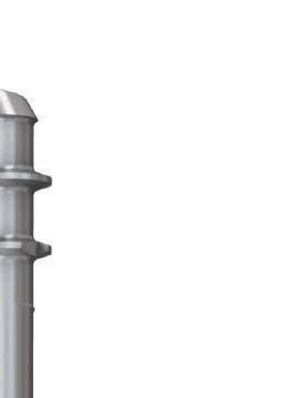
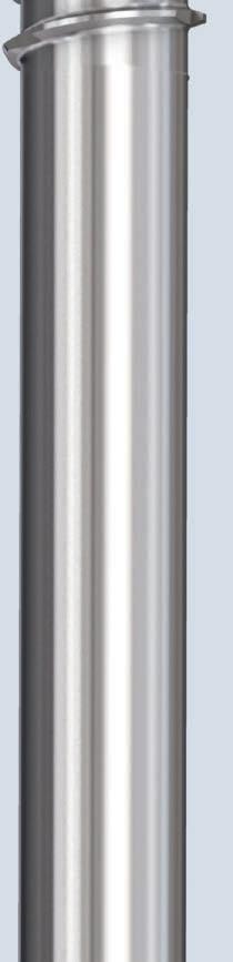
3 6.5 mm Midfoot Fusion Bolt The Midfoot Fusion Bolt is a solid intramedullary implant that can be used to fuse the medial metatarsocuneiform, naviculocuneiform, and talonavicular joints. Other uses of the Midfoot Fusion Bolt are fusion of the lateral column, calcaneocuboid, and 4th metatarsocuboid joint. The Midfoot Fusion Bolt is designed to achieve permanent fusion of these joints in patients suffering from gross instability such as Charcot neuroarthropathy with or without collapse of the midfoot. The Midfoot Fusion Bolt aids in the fusion of the joints of the midfoot. Fusion of the midfoot can provide stabilization and alignment, enhancing the possibility of a functional foot and increasing the likelihood of limb salvage. 1, 2 The 6.5 mm Midfoot Fusion Bolt is: x A solid bolt, highly resistant to bending and shear loads x Headless, for complete countersinking x Able to achieve compression x Available in 50 mm 160 mm lengths x Available in stainless steel and titanium Features Blunt tip minimizes soft tissue damage if over-inserted Head thread has same pitch as lead thread (2.7 mm) Leading threads and shaft have the same diameter easy insertion with reduced risk of threads cutting out of the bone Solid 6.5 mm diameter for added strength in bending and shear loads Cutting thread allows easy insertion and countersinking into cortical bone 1. Johnson JE. Operative treatment of neuropathic arthropathy of the foot and ankle. J Bone Joint Surg Am. 1998;80-A: Simon SR, Tejwani SG, Wilson DL, Santner TJ, Denniston NL. Arthrodesis as an early alternative to nonoperative management of charcot arthropathy of the diabetic foot. J Bone Joint Surg Am. 2000;82-A(7): DePuy Synthes Trauma 6.5 mm Midfoot Fusion Bolt Surgical Technique


4 6.5 mm Midfoot Fusion Bolt Functional principle of threads in Midfoot Fusion Bolt Step 1. Midfoot Fusion Bolt insertion Insertion of the Midfoot Fusion Bolt with the compression T-handle. Step 2. Closure of gap and compression As the compression T-handle contacts the bone, it acts like a screwhead and allows closure of the gap by compression. Step 3. Countersinking Once the desired amount of compression is achieved, the bolt head is countersunk by holding the T-handle and turning the bolt into the bone with the screwdriver. 6.5 mm Midfoot Fusion Bolt Surgical Technique DePuy Synthes Trauma 3
5 AO Principles In 1958, the AO formulated four basic principles, which have become the guidelines for internal fixation 3 : Anatomic reduction Fracture reduction and fixation to restore anatomical relationships. Stable fixation Stability by fixation or splintage, as the personality of the fracture and the injury requires. Preservation of blood supply Preservation of the blood supply to soft tissue and bone by careful handling. Use of surgical technique that minimizes disruption of soft tissue and preserves vascular blood flow for bone healing. Early, active mobilization Early and safe mobilization of the part and patient. The implants, combined with AO technique, provide stable fracture fixation with minimal trauma to vascular supply. 3. müller ME, Allgöwer M, Schneider R, Willenegger R. Manual of Internal Fixation, 3rd Edition. Berlin: Springer DePuy Synthes Trauma 6.5 mm Midfoot Fusion Bolt Surgical Technique

6 Indications The Depuy Synthes 6.5 mm Midfoot Fusion Bolt is indicated for fracture fixation, osteotomies, nonunions, and fusions of large bones in the foot and ankle. Warning: The Midfoot Fusion Bolt is not to be used as a standalone implant and needs to be used with supplemental fixation, such as additional screws and plates across the arthrodesed joints. 6.5 mm Midfoot Fusion Bolt Surgical Technique DePuy Synthes Trauma 5
7 Preoperative Planning Evaluation of x-rays For good preoperative planning it is important to have the following x-rays: x Weight-bearing in three projections: Lateral, AP, 45º oblique AP x AP of ankle x Comparative x-rays of both sides Preoperative examination and evaluation Estimate the balance of the foot and the function of the vital tendons, especially the length of the Achilles tendon and gastrocnemius. A gastrocnemius slide or percutaneous tendo-achilles lengthening is needed as equinus contracture causes abnormally high stresses across the midfoot. 6 DePuy Synthes Trauma 6.5 mm Midfoot Fusion Bolt Surgical Technique

8 Preparation 1 Position patient Place the patient in the supine position, with a roll under the affected hip to position the foot in neutral (toes straight up in a resting position). 2 Perform gastrocnemius slide or percutaneous tendo-achilles lengthening A gastrocnemius slide or percutaneous tendo-achilles lengthening is usually needed to relieve stresses across the midfoot. 6.5 mm Midfoot Fusion Bolt Surgical Technique DePuy Synthes Trauma 7

9 Preparation 3 Approach Two or three incisions are usually needed to expose and prepare the joints to be fused. Make a medial utility incision to expose and denude the talonavicular, navicular cuneiform, and tarsometatarsal joints. Take care to avoid the tibialis anterior tendon. Make a dorsal straight incision over the first metatarsal phalangeal joint (MPJ) to expose the joint. This allows access for the drill bit and midfoot fusion bolt through the first metatarsal articular surface. Note: At this stage of the procedure a subtalar fusion may be performed, if necessary. 8 DePuy Synthes Trauma 6.5 mm Midfoot Fusion Bolt Surgical Technique
10 Preparation 4 Prepare joints Instrument * 2.0 mm Kirschner Wire, trocar point, 150 mm Expose and prepare all the joints for fusion. Correct deformities with resections, where necessary. These corrections should be performed to the estimated final shape of the foot. Place temporary K-wires to hold the joints in place, taking care not to place them in the path of the final implant. Note: If desired add graft before provisionally fixing the joints with K-wires. 5 Prepare metatarsal Access the first metatarsal head through the dorsal incision. *Also available 6.5 mm Midfoot Fusion Bolt Surgical Technique DePuy Synthes Trauma 9


11 Implantation 1 Insert guide wire Instruments mm Non-Threaded Guide Wire, trocar point, 300 mm mm/ 8.5 mm Protection Sleeve mm/ 2.8 mm Wire Sleeve Insert the 2.8 mm guide wire, under image intensifier control, through the upper center of the first metatarsal head close to the dorsal cortex and straight across the tarsometatarsal, the navicular cuneiform, and the talonavicular joints into the talus. Insert the guide wire to the depth required. Note: Measurement is to the tip of the guide wire. 11 DePuy Synthes Trauma 6.5 mm Midfoot Fusion Bolt Surgical Technique
12 Implantation Alternative: reverse technique Instruments mm Non-Threaded Guide Wire, trocar point, 300 mm mm/ 8.5 mm Protection Sleeve mm/2.8 mm Wire Sleeve Insert the 2.8 mm guide wire under image intensifier control, through the upper center of the first metatarsal head, close to the dorsal cortex and straight across the tarsometatarsal, the navicular cuneiform, and the talonavicular joints, into the talus. Continue inserting the guide wire through the posterior of the talus making sure it exits posterior, avoiding the subtalar joint. From the back of the foot, readjust the guide wire position in the metatarsal head to allow measurement of the desired length of the midfoot fusion bolt. 6.5 mm Midfoot Fusion Bolt Surgical Technique DePuy Synthes Trauma 11


13 Implantation 2 Measure for bolt length Instrument Cannulated Screw Measuring Device, for 6.5 mm and 7.3 mm Cannulated Screws Place the measuring device over the guide wire and to the bone. Selected bolt length should reflect joint spaces, depth of countersink, and desired position of the leading tip of the bolt. Alternative: reverse technique Instrument Cannulated Screw Measuring Device for 6.5 mm and 7.3 mm Cannulated Screws Place the measuring device over the guide wire and to the bone. Selected bolt length should reflect joint spaces, depth of countersink, and desired position of the leading tip of the bolt. 11 DePuy Synthes Trauma 6.5 mm Midfoot Fusion Bolt Surgical Technique

14 Implantation 3 Drill Instruments mm Three-Fluted Cannulated Drill Bit, quick coupling, 300 mm, 200 mm calibration mm Cannulated Drill Bit, quick coupling, 330 mm When the reduction is complete, insert the 5.0 mm drill bit over the guide wire. Under image intensification, drill to the final desired position of the bolt. Note: The length of the bolt can also be checked with the calibrations on the 5.0 mm drill bit. Verify under image intensification that the drill bit follows the correct path and does not penetrate the end of the talus. It is recommended to over-drill the diameter of the bone with the 6.5 mm cannulated drill bit, especially in hard bone. Precaution: If overdrilling, do not drill the entire length of the bolt, as this will prevent purchase of the leading bolt threads. 6.5 mm drill bit 5.0 mm drill bit 6.5 mm Midfoot Fusion Bolt Surgical Technique DePuy Synthes Trauma 11
15 Implantation 3 Drill Alternative: reverse technique Instruments mm Three-Fluted Cannulated Drill Bit, quick coupling, 300 mm, 200 mm calibration mm Cannulated Drill Bit, quick coupling, 330 mm When the reduction is complete, insert the 5.0 mm drill bit over the guide wire. Under image intensification, drill to the final desired position of the bolt. Note: The length of the bolt can also be checked with the calibrations on the 5.0 mm drill bit. Verify under image intensification that the drill bit follows the correct path. It is recommended to over-drill the diameter of the bone with the 6.5 mm cannulated drill bit, especially in hard bone. 6.5 mm drill bit 5.0 mm drill bit Precaution: If overdrilling, do not drill the entire length of the bolt, as this will prevent purchase of the leading bolt threads. 11 DePuy Synthes Trauma 6.5 mm Midfoot Fusion Bolt Surgical Technique
16 Implantation 4 Remove guide wire Remove the guide wire to allow insertion of the solid midfoot fusion bolt. If stability is not maintained, add supplemental K-wires, ensuring that the wires are not in the path of the bolt. 5 Select midfoot fusion bolt Select the midfoot fusion bolt. Bolt length should reflect joint spaces, depth of countersink, and desired position of the leading tip of the bolt (Step 6). Important: It is important that the midfoot fusion bolt is inserted well into the body of the talus. Note: If there is excessive joint space, this should be considered when choosing the bolt. 6 Attach midfoot fusion bolt to T-handle Instrument T-Handle for Midfoot Fusion Bolt Connect the midfoot fusion bolt to the T-handle and finger-tighten. 6.5 mm Midfoot Fusion Bolt Surgical Technique DePuy Synthes Trauma 11
17 Implantation 7 Insert midfoot fusion bolt Insert the midfoot fusion bolt into the metatarsal head. Use image intensification to visualize and control bolt insertion. Place allograft or autograft in the prepared joints, if required. Turn the T-handle until it reaches the cartilage of the joint. 11 DePuy Synthes Trauma 6.5 mm Midfoot Fusion Bolt Surgical Technique
18 Implantation Alternative: reverse technique Insert the midfoot fusion bolt. Use image intensification to visualize and control bolt insertion. Place allograft or autograft in the prepared joints, if required. Turn the T-handle until it reaches the posterior of the talus. 6.5 mm Midfoot Fusion Bolt Surgical Technique DePuy Synthes Trauma 11
19 Implantation 8 Compress joints Under image intensification turn the T-handle until the desired compression is achieved. Alternative: reverse technique Under image intensification turn the T-handle until the desired compression is achieved. 11 DePuy Synthes Trauma 6.5 mm Midfoot Fusion Bolt Surgical Technique

20 Implantation 9 Countersink midfoot fusion bolt Instrument Screwdriver STARDRIVE TM, T25, with groove, 240 mm Place the STARDRIVE Screwdriver through the cannulation in the T-handle and engage the screwdriver in the head of the bolt. Hold the T-handle stationary and use the screwdriver to countersink the threaded head of the midfoot fusion bolt into the metatarsal. Note: The top of the thread is even with the bone surface when the groove in the screwdriver aligns with the top of the T-handle. Check the length of the midfoot fusion bolt, making sure that it is inserted well into the body of the talus. Precaution: If the bolt is short, there is a risk of cut-out along the plantar aspect of the distal talus when full weight-bearing starts. 6.5 mm Midfoot Fusion Bolt Surgical Technique DePuy Synthes Trauma 11
21 Implantation 9 Countersink midfoot fusion bolt Alternative: reverse technique Instrument Screwdriver STARDRIVE, T25, with groove, 240 mm Place the STARDRIVE Screwdriver through the cannulation in the T-handle and engage the screwdriver in the head of the bolt. Hold the T-handle stationary and use the screwdriver to countersink the threaded head of the midfoot fusion bolt into the posterior of the talus. 22 DePuy Synthes Trauma 6.5 mm Midfoot Fusion Bolt Surgical Technique


22 Supplemental Fixation The Midfoot Fusion Bolt is to be used with supplemental fixation, such as additional screws and plates across the arthrodesed joints. DePuy Synthes Companies of Johnson & Johnson offers a wide selection of plates and screws which cover a correspondingly extensive variety of indications. For this reason this technical guide does not cover specific indications or the selection of a plate type for specific clinical situations. For treatment of these subjects, please refer to AO Principles of Fracture Management courses offered by the AO ( and the corresponding professional literature. 6.5 mm Midfoot Fusion Bolt Surgical Technique DePuy Synthes Trauma 22
23 Postoperative Treatment and Implant Removal (optional) Postoperative treatment Immobilization in a well-padded splint for the first two weeks. During this time a dependent position should be avoided. The dressing is removed at two weeks, the wound is evaluated and gentle range of motion of the ankle and first metatarsophalangeal joints is initiated. Full weight-bearing between 10 to 12 weeks based on radiographic evidence of healing. Implant removal (optional) Instruments T-Handle for Midfoot Fusion Bolt STARDRIVE Screwdriver, T25, with groove, 240 mm Clear tissue ingrowth from the STARDRIVE Recess at the end of the bolt. Screw the bolt out until the head is no longer engaged in the bone. Attach the T-handle, place the STARDRIVE Screwdriver through the cannulation in the T-handle, and engage the screwdriver in the head of the bolt. Holding the T-handle, turn the screwdriver counterclockwise to partially engage the bolt in the T-handle. Remove the screwdriver. While pulling gently, turn the T-handle counterclockwise. 22 DePuy Synthes Trauma 6.5 mm Midfoot Fusion Bolt Surgical Technique
24 Implants 6.5 mm Midfoot Fusion Bolts Stainless Steel Titanium length (mm) Available nonsterile and sterile packed. Add S to catalog number for sterile product. For detailed cleaning and sterilization instructions, please refer to: In Canada, the cleaning and sterilization instructions will be provided with the Loaner shipments. MR INFORMATION This device has not been evaluated for safety and compatibility in the MR environment. This device has not been tested for heating or migration in the MR environment. 6.5 mm Midfoot Fusion Bolt Surgical Technique DePuy Synthes Trauma 22


25 Instruments mm Non-Threaded Guide Wire, trocar point, 300 mm T-Handle for Midfoot Fusion Bolt mm Three-Fluted Cannulated Drill Bit, quick coupling, 300 mm, 200 mm calibration mm/ 8.5 mm Protection Sleeve mm/ 2.8 mm Wire Sleeve STARDRIVE Screwdriver, T25, 240 mm, with groove 22 DePuy Synthes Trauma 6.5 mm Midfoot Fusion Bolt Surgical Technique

26 Instruments Cannulated Screw Measuring Device, for 6.5 mm and 7.3 mm Cannulated Screws Large Quick Coupling mm Cannulated Drill Bit, quick coupling, 330 mm 6.5 mm Midfoot Fusion Bolt Surgical Technique DePuy Synthes Trauma 22
 02.111.150 04.111.150 50 02.111.155 04.111.155 55 02.111.160 04.111.160 60 02.111.165 04.111.165 65 02.111.170 04.111.170 70 02.111.175 04.111.175 75 02.111.180 04.")

27 6.5 mm Midfoot Fusion Bolt Sets Stainless Steel ( ) and Titanium ( ) Graphic Case mm Midfoot Fusion Bolt Graphic Case Implants 6.5 mm Midfoot Fusion Bolts, 2 ea. Stainless Steel Titanium length (mm) DePuy Synthes Trauma 6.5 mm Midfoot Fusion Bolt Surgical Technique
28 Instruments mm Non-Threaded Guide Wire, trocar point, 300 mm, 8 ea T-Handle for Midfoot Fusion Bolt mm Three-Fluted Cannulated Drill Bit, quick coupling, 300 mm, 200 mm calibration mm/ 8.5 mm Protection Sleeve mm/ 2.8 mm Wire Sleeve STARDRIVE Screwdriver, T25, with groove, 240 mm Cannulated Screw Measuring Device, for 6.5 mm and 7.3 mm Cannulated Screws Large Quick Coupling mm Cannulated Drill Bit, quick coupling, 330 mm Also Available lid for 6.5 mm Midfoot Fusion Bolt Graphic Case Instrument Tray for 6.5 mm Midfoot Fusion Bolt Graphic Case mm Kirschner Wire, trocar point, 150 mm mm Cannulated Drill Bit, large quick coupling, 300 mm 6.5 mm Midfoot Fusion Bolt Surgical Technique DePuy Synthes Trauma 22
29 CAUTION: Federal Law Restricts These Devices To Sale By Or On The Order Of A Physician. Some devices listed in this technique guide may not have been licensed in accordance with Canadian law and may not be for sale in Canada. Please contact your sales consultant for items approved for sale in Canada. Manufactured by (United States): Synthes USA Products, LLC 1302 Wrights Lane East West Chester, PA Telephone: (610) To order: (800) Fax: (610) Legal manufacturer (Canada): Synthes (Canada) Ltd Meadowpine Boulevard Mississauga, Ontario L5N 6P9 Telephone: (905) To order: (800) Fax: (905) DePuy Synthes Trauma, a division of DOI All rights reserved. DSUS/TRM/0814/ /14
Technique Guide. 6.5 mm Midfoot Fusion Bolt. For intramedullary fixation of the medial column of the foot.
 Technique Guide 6.5 mm Midfoot Fusion Bolt. For intramedullary fixation of the medial column of the foot. Table of Contents Introduction 6.5 mm Midfoot Fusion Bolt 2 AO Principles 4 Indications 5 Surgical
Midfoot Fusion Bolt 6.5 mm. Intramedullary fixation of the medial column of the foot.
 Midfoot Fusion Bolt 6.5 mm. Intramedullary fixation of the medial column of the foot. Surgical Technique This publication is not intended for distribution in the USA. Instruments and implants approved
3.5 mm LCP Extra-articular Distal Humerus Plate
 Part of the DePuy Synthes Locking Compression Plate (LCP ) System 3.5 mm LCP Extra-articular Distal Humerus Plate Surgical Technique Table of Contents Introduction 3.5 mm LCP Extra-articular Distal Humerus
Technique Guide. 3.5 mm LCP Low Bend Medial Distal Tibia Plates. Part of the Synthes locking compression plate (LCP) system.
 system.") Technique Guide 3.5 mm LCP Low Bend Medial Distal Tibia Plates. Part of the Synthes locking compression plate (LCP) system. Table of Contents Introduction 3.5 mm LCP Low Bend Medial Distal Tibia Plates
Technique Guide 3.5 mm LCP Low Bend Medial Distal Tibia Plates. Part of the Synthes locking compression plate (LCP) system. Table of Contents Introduction 3.5 mm LCP Low Bend Medial Distal Tibia Plates
Low Bend Distal Tibia Plates
 Part of the DePuy Synthes Locking Compression Plate (LCP ) System 3.5 mm LCP Low Bend Medial Distal Tibia Plates Surgical Technique Table of Contents Introduction 3.5 mm LCP Low Bend Medial Distal Tibia
3.5 mm LCP Olecranon Plates
 Part of the DePuy Synthes Locking Compression Plate (LCP ) System 3.5 mm LCP Olecranon Plates Surgical Technique Table of Contents Introduction 3.5 mm LCP Olecranon Plates 2 AO Principles 3 Indications
Technique Guide. 3.5 mm LCP Olecranon Plates. Part of the Synthes locking compression plate (LCP) system.
 system.") Technique Guide 3.5 mm LCP Olecranon Plates. Part of the Synthes locking compression plate (LCP) system. Table of Contents Introduction 3.5 mm LCP Olecranon Plates 2 AO Principles 3 Indications 3 Clinical
Technique Guide 3.5 mm LCP Olecranon Plates. Part of the Synthes locking compression plate (LCP) system. Table of Contents Introduction 3.5 mm LCP Olecranon Plates 2 AO Principles 3 Indications 3 Clinical
Technique Guide. 3.5 mm LCP Low Bend Medial Distal Tibia Plate Aiming Instruments. Part of the 3.5 mm LCP Percutaneous Instrument System.
 Technique Guide 3.5 mm LCP Low Bend Medial Distal Tibia Plate Aiming Instruments. Part of the 3.5 mm LCP Percutaneous Instrument System. Table of Contents Introduction 3.5 mm LCP Low Bend Medial Distal
3.5 mm Locking Attachment Plate
 For Treatment of Periprosthetic Fractures 3.5 mm Locking Attachment Plate Surgical Technique Table of Contents Introduction 3.5 mm Locking Attachment Plate 2 Indications 4 Surgical Technique Preparation
2.7 mm/3.5 mm LCP Distal Fibula Plate
 Part of the DePuy Synthes Locking Compression Plate (LCP ) System 2.7 mm/3.5 mm LCP Distal Fibula Plate Surgical Technique Table of Contents Introduction 2.7 mm/3.5 mm LCP Distal Fibula Plates 2 AO Principles
2.4 mm Variable Angle LCP Intercarpal Fusion System. Variable angle locking technology for mediocarpal partial arthrodesis.
 2.4 mm Variable Angle LCP Intercarpal Fusion System. Variable angle locking technology for mediocarpal partial arthrodesis. Technique Guide Instruments and implants approved by the AO Foundation Table
Part of the DePuy Synthes Locking Compression Plate (LCP ) System. 3.5 mm LCP Medial Proximal Tibia Plates
 System. 3.5 mm LCP Medial Proximal Tibia Plates") Part of the DePuy Synthes Locking Compression Plate (LCP ) System 3.5 mm LCP Medial Proximal Tibia Plates Surgical Technique Table of Contents Introduction 3.5 mm LCP Medial Proximal Tibia Plates 2 AO
Part of the DePuy Synthes Locking Compression Plate (LCP ) System 3.5 mm LCP Medial Proximal Tibia Plates Surgical Technique Table of Contents Introduction 3.5 mm LCP Medial Proximal Tibia Plates 2 AO
Technique Guide. 3.5 mm LCP Periarticular Proximal Humerus Plate. Part of the Synthes locking compression plate (LCP) system.
 system.") Technique Guide 3.5 mm LCP Periarticular Proximal Humerus Plate. Part of the Synthes locking compression plate (LCP) system. Table of Contents Introduction 3.5 mm LCP Proximal Humerus Plate 2 AO Principles
Technique Guide 3.5 mm LCP Periarticular Proximal Humerus Plate. Part of the Synthes locking compression plate (LCP) system. Table of Contents Introduction 3.5 mm LCP Proximal Humerus Plate 2 AO Principles
Technique Guide. 2.7 mm/3.5 mm LCP Distal Fibula Plates. Part of the Synthes locking compression plate (LCP) system.
 system.") Technique Guide 2.7 mm/3.5 mm LCP Distal Fibula Plates. Part of the Synthes locking compression plate (LCP) system. Table of Contents Introduction 2.7 mm/3.5 mm LCP Distal Fibula Plates 2 AO Principles
Technique Guide 2.7 mm/3.5 mm LCP Distal Fibula Plates. Part of the Synthes locking compression plate (LCP) system. Table of Contents Introduction 2.7 mm/3.5 mm LCP Distal Fibula Plates 2 AO Principles
3.5 mm Clavicle Hook Plates
 A Single Solution for Lateral Clavicle Fractures and Acromioclavicular Joint Dislocations 3.5 mm Clavicle Hook Plates Surgical Technique Discontinued December 2017 DSUS/TRM/1016/1126(1) Table of Contents
3.5 mm LCP Hook Plate
 Part of the DePuy Synthes Locking Compression Plate (LCP ) System 3.5 mm LCP Hook Plate Surgical Technique Table of Contents Introduction 3.5 mm LCP Hook Plate 2 AO Principles 4 Indications 5 Clinical
Long Volar Plates for Diaphyseal-Metaphyseal Radius Fractures LCP. Dia-Meta Volar Distal Radius Plates. Surgical Technique
 Long Volar Plates for Diaphyseal-Metaphyseal Radius Fractures LCP Dia-Meta Volar Distal Radius Plates Surgical Technique Table of Contents Introduction LCP Dia-Meta Volar Distal Radius Plates 2 AO Principles
Surgical Technique. Customer Service:
 Patent and Patent Pending CAUTION: Federal Law (USA) restricts this device to sale by or on the order of a physician. INDICATIONS FOR USE The Axis Charcot Fixation System in diameters of 5.5, 6.5 and 7.5mm
Technique Guide. 2.4 mm Variable Angle LCP Distal Radius System. For fragment-specific fracture fixation with variable angle locking technology.
 Technique Guide 2.4 mm Variable Angle LCP Distal Radius System. For fragment-specific fracture fixation with variable angle locking technology. Table of Contents Introduction 2.4 mm Variable Angle LCP
The Locking Calcaneal Plate Instrument and Implant Sets
 Part of the DePuy Synthes Locking Compression Plate (LCP ) System The Locking Calcaneal Plate Instrument and Implant Sets Surgical Technique Table of Contents Introduction Locking Calcaneal Plate 2 AO
3.5 mm LCP Low Bend Medial Distal Tibia Plate Aiming Instruments
 Part of the 3.5 mm LCP 3.5 mm LCP Low Bend Medial Distal Tibia Plate Aiming Instruments Surgical Technique TABLE OF CONTENTS INTRODUCTION 3.5 mm LCP Low Bend Medial Distal Tibia Plate 2 Aiming Instruments
3.5 mm LCP Tibial Plateau Sets. Configuration options.
 3.5 mm LCP Tibial Plateau Sets. Configuration options. Multiple trays Multiple levels Multiple options 3.5 mm LCP Tibial Plateau Sets The tibial plateau trays allow the hospital to build a custom - ized
low ProfIle neuro PlaTIng system
 low ProfIle neuro PlaTIng system surgical TeChnIque Table of Contents Introduction Low Profile Neuro Cranial Plating System 2 Surgical Technique Technique 5 Product Information Low Profile Neuro Plates
Surgical Technique 4.5/8.5MM BEAMING SYSTEM. Customer Service:
 Patent and Patent Pending CAUTION: Federal Law (USA) restricts this device to sale by or on the order of a physician. INDICATIONS FOR USE The 4.5/8.5 screw system is intended for fixation arthrodesis of
3.5 mm VarIable angle lcp medial column fusion PlatIng SYStem. Part of the 2.7 mm and 3.5 mm VA LCP Midfoot/Hindfoot System
 3.5 mm VarIable angle lcp medial column fusion PlatIng SYStem Part of the 2.7 mm and 3.5 mm VA LCP Midfoot/Hindfoot System SurgIcal technique table of contents Introduction AO Principles and Indications
LCP Low Bend Medial Distal Tibia Plates 3.5 mm. Anatomic plates with low profile head for intra- and extraarticular fractures.
 LCP Low Bend Medial Distal Tibia Plates 3.5 mm. Anatomic plates with low profile head for intra- and extraarticular fractures. Surgical Technique This publication is not intended for distribution in the
3.5 mm LCP Clavicle Hook Plates
 Part of the Synthes Locking Compression Plate (LCP ) System 3.5 mm LCP Clavicle Hook Plates Surgical Technique Table of Contents Introduction 3.5 mm LCP Clavicle Hook Plates 2 AO Principles 4 Indications
4.5 mm LCP Medial Proximal Tibia Plates
 Part of the DePuy Synthes LCP Periarticular Plating System 4.5 mm LCP Medial Proximal Tibia Plates Surgical Technique Table of Contents Introduction 4.5 mm LCP Medial Proximal Tibia Plates 2 AO Principles
Distal Radius Plate Instrument and Implant Set. Discontinued December 2017 DSUS/TRM/0916/1063(1)
") Distal Radius Plate Instrument and Implant Set Surgical Technique Discontinued December 2017 DSUS/TRM/0916/1063(1) The Distal Radius Plates Indications For fixation of fractures and osteotomies, including
Distal Radius Plate Instrument and Implant Set Surgical Technique Discontinued December 2017 DSUS/TRM/0916/1063(1) The Distal Radius Plates Indications For fixation of fractures and osteotomies, including
2.4 mm LCP Radial Head Plates. Part of the Synthes LCP Distal Radius Plate System.
 2.4 mm LCP Radial Head Plates. Part of the Synthes LCP Distal Radius Plate System. Technique Guide Instruments and Implants approved by the AO Foundation Table of Contents Introduction 2.4 mm LCP Radial
3.5 mm LCP Anterolateral Distal Tibia Plates
 Part of the DePuy Synthes Locking Compression Plate (LCP ) System 3.5 mm LCP Anterolateral Distal Tibia Plates Surgical Technique Table of Contents Introduction 3.5 mm LCP Anterolateral Distal Tibia Plates
Thoracolumbar Spine Locking Plate (TSLP) System. A low-profile plating system for anterior stabilization of the thoracic and lumbar spine.
 System. A low-profile plating system for anterior stabilization of the thoracic and lumbar spine.") Thoracolumbar Spine Locking Plate (TSLP) System. A low-profile plating system for anterior stabilization of the thoracic and lumbar spine. Technique Guide Instruments and implants approved by the AO Foundation
Thoracolumbar Spine Locking Plate (TSLP) System. A low-profile plating system for anterior stabilization of the thoracic and lumbar spine. Technique Guide Instruments and implants approved by the AO Foundation
Compact Distal Radius System. Consolidated solution for Distal Radius Plating Systems
 Compact Distal Radius System. Consolidated solution for Distal Radius Plating Systems Designed to allow customized system configurations Variable Angle (VA) and Locking Compression Plate (LCP ) options
3.5 mm LCP Distal Humerus Plates
 Part of the DePuy Synthes Locking Compression Plate (LCP ) System 3.5 mm LCP Distal Humerus Plates Surgical Technique Table of Contents Introduction 3.5 mm LCP Distal Humerus Plates 2 AO Principles 4 Indications
LCP Anterior Ankle Arthrodesis Plates. Part of the Synthes Locking Compression Plate (LCP) System.
 System.") LCP Anterior Ankle Arthrodesis Plates. Part of the Synthes Locking Compression Plate (LCP) System. Technique Guide Instruments and implants approved by the AO Foundation Table of Contents Introduction
LCP Anterior Ankle Arthrodesis Plates. Part of the Synthes Locking Compression Plate (LCP) System. Technique Guide Instruments and implants approved by the AO Foundation Table of Contents Introduction
LCP Medial Proximal Tibial Plate 3.5. Part of the Synthes small fragment Locking Compression Plate (LCP) system.
 system.") LCP Medial Proximal Tibial Plate 3.5. Part of the Synthes small fragment Locking Compression Plate (LCP) system. Technique Guide This publication is not intended for distribution in the USA. Instruments
LCP Medial Proximal Tibial Plate 3.5. Part of the Synthes small fragment Locking Compression Plate (LCP) system. Technique Guide This publication is not intended for distribution in the USA. Instruments
Technique Guide. TomoFix Osteotomy System. A comprehensive plating system for stable fixation of osteotomies around the knee.
 Technique Guide TomoFix Osteotomy System. A comprehensive plating system for stable fixation of osteotomies around the knee. Table of Contents Introduction TomoFix Osteotomy System 2 AO Principles 4 Indications
Lag Screw Device Intended for symphyseal fracture fixation of the mandible
 Lag Screw Device Intended for symphyseal fracture fixation of the mandible SUrgicaL TecHNiqUe Lag Screw Device Intended for symphyseal fracture fixation of the mandible Simplifies the lag screw fixation
3.5 MM VA-LCP PROXIMAL TIBIA PLATE SYSTEM
 3.5 MM VA-LCP PROXIMAL TIBIA PLATE SYSTEM Part of the DePuy Synthes Variable Angle Periarticular Plating System SURGICAL TECHNIQUE TABLE OF CONTENTS INTRODUCTION 3.5 mm VA-LCP Proximal Tibial Plate 2 AO
2.4 mm Variable Angle LCP Volar Extra-Articular Distal Radius System. For fragment-specific fracture fixation with variable angle locking technology.
 Technique Guide 2.4 mm Variable Angle LCP Volar Extra-Articular Distal Radius System. For fragment-specific fracture fixation with variable angle locking technology. Table of Contents Introduction 2.4
LCP Medial Proximal Tibial Plate 4.5/5.0. Part of the Synthes LCP periarticular plating system.
 LCP Medial Proximal Tibial Plate 4.5/5.0. Part of the Synthes LCP periarticular plating system. Technique Guide This publication is not intended for distribution in the USA. Instruments and implants approved
LCP Anterolateral Distal Tibia Plate 3.5. The low profile anatomic fixation system with optimal plate placement and angular stability.
 LCP Anterolateral Distal Tibia Plate 3.5. The low profile anatomic fixation system with optimal plate placement and angular stability. Technique Guide LCP Small Fragment System Table of Contents Introduction
2.4 mm Variable Angle Locking Intercarpal Fusion System
 For Partial Wrist Arthrodesis With Variable Angle Locking Technology 2.4 mm Variable Angle Locking Intercarpal Fusion System Surgical Technique Table of Contents Introduction 2.4 mm Variable Angle Locking
LCP Anterolateral Distal Tibia Plate 3.5. The low profile anatomic fixation system with optimal plate placement and angular stability.
 LCP Anterolateral Distal Tibia Plate 3.5. The low profile anatomic fixation system with optimal plate placement and angular stability. Technique Guide LCP Small Fragment System Table of Contents Introduction
LCP Medial Distal Tibia Plate, without Tab. The Low Profile Anatomic Fixation System with Angular Stability and Optimal Screw Orientation.
 LCP Medial Distal Tibia Plate, without Tab. The Low Profile Anatomic Fixation System with Angular Stability and Optimal Screw Orientation. Technique Guide LCP Small Fragment System Table of Contents Introduction
Technique Guide. Cranial Clamps with Application Instrument. Quick and stable fixation of cranial bone flaps following a craniotomy.
 Technique Guide Cranial Clamps with Application Instrument. Quick and stable fixation of cranial bone flaps following a craniotomy. Table of Contents Introduction Cranial Clamps with Application Instrument
Cannulated Pediatric Osteotomy System (CAPOS)
") A Single System of Osteotomy Blade Plates and Cannulated Instrumentation Cannulated Pediatric Osteotomy System (CAPOS) Surgical Technique Table of Contents Introduction Cannulated Pediatric Osteotomy System
A Single System of Osteotomy Blade Plates and Cannulated Instrumentation Cannulated Pediatric Osteotomy System (CAPOS) Surgical Technique Table of Contents Introduction Cannulated Pediatric Osteotomy System
2.7 mm/3.5 mm LCP Distal Fibula Plate System. Part of the Synthes locking compression plate (LCP) system.
 system.") 2.7 mm/3.5 mm LCP Distal Fibula Plate System. Part of the locking compression plate (LCP) system. Anatomically contoured Multiple screw options for fixedangle support Coaxial holes minimize screw head
2.7 mm/3.5 mm LCP Distal Fibula Plate System. Part of the locking compression plate (LCP) system. Anatomically contoured Multiple screw options for fixedangle support Coaxial holes minimize screw head
designed to advance the treatment of hip fractures.
 designed to advance the treatment of hip fractures. introducing the tfn-advanced proximal femoral nailing system (tfna). the tfna system is a new system designed to solve a wide range of unmet needs for
LCP Distal Femur Plates. Shape based on Distal Femur LISS Plate design.
 LCP Distal Femur Plates. Shape based on Distal Femur LISS Plate design. Preshaped plate Round threaded holes in plate head Combi holes in plate shaft LCP Distal Femur Plates Plates The LCP Distal Femur
Mandible External Fixator II. Provides treatment for fractures of the maxillofacial area.
 Mandible External Fixator II. Provides treatment for fractures of the maxillofacial area. Technique Guide This publication is not intended for distribution in the USA. Instruments and implants approved
Titanium Distal Femoral Nail System
 For Retrograde Insertion Titanium Distal Femoral Nail System Surgical Technique Table of Contents Introduction Titanium Distal Femoral Nail System 2 AO Principles 4 Indications 5 Clinical Cases 6 Surgical
3.5 mm LCP Distal Tibia T-Plates
 Part of the DePuy Synthes Locking Compression Plate (LCP ) System 3.5 mm LCP Distal Tibia T-Plates Surgical Technique Table of Contents Introduction 3.5 mm LCP Distal Tibia T-Plates 2 AO Principles 4 Indications
4.5 mm LCP Condylar Plate Aiming Instruments
 Part of the LCP Periarticular Aiming Instrument System (Large) 4.5 mm LCP Condylar Plate Aiming Instruments Surgical Technique Table of Contents Introduction 4.5 mm LCP Condylar Plate Aiming Instruments
Olecranon Osteotomy Nail. For simple fractures and osteotomies of the olecranon.
 Olecranon Osteotomy Nail. For simple fractures and osteotomies of the olecranon. Technique Guide Discontinued June 2016; AVAILABLE FOR IMPLANT REMOVAL PURPOSES ONLY DSEM/TRM/0517/0843 Table of Contents
2.4 mm Variable Angle LCP Volar Extra-Articular Distal Radius System. For fragment-specific fracture fixation with variable angle locking technology.
 2.4 mm Variable Angle LCP Volar Extra-Articular Distal Radius System. For fragment-specific fracture fixation with variable angle locking technology. Surgical Technique This publication is not intended
Low Profile Neuro Plating System. Surgical Technique
 Low Profile Neuro Plating System Surgical Technique TABLE OF CONTENTS INTRODUCTION Low Profile Neuro Plating System 2 SURGICAL TECHNIQUE Technique 5 PRODUCT INFORMATION Low Profile Neuro Plates 10 Low
Technique Guide. LCP Distal Fibula Plates. Part of the Synthes locking compression plate (LCP) system.
 system.") Technique Guide LCP Distal Fibula Plates. Part of the Synthes locking compression plate (LCP) system. Table of Contents Introduction LCP Distal Fibula Plates 2 AO Principles 4 Indications 5 Surgical Technique
Technique Guide LCP Distal Fibula Plates. Part of the Synthes locking compression plate (LCP) system. Table of Contents Introduction LCP Distal Fibula Plates 2 AO Principles 4 Indications 5 Surgical Technique
VA LCP MEDIAL COLUMN FUSION PLATES 3.5
 VA LCP MEDIAL COLUMN FUSION PLATES 3.5 Instruments and Implants approved by the AO Foundation. This publication is not intended for distribution in the USA. SURGICAL TECHNIQUE Image intensifier control
For Distal Femur Fractures. 95º Condylar Plate. Quick Reference Chart
 For Distal Femur Fractures 95º Condylar Plate Quick Reference Chart 95 Condylar Plate. Quick reference chart for distal femur fractures. Insert guide wires Fix condylar fragments with 6.5 mm cancellous
LCP DISTAL TIBIA PLATE
 LCP DISTAL TIBIA PLATE Instruments and implants approved by the AO Foundation. This publication is not intended for distribution in the USA. SURGICAL TECHNIQUE Image intensifier control This description
Pediatric LCP Plate System. For osteotomies and fracture fixation of the proximal and distal femur.
 Pediatric LCP Plate System. For osteotomies and fracture fixation of the proximal and distal femur. Angular stability Intraoperative correction and flexibility Universal design Indications The Pediatric
2.4 mm Variable Angle LCP Volar Rim Distal Radius Plates
 For Fragment-Specific Fracture Fixation With Variable Angle Locking Technology 2.4 mm Variable Angle LCP Volar Rim Distal Radius Plates Surgical Technique Table of Contents Introduction 2.4 mm Variable
Technique Guide. LCP Proximal Femoral Hook Plate 4.5/5.0. Part of the LCP Periarticular Plating System.
 Technique Guide LCP Proximal Femoral Hook Plate 4.5/5.0. Part of the LCP Periarticular Plating System. Table of Contents Introduction Features and Benefits 2 AO ASIF Principles 4 Indications 5 Surgical
Mini External Fixator
 Stabilize the Phalanges and Metacarpals Mini External Fixator Surgical Technique Table of Contents Introduction Mini External Fixator 2 Indications 4 Surgical Technique Technique Overview 5 Product Information
2.4 mm Variable Angle LCP Dorsal Distal Radius Plate
 For Fragment-Specific Fracture Fixation With Variable Angle (VA) Locking Technology 2.4 mm Variable Angle LCP Dorsal Distal Radius Plate Surgical Technique Table of Contents Introduction 2.4 mm VA LCP
VA-LCP Anterior Clavicle Plate. The anatomically precontoured fixation system with angular stability for clavicle shaft and lateral clavicle.
 Technique Guide VA-LCP Anterior Clavicle Plate. The anatomically precontoured fixation system with angular stability for clavicle shaft and lateral clavicle. Table of Contents Introduction VA-LCP Anterior
OBSOLETED. LCP Medial Distal Tibia Plate, without Tab. The Low Profile Anatomic Fixation System with Angular Stability and Optimal Screw Orientation.
 LCP Medial Distal Tibia Plate, without Tab. The Low Profile Anatomic Fixation System with Angular Stability and Optimal Screw Orientation. Surgical Technique LCP Small Fragment System This publication
LCP Periprosthetic System. Part of the Synthes locking compression plate (LCP) system.
 system.") LCP Periprosthetic System. Part of the Synthes locking compression plate (LCP) system. 4.5 mm LCP curved broad plates 5.0 mm periprosthetic locking screws Orthopaedic cable components LCP Periprosthetic
LCP Periprosthetic System. Part of the Synthes locking compression plate (LCP) system. 4.5 mm LCP curved broad plates 5.0 mm periprosthetic locking screws Orthopaedic cable components LCP Periprosthetic
CSLP Quick Lock Screws. Preassembled expansionhead screw and locking screw for use with Cervical Spine Locking Plates (CSLP).
.") CSLP Quick Lock Screws. Preassembled expansionhead screw and locking screw for use with Cervical Spine Locking Plates (CSLP). Technique Guide Instruments and implants approved by the AO Foundation Table
CSLP Quick Lock Screws. Preassembled expansionhead screw and locking screw for use with Cervical Spine Locking Plates (CSLP). Technique Guide Instruments and implants approved by the AO Foundation Table
LCP Proximal Radius Plates 2.4. Plates for radial head rim and for radial head neck address individual fracture patterns of the proximal radius.
 Technique Guide LCP Proximal Radius Plates 2.4. Plates for radial head rim and for radial head neck address individual fracture patterns of the proximal radius. Table of Contents Introduction LCP Proximal
Technique Guide. Compact 2.0 LOCK Mandible. The locking system for the mandible.
 Technique Guide Compact 2.0 LOCK Mandible. The locking system for the mandible. Table of Contents Introduction Compact 2.0 LOCK Mandible 2 AO Principles 4 Indications and Contraindications 5 Surgical
Integra. ADVANSYS Plating System SURGICAL TECHNIQUE
 Integra ADVANSYS Plating System SURGICAL TECHNIQUE Table of Contents Dorsal Lisfranc Plate Indications...2 Contraindications...2 Description...2 Surgical Technique...3 Surgical Site Preparation...3 Step
Technique Guide. PHILOS and PHILOS Long. The anatomic fixation system for the proximal humerus.
 Technique Guide PHILOS and PHILOS Long. The anatomic fixation system for the proximal humerus. Table of Contents Introduction PHILOS and PHILOS Long 2 AO Principles 4 Indications 5 Surgical Technique
Technique Guide. 4.5 mm LCP Proximal Tibia Plates. Part of the Synthes LCP Periarticular Plating System.
 Technique Guide 4.5 mm LCP Proximal Tibia Plates. Part of the Synthes LCP Periarticular Plating System. Table of Contents Introduction 4.5 mm LCP Proximal Tibia Plates 2 AO Principles 4 Indications 5 Surgical
3.5 mm LCP Superior and Superior Anterior Clavicle Plates. Part of the Synthes modular clavicle plate system.
 3.5 mm LCP Superior and Superior Anterior Clavicle Plates. Part of the Synthes modular clavicle plate system. Technique Guide Instruments and implants approved by the AO Foundation Table of Contents Introduction
LCP Distal Fibula Plates. Part of the Synthes locking compression plate (LCP) system.
 system.") LCP Distal Fibula Plates. Part of the Synthes locking compression plate (LCP) system. Surgical Technique This publication is not intended for distribution in the USA. Instruments and implants approved
LCP Distal Fibula Plates. Part of the Synthes locking compression plate (LCP) system. Surgical Technique This publication is not intended for distribution in the USA. Instruments and implants approved
3.5 mm LCP Superior Anterior Clavicle Plates
 Part of the DePuy Synthes Locking Compression Plate (LCP ) System 3.5 mm LCP Superior Anterior Clavicle Plates Surgical Technique Table of Contents Introduction 3.5 mm LCP Superior Anterior Clavicle Plates
DOUBLE/TRIPLE PELVIC OSTEOTOMY PLATES For Treating Coxofemoral Joint Instability and Subluxation in Immature Dogs
 DOUBLE/TRIPLE PELVIC OSTEOTOMY PLATES For Treating Coxofemoral Joint Instability and Subluxation in Immature Dogs Instruments and implants approved by the AO Foundation. This publication is not intended
Thoracolumbar Anterior Compression (TAC) System. Allows distraction, compression, and lateral fixation of the lower thoracic and lumbar spine.
 System. Allows distraction, compression, and lateral fixation of the lower thoracic and lumbar spine.") Thoracolumbar Anterior Compression (TAC) System. Allows distraction, compression, and lateral fixation of the lower thoracic and lumbar spine. Technique Guide Instruments and implants approved by the AO
Thoracolumbar Anterior Compression (TAC) System. Allows distraction, compression, and lateral fixation of the lower thoracic and lumbar spine. Technique Guide Instruments and implants approved by the AO
3.0/3.5/4.0/4.5/6.5/7.0/7.3. Cannulated Screws. Surgical Technique
 3.0/3.5/4.0/4.5/6.5/7.0/7.3 Cannulated Screws Surgical Technique Image intensifier control This description alone does not provide sufficient background for direct use of DePuy Synthes products. Instruction
CHARLOTTE. 3.0 and 4.3 Multi-Use Compression Screws SURGIC A L T ECHNIQUE
 CHARLOTTE 3.0 and 4.3 Multi-Use Compression Screws SURGIC A L T ECHNIQUE CHARLOTTE 3.0 and 4.3 Multi-Use Compression Screws SURGICAL TECHNIQUE Surgical Technique as described by: Robert Anderson, MD Bruce
Technique Guide. VA-Locking Intercarpal Fusion System. Variable angle locking technology for mediocarpal partial arthrodesis.
 Technique Guide VA-Locking Intercarpal Fusion System. Variable angle locking technology for mediocarpal partial arthrodesis. Table of Contents Introduction VA-Locking Intercarpal Fusion System 2 Indications
Trochanter Stabilization Plate for DHS Implants
 Extends DHS Plate Construct to Help Stabilize Greater Trochanter Trochanter Stabilization Plate for DHS Implants Surgical Technique Table of Contents Introduction Trochanter Stabilization Plate for DHS
The Wrist Fusion Set. Stainless Steel and Titanium TECHNIQUE GUIDE. Instruments and implants approved by the AO Foundation
 The Wrist Fusion Set Stainless Steel and Titanium TECHNIQUE GUIDE Instruments and implants approved by the AO Foundation Three Plate Options Stainless Steel or Titanium* Standard Bend Stainless Steel [242.510]
PEDUS-L. Locking Plantar Lapidus Plate
 PEDUS-L Locking Plantar Lapidus Plate Page 1 PEDUS-L - Locking Plantar Lapidus Plate Table of Contents Implants 3 System 4 Operation manual 5 Approach 5 Identification of the TMT 1 joint with a cannula
modular ClaVICle PlaTe system
 modular ClaVICle PlaTe system 3.7 mm/3.3 mm VA LCP Anterior Clavicle Plates and 3.3 mm Superior Anterior Clavicle Plates surgical TeChnIque Table of Contents Introduction Modular Clavicle Plate System
Orthopedic Bone Nail System - Distal Femoral Nail Surgical Technique Manual
 Orthopedic Bone Nail System - Distal Femoral Nail Surgical Technique Manual Note: The surgical procedures should be performed under the guidance of qualified skilled orthopedic surgeons, and this surgical
Technique Guide. Midface Distractor System. For the temporary stabilization and gradual lengthening of the cranial or midfacial bones.
 Technique Guide Midface Distractor System. For the temporary stabilization and gradual lengthening of the cranial or midfacial bones. Table of Contents Introduction Midface Distractor System 2 Indications
VA LOCKING CALCANEAL PLATES 2.7
 VA LOCKING CALCANEAL PLATES 2.7 Instruments and Implants approved by the AO Foundation. This publication is not intended for distribution in the USA. SURGICAL TECHNIQUE Image intensifier control Warning
4.5 mm VA-LCP. Part of the Variable Angle Periarticular Plating System
 4.5 mm VA-LCP Curved Condylar Plate Part of the Variable Angle Periarticular Plating System Surgical Technique Table of Contents Introduction 4.5 mm VA-LCP Curved Condylar Plates 2 4.5 mm VA-LCP Curved
Periarticular Aiming Arm Instruments for LCP Proximal Tibial Plate 4.5/5.0. Part of the LCP Periarticular Aiming Arm Instrument System (large).
.") Technique Guide Periarticular Aiming Arm Instruments for LCP Proximal Tibial Plate 4.5/5.0. Part of the LCP Periarticular Aiming Arm Instrument System (large). Image intensifier control Warning This description
Technique Guide Periarticular Aiming Arm Instruments for LCP Proximal Tibial Plate 4.5/5.0. Part of the LCP Periarticular Aiming Arm Instrument System (large). Image intensifier control Warning This description
Technique Guide. SureLock Distal Targeting Device. C-arm guided targeting for trochanteric fixation nail.
 Technique Guide SureLock Distal Targeting Device. C-arm guided targeting for trochanteric fixation nail. Table of Contents Introduction SureLock Distal Targeting Device 2 Surgical Technique Preoperative
The Flower Medial Column Fusion Plate
 The Flower Medial Column Fusion Plate PROCEDURE GUIDE www.flowerortho.com The Flower Foot & Ankle Application NC FUSION PLATE 2-HOLE COMPRESSION PLATE TMT FUSION PLATE LAPIDUS FUSION PLATE COMPRESSION
Pediatric LCP Hip Plate. For osteotomy and trauma applications in the proximal femur.
 Pediatric LCP Hip Plate. For osteotomy and trauma applications in the proximal femur. Angular stability Intraoperative correction and flexibility Universal design Pediatric LCP Hip Plate The Pediatric
Technique Guide. 3.5 mm LCP Proximal Tibia Plate. Part of the Synthes Small Fragment LCP System.
 Technique Guide 3.5 mm LCP Proximal Tibia Plate. Part of the Synthes Small Fragment LCP System. Table of Contents AO ASIF Principles of Internal Fixation 4 Indications/Contraindications 5 Surgical Technique
Technique Guide. LCP Posterior Medial Proximal Tibial Plate 3.5. Part of the Synthes small fragment LCP system.
 Technique Guide LCP Posterior Medial Proximal Tibial Plate 3.5. Part of the Synthes small fragment LCP system. Table of Contents Introduction LCP Posterior Medial Proximal Tibial Plate 3.5 2 AO Principles
LCP Wrist Fusion Set. Anatomic plates for total wrist fusion.
 LCP Wrist Fusion Set. Anatomic plates for total wrist fusion. Technique Guide This publication is not intended for distribution in the USA. Instruments and implants approved by the AO Foundation. Table
The CerviFix System. Including the StarLock Components. CerviFix Clamp and Screw. StarLock Clamp and Screw
 The CerviFix System Including the StarLock Components CerviFix Clamp and Screw StarLock Clamp and Screw The CerviFix System The CerviFix System is a comprehensive set of implants, including clamps, screws,
Occipital Cervical Fusion System. Implants and instruments designed to optimize fixation to the occiput.
 Occipital Cervical Fusion System. Implants and instruments designed to optimize fixation to the occiput. Technique Guide and implants approved by the AO Foundation Table of Contents Introduction Occipital