Product Rationale & Surgical Technique
|
|
|
- Pierce Scott
- 5 years ago
- Views:
Transcription


1 Product Rationale & Surgical Technique
2
3 Contents Surgeon Design Team 8 Introduction 9 1st Metatarsal Fusion Technique 12 Single Joint Fusion Plates Technique 22 Lateral Column Lengthening Plate Technique 32 Medial Column Fusion Technique 40 Dorsal Mid-Foot Fusion Technique 50 Locking Calcaneal Plate Technique 60 Navicular Fracture Plate Technique 70 Talar Neck Fracture Plate Technique Screw Options and Insertion Techniques 87 Small Frag Screw Options and Insertion Techniques 93 1
4 2
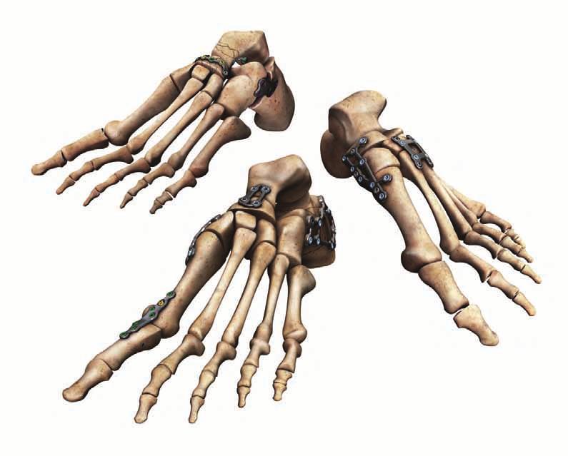
5 Low profile, anatomically contoured foot plates Low profile plate design helps minimize discomfort and soft tissue irritation. Engineered from TiMAX for strength, biocompatibility and enhanced imaging capabilities over stainless steel. A smooth implant surface and decreased soft tissue irritation. Contoured plates mimic the anatomy of the foot. Adapters available for fixed angle K-wire placement for provisional fixation. The A.L.P.S. Total Foot System is a comprehensive set of anatomically contoured implants to address a wide array of fusions and fractures in the forefoot, midfoot and hindfoot. The anatomic design of the plates are meant to closely match the natural anatomy. However, in-situ contouring is available for fine adjustment and patient specific customization. 3


6 4
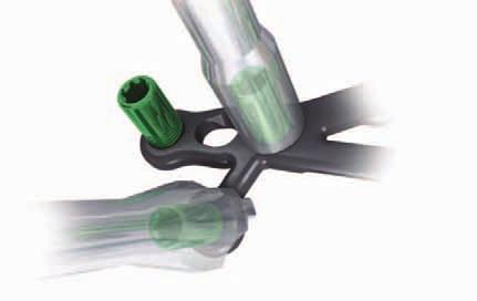
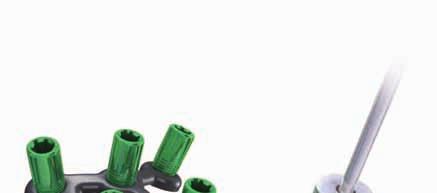
7 Fast, accurate surgeries F.A.S.T. Guide and F.A.S.T. Tabs technologies F.A.S.T. Guide Technology Pre-loaded and disposable F.A.S.T. Guides facilitate accurate drilling and reduce intraoperative assembly, saving time in the OR F.A.S.T. Tabs Technology F.A.S.T. Tabs Technology enables in-situ contouring for true plate-to-bone conformity. Provisional Fixation Easy K-wire placement through provisional fixation holes The A.L.P.S. Total Foot System comes pre-loaded with Fixed Angle Screw Targeting Guides - F.A.S.T. Guides - that direct the trajectory of the drill right through the plate. Additionally, F.A.S.T. Tabs technology allows for in-situ contouring for patient specific customization. 5

8 6
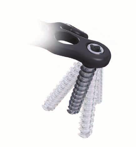
9 Locking, Non-Locking, and Multi-Directional Locking Screw options Choose locking, non-locking, or multi-directional locking screws according to need and without compromising plate profile. Tapered, threaded screws lock into position when tightened to establish a fixed angle construct for strong fixation or when bone quality is poor and optimal screw purchase is required. 2.5 mm Locking Multi-Directional Threaded Pegs (MDTP) allow up to a 20 degree cone, while the 3.5 mm Locking Multi-Directional Screws (MDS) allow a 25 or 30 degree cone depending on plate. Screws lock into plate by creating their own thread without the risk of cold welding. Low profile non-locking screws provide the same profile as locking screws. Unidirectional compression holes allow for axial compression. 7
10 Surgeon Design Team Mark S. Myerson, M.D. Orthopaedic Foot and Ankle Specialist Director, The Institute for Foot and Ankle Reconstruction at Mercy Medical Center Baltimore, MD Roy Sanders, M.D. Chief, Department of Orthopaedics, Tampa General Hospital Director, Orthopaedic Trauma Services, Florida Orthopaedic Institute Tampa, Florida 8
11 Introduction The A.L.P.S. Foot System offers a comprehensive set of plating options anatomically contoured to address - osteotomies, fusions and fractures in the forefoot, midfoot and hindfoot. The attention to anatomic detail is further enhanced by deliberate regions of flexibility to accommodate individual anatomic variation without compromising strength. The A.L.P.S. Foot System also offers a wide array of both locking and non-locking screw options and incorporates industry leading F.A.S.T. Guide technology. The result is a comprehensive yet flexible system that improves operating room efficiency and ease of use. Indications for Use: System is intended for use in stabilization and fixation of fractures, revision procedures, fusions, reconstructions (osteotomy) and non-unions of the bones of the hand, foot, wrist, ankle, finger, toe, humerus, olecranon, clavicle, scapula and pelvis, particularly in osteopenic bone. The system can be used in both adult and pediatric patients (adolescents [>12-21 years of age]), where the implant would not cross open epiphyseal plates in skeletally immature patients. 9
12 10

13 R E C O N 1ST METATARSAL FUSION These are images of models with bones shown with plates in place and not real patients. They are provided to show positioning and not intended to suggest immediate weight bearing.
14 R E C O N 1ST METATARSAL FUSION
15 11
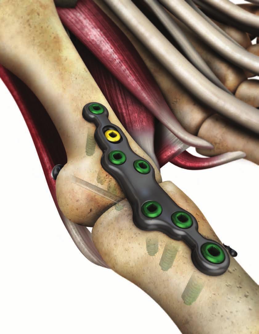
16 1st Metatarsal Fusion Technique: The A.L.P.S. 1st Metatarsophalangeal (MTP) Joint Fusion plates are made of a titanium alloy (Ti6Al4V) with a TiMAX treatment for increased fatigue strength compared to the standard alloy. The low-profile anatomic design (1.65 mm thickness) and highly contoured surface minimizes potential soft tissue irritation. The 1st MTP Plate is available in both right and left options and has a pre-contoured buttress support with 14 degrees of dorsiflexion and 5 degrees of valgus for excellent anatomic alignment. Offset fixation screws provide a convenient corridor for additional interfragmentary screw fixation and have convergent trajectories for improved plate stability. Proprietary F.A.S.T. Guide technology provides a number of unique features to promote operating room efficiency and facilitate implant selection. The plate offers numerous screw options including: 2.5 mm Cortical Locking, 2.5 mm Cortical Non-Locking, and 2.5 mm Multi-Directional Locking Screws all designed to maintain a low profile plate and screw construct. 12


 F.A.S.T.")
17 1st Metatarsal Fusion Plate TiMAX for strength, biocompatibility and enhanced imaging capabilities over Stainless Steel Threaded holes accept locking 2.5 mm, as well as 2.5 mm Non-Locking Screws Low profile construct with highly contoured surfaces Pre-contoured high strength center section with 14 degrees of dorsiflexion and 5 degrees of valgus 2.5 mm Multi-Directional Locking Screws allow for up to a 20 degree cone of angulation Right (Rose) F.A.S.T. Guide inserts for easy accurate drilling Distal The plate has an integrated fixation corridor designed to facilitate interfragmentary screw fixation Left (Lime) Proximal 13


18 Exposure and Plate Placement The following surgical technique applies to the fusion of the 1st Metatarsophalangeal (MTP) joint. Step 1: Exposure & Alignment Perform a longitudinal incision beginning just proximal to the interphalangeal joint and extend over the 1st MTP joint medial to the extensor hallucis longus. Expose the proximal phalanx and metatarsal head and denude all cartilage surfaces exposing the bleeding subchondral bone. If shortening of the metatarsal is a concern, place bone graft within the arthrodesis site. Use a K-wire to provisionally fix the joint at the desired angle. If an interfragmentary cross screw is used, position the guide wire prior to positioning the plate. Dorsal placement of the 1st Metatarsophalangeal Joint Fusion plate Step 2 Step 2: Plate Placement The plate should be positioned dorsally such that it permits the placement of the screws adjacent to the joint line. Partially insert a 2.5 mm Non-Locking Screw (Cat. No. SPXX000) through the oval hole of the plate to allow distal to proximal optimization of the plate position. (Step 2) Note: The oval hole is not a compressive hole to avoid altering the dorsiflexion angle. Note: A detailed technique for screw insertion can be found in the 2.5 mm screw section of this technique guide. 14


19 Optional Plate Contouring Remove only the two inner most F.A.S.T. Guides from the high strength region Figure 1 Note: The high strength sections of the A.L.P.S. Foot 1st MTP plates are pre-contoured. If bending of this section is required to match patient specific anatomy, use the following technique to further contour the plate. Caution: Each bend should be in one direction only; reverse or over bending may weaken or cause plate to break. Do not alter the flexion angle by more than 10 degrees in either direction. Use the slotted end of the Double F.A.S.T. Guide Bender (Cat No ) Figure 2 With the plate contoured, replace the F.A.S.T. Guides Figure 4 Note: To replace the F.A.S.T. Guides and prevent possible cross threading, it is helpful to initially turn the F.A.S.T. Guide counter clockwise ¼ turn before fully inserting the F.A.S.T. Guide. Reduce or increase dorsiflexion angle by bending in one continuous direction only Figure 3 15


20 Optional Interfragmentary Screw Fixation The A.L.P.S. Foot 1St MTP plate has an offset screw position, which provides a convenient corridor for interfragmentary screw fixation. Figure 1 demonstrates the most suitable trajectory for the interfragmentary screw. Figure 2 demonstrates how positioning the interfragmentary screw can interfere with the plate and screw construct. Note: It is also possible to utilize the 2.5 mm Multi-Directional Locking Screw: (Cat. No XX) or a 2.5 mm Non-Locking Screw (Cat. No. SPXX000) to avoid the interfragmentary cross screw or joint line. Optimal trajectory Figure 1 Sub-optimal trajectory Figure 2 Suggestion: After placing an interfragmentary screw across the joint for compression, use flouroscopic guidance to position the plate with respect to the screw position, prior to finalizing plate position. (Figure 3) Once the optimal plate position has been identified, fully insert the 2.5 mm Non-Locking Screw to provisionally fix the plate to bone. With the plate provisionally fixed, proceed to Step 3. Fluoroscopic guidance for proper plate placement Figure 3 16
 and (Cat. No. 2312-20-100) (Step 3) To bend the most proximal or distal node of the plate along the long axis, place the long end of the bender into the F.A.S.T. Guides of adjacent nodes.")
21 In Situ Contouring Step 3: In Situ Contouring It is possible to intra-operatively contour the proximal and distal ends of the plate to establish a more patient specific fit using the Gold benders. (Cat. No ) and (Cat. No ) (Step 3) To bend the most proximal or distal node of the plate along the long axis, place the long end of the bender into the F.A.S.T. Guides of adjacent nodes. Hold one bender as an anchor and manipulate the other Step 3 17
 fully inserted for provisional fixation, fill the remaining holes with, 2.")
 (Step 4) Note: A detailed technique for screw insertion can be found in the 2.")
22 Screw Fixation Step 4: Screw Fixation With the plate contoured and the 2.5 mm Non-Locking Screw: (Cat. No. SPXX000) fully inserted for provisional fixation, fill the remaining holes with, 2.5 mm Locking Screws: (Cat. No. FPXX)or 2.5 mm Multi-Directional Locking Screws: or a 2.5 mm Non-Locking Screw (Cat. No. SPXX000) (Cat. No xx) (Step 4) Note: A detailed technique for screw insertion can be found in the 2.5 mm screw section of this technique guide. Final placement of locking and non-locking screws Step 4 18
 Drill Bit Handle Driver Depth Gauge Length Options Drill Bit Fast 2.0mm (Cat No. FDB20) Quick Connect Handle (Cat No. QCH) 1.3 mm Square (Cat No. 2312-18-012) 2.")
23 1st Metatarsal Fusion Plate 5 10 mm 45 mm 1.65 mm 14 Specifications & Screw Options Screw Type Locking Non-Locking (Low Profile) (MDTP) Multi-Directional Screws 2.5 mm (Cat. No. FPXX) 2.5 mm (Cat. No. SPXX000) 2.5 mm (Cat. No XX) Drill Bit Handle Driver Depth Gauge Length Options Drill Bit Fast 2.0mm (Cat No. FDB20) Quick Connect Handle (Cat No. QCH) 1.3 mm Square (Cat No ) 2.5 mm Depth Gauge (Cat No ) Drill Bit Fast 2.0 mm (Cat No. FDB20) Quick Connect Handle (Cat No. QCH) 1.3 mm Square (Cat No ) 2.5 mm Depth Gauge (Cat No ) Drill Bit Fast 2.0 mm (Cat No. FDB20) Quick Connect Handle (Cat No. QCH) MDTP Driver (Cat No ) 2.5 mm Depth Gauge (Cat No ) 8 40 mm 8 40 mm mm 19
24 20

25 R E C O N SINGLE JOINT FUSION These are images of models with bones shown with plates in place and not real patients. They are provided to show positioning and not intended to suggest immediate weight bearing.
26 R E C O N SINGLE JOINT FUSION
27 21
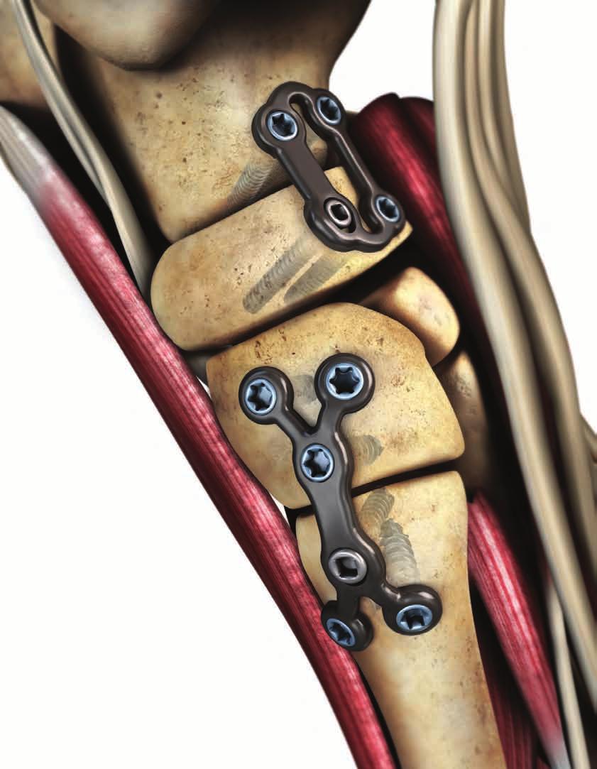
28 Single Joint Fusion Technique: Compression Fusion Plate Closed Compression Fusion Plate The A.L.P.S. Single Joint Fusion Plates (SJF) are made of a titanium alloy (Ti6Al4V) with a TiMAX treatment for increased fatigue strength compared to the standard alloy. The low-profile anatomic design (2 mm) and recessed screw heads minimize possible irritation to the soft tissue and skin. The Single Joint Fusion family of plates contain two unique plate designs of various sizes. Each plate offers up to 1.25 mm of compression and both designs provide the benefits of locking technology. The Single Joint Fusion family of plates offer numerous screw options consisting of 4.0 mm Cancellous Locking, 3.5 mm Cortical Locking, 3.5 mm Multi-Directional Locking, 2.7 mm Cortical Locking, and 3.5 mm Low Profile Non-Locking Screws. 22


29 Compression Fusion Plate Slotted holes provide approximately 1.25 mm compression per hole when used in conjunction with 3.5 mm Low Profile Non-Locking Screw Central region of the plate is contourable along the long axis Threaded holes accept locking 2.7 mm, 3.5 mm, 4.0 mm, and 3.5 mm Multi- Directional Screws as well as 3.5 mm Low Profile Non-Locking Screws 4.0 mm Cancellous Screw 3.5 mm Multi-Directional Locking Screws allow for up to a 30 degree cone of angulation TiMAX for strength, biocompatibility and enhanced imaging capabilities over Stainless Steel F.A.S.T. Guide adapter for provisional fixation through F.A.S.T. Guide F.A.S.T. Guide inserts for easy accurate drilling F.A.S.T. Tabs are designed to allow for bending in multiple planes Screw heads are recessed into the plate providing an overall low profile construct with either Locking or Non-Locking Screws 23


30 Closed Compression Fusion Plate Slotted holes provide approximately 1.25 mm compression per hole when used in conjunction with 3.5 mm Low Profile Non-locking Screw 3.5 mm Cortical Locking Screw TiMAX for strength, biocompatibility and enhanced imaging capabilities over Stainless Steel 4.0 mm Cancellous Locking Screw Closed Box design provides strength Threaded holes accept locking 2.7 mm, 3.5 mm, 4.0 mm, and 3.5 mm Multi- Directional Screws as well as 3.5 mm Low Profile Non-Locking Screws 3.5 mm Multi-Directional Locking Screws allow for up to a 30 degree cone of angulation F.A.S.T. Guide adapter for provisional fixation through F.A.S.T Guide F.A.S.T. Tabs are designed to allow for bending in multiple planes F.A.S.T. Guide inserts for easy accurate drilling Screw heads are recessed into the plate providing an overall low profile construct with either locking or non-locking screws 24

31 Approach and Plate Placement Perform a longitudinal incision either medially or dorsally over the 1st metatarso-cuneiform joint. Expose the joint and denude all cartilage surfaces to expose the bleeding subchondral bone. To avoid shortening and elevation of the metatarsal, place bone graft within the arthrodesis site. A guide pin may be needed to reduce the prepared joint surfaces prior to plate placement. Step 1: Plate Placement The plate should be positioned such that the joint line is located between the center two holes of the plate to ensure that screws are sufficiently clear of the joint line prior to screw insertion. (Step 1) Plate placement Step 1 Note : The Compression Fusion Bending Templates (Cat. No ) and Closed Fusion large (Cat. No ) and small (Cat. No ) Bending Templates can be useful in determining plate to bone contouring prior to inserting the plate onto the bone. 25
 Note : Provisional fixation with the 2.0 mm F.A.S.T. Guide adapter and 2.")

32 Provisional Fixation Step 2: Provisional Fixation For provisional fixation, the 2.0 mm F.A.S.T. Guide adapters (Cat.No ) can convert any F.A.S.T. Guide into a K-wire fixation hole. (Step 2) Note : Provisional fixation with the 2.0 mm F.A.S.T. Guide adapter and 2.0 mm K-wire has the added advantage of allowing the surgeon to predict the trajectory of a locking screw construct under fluoroscopy. Provisional fixation using 2.0 F.A.S.T. Guide adapter and a 2.0 mm K-wire Step 2 If the trajectory is deemed inadequate, the surgeon has several options; bend the plate intra-operatively, employ a 3.5 mm Multi-Directional Screw, or use a 3.5 Low-Profile Non-Locking Screw to establish a new trajectory. Suggestion: Using fluoroscopic guidance to position the single joint fusion family of plates can be especially helpful to ensure adequate purchase of both the Locking and Compression screws in the cuneiform and metatarsal bones. (Figure 1) Fluoroscopic guidance for proper plate placement Figure 1 26
.")


33 In Situ Contouring Step 3: In Situ Contouring With the plate provisionally attached to bone, it is possible to intra-operatively contour the plate to establish a more patient specific fit using the Foot- Multi Planar Bender (Cat No ). (Step 3) Note: The Foot Multi-Planar Benders are double sided for use with a variety of bending techniques. The end with three teeth, shown in Figure 1a, allows for bending in multiple planes. The opposite round end, is used for single plane bending or twisting, as shown in the locked fusion plate in Figure 2. Multi-planar intra-operative contouring for true plate-to-bone fit Step 3 Double F.A.S.T. Guide benders can be used to bend the center of the plate along a single axis Figure 2 Bender end with three teeth shown bending the tab Figure 1a Place the round end of the bender into the F.A.S.T. Guides of adjacent nodes. Hold the bender fixed with the round end as an anchor and manipulate the other end with either side of the benders to bend or twist along a single axis. Figure 1b Caution: Each bend should be in one direction only; reverse or repeated bending may weaken or cause plate to break. 27


.")
34 Screw Insertion Step 4: Screw Insertion To ensure adequate load distribution, all screw holes should be filled according to the screw insertion technique section of this guide. If a combination of Locking and Non-Locking Screws will be used, Non-Locking Screws should be inserted first to secure the plate snugly to bone (HYBRID LOCKING). (Step 4) Note: A detailed technique for screw insertion can be found in the screw section of this technique guide. Insert screws in all screw holes Step 4 28


35 Closed Compression Fusion Plate F.A.S.T. Tabs are designed to allow for bending in multiple planes Caution: Each bend should be in one direction only; reverse or repeated bending may weaken or cause plate to break. 29
 (MDS) Multi-Directional Diameter Options 3.5 mm (Cat No. 8161-35-0XX) 4.0 mm (Cat. No. 8161-40-0XX) 2.")
36 Single Joint Fusion Plates Compression Fusion Plate Closed Compression Fusion Plate 42 mm 26.5 mm 30.5 mm 18.5 mm 17.5 mm 16.5 mm 2mm 2mm 2mm Specifications & Screw Options Screw Type Locking Non-Locking (Low Profile) (MDS) Multi-Directional Diameter Options 3.5 mm (Cat No XX) 4.0 mm (Cat. No XX) 2.7 mm (Cat. Nol XX) 3.5 mm (Cat. No XX) 3.5 mm (Cat. No XX) Drill Bit Handle Driver Depth Gauge Length Options 2.7 mm Calibrated Drill Bit (Cat No ) Torque Limiting (Cat No ) T-15 tapered (Cat No ) Small Frag (LOCK line) (Cat No ) 2.7 mm Drill Meas Sleeve (Cat No ) 2.0 mm Marked Drill Bit Short (Cat No ) Torque Limiting (Cat No ) T-15 tapered (Cat No ) Small Frag (LOCK line) (Cat No ) 2.0 mm Drill Meas Sleeve Short (Cat No ) 2.5 mm Drill Bit (Cat No ) Ratcheting Handle (Cat No ) 2.2 mm Square (Cat No ) Small Frag (NON-L line) (Cat No ) 2.7 mm Calibrated Drill Bit (Cat No ) Ratcheting Handle (Cat No ) 2.2 mm Square (Cat No ) Small Frag (LOCK line) (Cat No ) mm mm mm mm 30

37 R E C O N LATERAL COLUMN LENGTHENING These are images of models with bones shown with plates in place and not real patients. They are provided to show positioning and not intended to suggest immediate weight bearing.
38 R E C O N LATERAL COLUMN LENGTHENING

39
40 Lateral Column Lengthening Plate Technique: Calcaneal Cuboid Joint Calcaneal Osteotomy The A.L.P.S. Lateral Column Lengthening Plates (LCLP) are made of a titanium alloy (Ti6Al4V) with a TiMAX treatment for increased fatigue strength compared to the standard alloy. The Lateral Column Lengthening plates are designed to be used with either calcaneal osteotomy or calcaneocuboid arthrodesis lengthening procedures. The implants are available in four different sizes - a no wedge, 8 mm wedge, 10 mm wedge or 12 mm wedge. The low-profile anatomic design (2 mm) and recessed screw heads minimize possible irritation of the peroneal tendons and skin. In addition, the plate s profile has been designed with multiple radii of curvature to further minimize the possibility of tendon irritation. The wedges are tapered dorsal to plantar to minimize the possibility of an unnatural tilt of the cuboid. The wedges are also tapered laterally to medially for a more anatomically correct wedge shape.the wedge plates have also been designed to maintain ample space for the application of bone graft materials. 32


41 Lateral Column Lengthening Plate Screw heads are recessed into the plate providing an overall low profile construct with either Locking or Non-Locking Screws TiMAX for strength, biocompatibility and enhanced imaging capabilities over Stainless Steel Low profile 2 mm thickness reduces possibility of tendon and soft tissue irritation Threaded holes accept locking 2.7 mm, 3.5 mm, 4.0 mm, and 3.5 mm Multi-Directional Screws as well as 3.5 mm Low Profile Non-Locking Screws 3.5 mm Multi-Directional Locking Screws allow for up to a 30 degrees cone of angulation Four different sizes to choose from: no wedge, 8 mm wedge, 10 mm wedge or 12 mm wedge Wedges have a dorsal to plantar taper F.A.S.T. Guide adapter for provisional fixation through F.A.S.T. Guide no wedge wedge Lateral to medial wedge taper for a more anatomically correct shape F.A.S.T. Guide inserts for easy accurate drilling 33


42 Approach and Plate Placement The following surgical technique applies to the Evans lateral column lengthening osteotomy. This general technique can also be applied to other lateral column lengthening procedures of the foot such as a calcaneocubiod joint distraction for a lateral column lengthening procedure. Step 1: Approach Make an oblique incision, just proximal to the calcaneocuboid joint and 1 cm below the tip of the fibula. Take care to avoid the intermediate dorsal cutaneous and sural nerves and to protect and retract the peroneal tendons. Using a blunt retractor, continue dissection and exposure with the release of dorsal and plantar soft tissue from the planned osteotomy site. Step 2: Osteotomy and Plate Placement The T-15 driver inserted in the wedge plate center to aid plate positioning and wedge insertion between bone segments Step 2 Next, perform the osteotomy usually 1 to 1.2 cm proximal to the calcaneocuboid joint. With the osteotomy properly distracted to between 8 and12 mm, choose the appropriate plate. If the lateral column lengthening wedge plate is used, ensure that the wedge sides are in close contact with either side of the joint surface. (Step 2) The T-15 Taper driver (Cat. No ) can be used in to aid in plate insertion. (Step 2) Note: The widest portion of the wedge should be placed dorsally to minimize the possibility of an unnatural tilt of the cuboid. Note: The Lateral Column Lengthening family of plates are not designed with flexible plating technology. Therefore, the F.A.S.T. Guide inserts are intended for fast and accurate drilling purposes only and cannot be used for bending purposes. 34
 can convert any F.A.S.T. Guide into a K-wire fixation hole.")


43 Provisional Fixation Step 3: Provisional Fixation For provisional fixation, the 2.0 mm F.A.S.T Guide adapters (Cat.No ) can convert any F.A.S.T. Guide into a K-wire fixation hole. (Step 3) Note: Provisional fixation has the added advantage of allowing the surgeon to accurately predict the trajectory of a locking screw construct under fluoroscopic guidance. (Figure 1) If a trajectory is deemed inadequate (figure 1), the surgeon has two options; employ a 3.5 Low-Profile Non-Locking Screw or a 3.5 mm Multi-Directional Screw as demonstrated in Figure 2. Provisional plate fixation Step 3 Ensure proper trajectories under fluoroscopic guidance Figure 1 Positioning of the Multi-Directional Screw off center to avoid the joint space Figure 2 35
 Step 4: Screw Insertion Removal of F.A.S.T.")


44 Screw Insertion Note: It is helpful to have two points of fixation prior to attempting to remove F.A.S.T. Guides from the lateral column. (Figure 1) Step 4: Screw Insertion Removal of F.A.S.T. Guides Figure 1 If a combination of locking and non-locking screws will be used, Non-Locking Screws should be inserted first to secure the plate in close apposition to bone. All screw holes should be filled to ensure adequate load distribution of the locking construct and plate to bone fixation. (Step 4) Note: The trajectories of the locking holes in the plate are designed not to interact at lengths up to 26 mm. In addition, the trajectories aim away from the plate center, helping to avoid screws passing through the joint or osteotomy site. (Figure 2) Screw trajectories are designed to reduce the potential for interaction with joint or osteotomy site Figure 2 Note: A detailed technique for screw insertion can be found in the screw section of this technique guide. Insert screws in all screw holes Step 4 36
45 Lateral Column Lengthening Plate LCLP No Wedge LCLP Small LCLP Medium LCLP Large 8 mm 10 mm 12 mm 17 mm 12 mm 12 mm 12 mm 25 mm 2 mm 6 mm 8 mm 10 mm 25 mm 28 mm 29 mm Note: No Wedge plate profile, length and width matches LCLP Small plate size. 4.5 mm 4.5 mm 4.5 mm Specifications & Screw Options Screw Type Locking Non-Locking (Low Profile) (MDS) Multi-Directional Diameter Options 3.5 mm (Cat No XX) 4.0 mm (Cat. No XX) 2.7 mm (Cat. Nol XX) 3.5 mm (Cat. No XX) 3.5 mm (Cat. No XX) Drill Bit Handle Driver Depth Gauge Length Options 2.7 mm Calibrated Drill Bit (Cat No ) Torque Limiting (Cat No ) T-15 tapered (Cat No ) Small Frag (LOCK line) (Cat No ) 2.7 mm Drill Meas Sleeve (Cat No ) 2.0 mm Marked Drill Bit Short (Cat No ) Torque Limiting (Cat No ) T-15 tapered (Cat No ) Small Frag (LOCK line) (Cat No ) 2.0 mm Drill Meas Sleeve Short (Cat No ) 2.5 mm Drill Bit (Cat No ) Ratcheting Handle (Cat No ) 2.2 mm Square (Cat No ) Small Frag (NON-L line) (Cat No ) 2.7 mm Calibrated Drill Bit (Cat No ) Ratcheting Handle (Cat No ) 2.2 mm Square (Cat No ) Small Frag (LOCK line) (Cat No ) mm mm mm mm 37
46 38

47 R E C O N MEDIAL COLUMN FUSION These are images of models with bones shown with plates in place and not real patients. They are provided to show positioning and not intended to suggest immediate weight bearing.
48 R E C O N MEDIAL COLUMN FUSION

49
50 Medial Column Fusion Technique: The A.L.P.S. Medial Column Fusion Plate (MCF) is made of titanium alloy (Ti6Al4V) with a TiMAX treatment for increased fatigue strength compared to the standard alloy. It has an anatomical shape corresponding to the anatomy of the navicular, medial cuneiform and first metatarsal. The low-profile anatomic design (2 mm) and recessed screw heads minimize potential irritation of the ligaments and soft tissue. In addition to the specific anatomic design, strategic regions of the plate permit the user to contour the plate to bone after provisional fixation to match variations in individual patient anatomy. The implant is designed to provide up to 1.25 mm of compression in both the naviculo-cuneiform and tarso-metatarsal joints. The Medial Column Fusion (MCF) plate offers numerous screw options; 4.0 mm Cancellous Locking, 3.5 mm Cortical Locking, 3.5 mm Multi-Directional Locking, 2.7 mm Cortical Locking, and 3.5 mm Low Profile Non-Locking Screws. 40


51 Medial Column Fusion Plate TiMAX for strength, biocompatibility and enhanced imaging capabilities over Stainless Steel Additional tabs on the Dorsal aspect of the Medial Column Fusion plate provide additional points of fixation and can be contoured in three planes with the Foot-Multi Planar Bender Screw heads are recessed into the plate providing an overall low profile construct with either locking or non-locking screws Closed Box design provides strength Threaded holes accept locking 2.7 mm, 3.5 mm, 4.0 mm, and 3.5 mm Multi-Directional Screws as well as 3.5 mm Low Profile Non-Locking Screws 3.5 mm Multi-Directional Locking Screws allow for up to a 30 degree cone of angulation Unidirectional compression slots provide approximately 1.25 mm compression per hole when used in conjunction with 3.5 mm Low Profile Non-Locking Screw Left (Lime) F.A.S.T. Guide adapter for provisional fixation through F.A.S.T. Guide F.A.S.T. Tabs are designed to allow for bending in multiple planes F.A.S.T. Guide inserts for easy accurate drilling Right (Rose) Double F.A.S.T. Guide benders allow for bending along one plane 41

52 Approach and Plate Placement Step 1: Exposure Perform a longitudinal incision medially extending from the proximal border of the navicular to the shaft of the first metatarsal. Expose and denude the cartilage surfaces of both the naviculo-cuneiform and the tarso-metatarsal joints, exposing the bleeding subchondral bone. To avoid shortening and elevation of the first ray, place adequate bone graft within the arthrodesis site. A guide pin may be used to maintain bony alignment prior to plate placement. Note: Depending on surgeon preference and exposure of the anterior tibial tendon, the surgeon has two options; resect and reattach the tendon after plate placement or dissect and spare the tendon by sliding the plate under the anterior tibial tendon. If the anterior tibial tendon is dissected and spared, it is recommended to pre-contour the plate and remove the 5 most distal F.A.S.T. Guides prior to inserting the plate beneath the tendon. Step 2: Plate Placement Plate placement Step 2 The plate should be positioned medially and extend from the navicular, across the medial cuneiform to the first metatarsal. If compression is desired, care should be given to ensure that the two unidirectional compression slots are located within the medial cuneiform and the first metatarsal, and that the screws are sufficiently clear of the joint line prior to screw insertion. 42

 when bending in multiple planes. Note: The Double F.A.S.T. Guide Benders are double sided for use in various bending techniques.")

53 Plate Contouring Step 3: Plate Contouring Suggestion: Precontouring the Medial Column Fusion Plate can be difficult. Therefore, it is helpful to obtain the general anatomic profile of the medial surfaces of navicular, medial cuneiform and first metatarsal bones using the Medial Column Fusion bending template (Cat.No ). (Step 3a) With the template removed, match the anatomic profile with the Medial Column Fusion plate using either the Double FAST Guide Benders (Cat.No ) for bending along a single plane or Multi Planer benders (Cat.No ) when bending in multiple planes. Note: The Double F.A.S.T. Guide Benders are double sided for use in various bending techniques. The boxed end, shown in Step 3a, allows for convex bending in one plane. The opposite end, with a slit and post, is used for concave single plane bending. Convex uni planar bending using the Double F.A.S.T. Guide Bender Step 3a Caution: Each bend should be in one direction only; reverse or over bending may weaken or cause plate to break. Concave uni planar bending using the reverse bending nodes of the Double F.A.S.T. Guide Bender Step 3b 43
 Note: Provisional fixation with the 2.0 mm F.A.S.T. Guide adapter and 2.")


54 Provisional Fixation Step 4: Provisional Fixation For provisional fixation, the 2.0 mm F.A.S.T. Guide adapters (Cat.No ) can convert any F.A.S.T. Guide into a K-wire fixation hole. (Step 4) Note: Provisional fixation with the 2.0 mm F.A.S.T. Guide adapter and 2.0 mm K-wire has the added advantage of allowing the surgeon to accurately predict the trajectory of a locking screw construct under fluoroscopy. Provisional fixation with the 2.0 mm F.A.S.T. Guide adapter and 2.0 mm K-wire Step 4 If the trajectory is deemed inadequate, the surgeon has several options; bend the plate intra-operatively, employ a 3.5 mm Multi-Directional Screw, or use a 3.5 Low-Profile Non-Locking Screw to establish a new trajectory. Suggestion: Using fluoroscopic guidance to position the Medial Column Fusion plate can be especially helpful to ensure that the Unidirectional Compression Slots are within the boarders of the medial cuneiform and first metatarsal bones while still maintaining adequate purchase within the navicular bone. (Figure 1) Fluoroscopic guidance can be used to position the Medial Column Fusion plate Figure 1 Insertion of a 3.5 mm Multi-Directional Screw in order to avoid the talonavicular joint Figure 2 Note: Natural variations in the navicular bone make identifying screw trajectories especially important when positioning the medial column fusion plate. It is often necessary assess the trajectory of the most posterior inferior screw and insert a 3.5 mm Multi- Directional Screw in order to avoid the talonavicular joint. (Figure 2) 44
. (Step 5) Caution: Each bend should be in one direction only; reverse or over bending may weaken or cause plate to break.")
55 In Situ Contouring Step 5: Contour To Bone With the plate provisionally fixed, it is also possible to further contour the plate to bone for a more patient specific fit using the Foot-Multi Planar Bender (Cat No ). (Step 5) Caution: Each bend should be in one direction only; reverse or over bending may weaken or cause plate to break. The Foot Multi-Planar Benders are double sided for use in various bending techniques. The end with three teeth allows for bending in multiple planes. The opposite end, is used for single plane bending or twisting. Step 5 45
56 Screw Insertion (Locking and Non-Locking) Step 6: Screw Insertion (Locking and Non-Locking) To obtain up to 1.25 mm of compression across both the naviculo-cuneiform and tarso-metatarsal joints using the Medial Column Fusion Plate, sequentially fix and compress each joint beginning with the naviculocuneiform joint using the following series of steps. Reduce and fix the the plate to the navicular bone by: First, placing a Non-Locking Screw in the center hole of the navicular section. Next, fix the plate to the navicular bone by obtaining at least two cortices of fixation with the remaining locking screw holes. Step 6a Note: A detailed technique for screw insertion can be found in the screw section of this technique guide. 4 5 Compress the naviculocuneiform joint by fully inserting a 3.5 mm Non-Locking Screw in the unidirectional compression slot located over the medial cuneiform Step 6b 7 6 Fix the plate to the medial cuneiform by obtaining at least two corticies of fixation with the locking screws. Step 6c 46


57 Fix the plate to the metatarsal by obtaining at least two corticies of fixation with the locking screws. Step 6e 8 9 Compress the Tarsometatarsal joint by fully inserting a 3.5 mm Non-Locking Screw in the unidirectional compression slot located over the 1st metatarsal Step 6d
 2.7 mm (Cat. No. 8163-27-0XX) 3.5 mm (Cat. No. 1312-18-0XX) 3.5 mm (Cat. No. 8163-35-0XX) Drill Bit Handle Driver Depth Gauge Length Options 2.")
58 Medial Column Fusion Plate 27 mm 64 mm 2 mm Specifications & Screw Options Screw Type Locking Non-Locking (Low Profile) (MDS) Multi-Directional Diameter Options 3.5 mm (Cat No XX) 4.0 mm (Cat. No XX) 2.7 mm (Cat. No XX) 3.5 mm (Cat. No XX) 3.5 mm (Cat. No XX) Drill Bit Handle Driver Depth Gauge Length Options 2.7 mm Calibrated Drill Bit (Cat No ) Torque Limiting (Cat No ) T-15 tapered (Cat No ) Small Frag (LOCK line) (Cat No ) 2.7 mm Drill Meas Sleeve (Cat No ) 2.0 mm Marked Drill Bit Short (Cat No ) Torque Limiting (Cat No ) T-15 tapered (Cat No ) Small Frag (LOCK line) (Cat No ) 2.0 mm Drill Meas Sleeve Short (Cat No ) 2.5 mm Drill Bit (Cat No ) Ratcheting Handle (Cat No ) 2.2 mm Square (Cat No ) Small Frag (NON-L line) (Cat No ) 2.7 mm Calibrated Drill Bit (Cat No ) Ratcheting Handle (Cat No ) 2.2 mm Square (Cat No ) Small Frag (LOCK line) (Cat No ) mm mm mm mm 48

59 R E C O N DORSAL MIDFOOT FUSION- SMALL/LARGE These are images of models with bones shown with plates in place and not real patients. They are provided to show positioning and not intended to suggest immediate weight bearing.
60 R E C O N DORSAL MIDFOOT FUSION- SMALL/LARGE

61
62 Dorsal Mid-Foot Fusion Technique: The A.L.P.S. Dorsal Mid-Foot Fusion Plate (DMFP) is made of titanium alloy (Ti6Al4V) with a TiMAX treatment for increased fatigue strength compared to the standard alloy. The plate is designed to fit the specific anatomic profile of the mid foot and is available in two different sizes; the small plate is designed to compress and fuse two tarsometatarsal joints, the large plate fuses two tarsometatarsal joints and has additional locking tabs for fusing the Naviculocuneiform joint. The closed box design provides strength while the integrated window improves joint access for placement of bone graft within the arthrodesis site and improved postoperative visualization on x-ray versus a solid plate. The low-profile anatomic design (2 mm) and recessed screw heads minimize possible irritation of the ligaments and soft tissue. In addition to the specific anatomic design, strategic regions of the plate permit the user to contour the plate on bone with specially designed bending irons to match variations in individual patient anatomy. Each unidirectional compression slot provides up to 1.25 mm of compression and is available in both the small and large plate options (maximum compression 2.5 mm). The plate offers numerous screw options including: 4.0 mm Cancellous Locking, 3.5 mm Cortical Locking, 3.5 mm Multi-Directional Locking, 2.7 mm Cortical Locking, and 3.5 mm Low Profile Non-Locking Screws. 50


63 Dorsal Mid-Foot Fusion Plate Closed Box design provides strength Threaded holes accept locking 2.7 mm, 3.5 mm, 4.0 mm, and 3.5 mm Multi- Directional Screws as well as 3.5 mm Low Profile Non-Locking Screws TiMAX for strength, biocompatibility and enhanced imaging capabilities over Stainless Steel Additional tabs on the Dorsal Midfoot Fusion Large provide additional points of fixation for the navicular bone and can be contoured in three planes with the Foot-Multi Planar Bender Screw heads are recessed into the plate providing an overall low profile construct with either Locking or Non-Locking Screws 3.5 mm Multi-Directional Locking Screws allow for up to a 30 degree cone of angulation Unidirectional compression slots provide approximately 1.25 mm compression per hole when used in conjunction with 3.5 mm Low Profile Non-Locking Screw F.A.S.T. Guide adapter for provisional fixation through F.A.S.T. Guide F.A.S.T. Tabs are designed to allow for bending in multiple planes F.A.S.T. Guide inserts for easy accurate drilling Double F.A.S.T. Guide Benders allow for bending along two axes 51


64 Approach and Plate Placement The following surgical technique applies to the fusion of the 2nd and 3rd tarsometatarsal joints. This general technique can also be applied to the fusion of the 1st and 2nd tarsometatarsal joints or for the fixation of a Lisfranc dislocation or fracture. Step 1: Exposure Positioning the Small Dorsal Midfoot Fusion plate over the 2nd and 3rd Metatarsal joints Step 2 Perform a longitudinal incision over the 3rd metatarso-cuneiform joint. Expose the 2nd and 3rd metatarso-cuneiform joints and denude all cartilage surfaces exposing the bleeding subchondral bone. To avoid shortening and elevation of the metatarsals place bone graft within the arthrodesis site. Step 2: Plate Placement Both the large and small Dorsal Midfoot Fusion plates are tapered proximal to distal, the widest segment should be positioned over the cuneiforms with the more narrow distal segment positioned over the metatarsals. Care should be taken to position the plate such that the joint lines are located between the holes of the plate, to ensure screws are sufficiently clear of the joint line prior to screw insertion. (Step 2) Fluoroscopic guidance to position the Small Dorsal Midfoot Fusion plate Figure 1 Suggestion: Using fluoroscopic guidance to position the Small Dorsal Midfoot Fusion plate can be especially helpful to ensure adequate purchase of both the locking screws and compression screws in the cuneiform and metatarsal bones. (Figure 1) Using fluoroscopic guidance to position the Large Dorsal Midfoot Fusion plate ensures that the navicular tabs are adequately centered within the navicular bone while maintaining proper alignment of the distal locking holes and compression slots within the 2nd and 3rd metatarsals. 52
. (Step 3a) Note: The Double F.A.S.T. Guide Benders are double sided for use in various bending techniques. The boxed end, shown in Step 3a, allows for concave bending in one plane.")

65 Contouring Step 3a: Plate Contouring To establish a more patient specific fit, it is possible to contour the large and small Dorsal Midfoot Fusion plates using the Double F.A.S.T. Guide Bender (Cat No ). (Step 3a) Note: The Double F.A.S.T. Guide Benders are double sided for use in various bending techniques. The boxed end, shown in Step 3a, allows for concave bending in one plane. The opposite end, with a slit and post, is used for convex single plane bending across a single bridge. Step 3b: Tab Contouring With the plate provisionally fixed to bone, it is possible to contour the tabs of the Large Dorsal Midfoot Fusion plate in multiple planes using the Foot-Multi Planar Bender (Cat No ) and the Double F.A.S.T. Guide Bender (Cat No ). (Step 3b) Intraoperative contouring with Double F.A.S.T. Guide Bender for true plate to bone fit Step 3a Note: The Foot Multi-Planar Benders are double sided for use in various bending techniques. The bender end with three teeth, shown in Step 3b, allows for bending in multiple planes. The opposite end of the bender is used for single plane bending. Caution: Each bend should be in one direction only; reverse or over bending may weaken or cause plate to break. Note: The Dorsal Midfoot Fusion Small Template (Cat. No ) and Dorsal Midfoot Fusion Large Template (Cat. No ) can be useful in assessing the plate to bone contour prior to inserting the plate onto the bone. Multi-planar intraoperative contouring for true plate-to-bone fit Step 3b 53


66 Provisional Fixation Step 4: Provisional Fixation For provisional fixation, the 2.0 mm F.A.S.T. Guide adapters (Cat.No ) can convert any F.A.S.T. Guide into a K-wire fixation hole. Suggestion: Obtaining two points of provisional fixation with the F.A.S.T. Guide adapters has the added advantage of allowing the surgeon to accurately predict the trajectory of a locking screw construct under fluoroscopic guidance. If a trajectory is deemed inadequate, the surgeon has two options; employ a 3.5 mm Multi- Directional Screw or utilize a 3.5 Low-Profile Non-Locking screw. Provisional plate fixation Step 4 Accurately predict the trajectory of a locking screw construct under fluoroscopic guidance Step 4 54

 Place the 2.5mm end of the 2.")
 eccentrically in the narrowest portion of the unidirectional slot and drill through both")
 Identify the")
67 Screw Insertion (Non-Locking, Compression) Step 5: Non-Locking Screw Insertion (Compression) To obtain maximum compression with the Small Dorsal Midfoot Fusion Plate, partially insert 3.5 mm Low Profile Non-Locking screws into all four of the unidirectional compression slots using the following series of steps. Step 5a: Non-Locking Screw Insertion (Compression) Place the 2.5mm end of the 2.5/3.5 mm Drill Guide (Cat.No ) eccentrically in the narrowest portion of the unidirectional slot and drill through both cortices using the 2.5 mm Drill Bit (Cat.No ). Eccentric drill guide placement Step 5a Step 5b: Non-Locking Screw Insertion (Compression) Identify the appropriate screw length by using the Small Fragment Depth Gauge (Cat.No ) and taking a direct reading from the NON-L (Non-Locked) line. Identify screw length Step 5b 55
 being careful not to engage the screw head with the plate.")
 Next, fully insert each 3.5 mm Low Profile Non-Locking Screw one by one.")
68 Screw Insertion (Non-Locking, Compression) Step 5C: Non-Locking Screw Insertion (Compression) Partially advance the screw using the black ratchet handle (Cat. No ) with the 2.2 mm Square Driver (Cat. No ) being careful not to engage the screw head with the plate. Partially insert screw Step 5c Step 5d: Non-Locking Screw Insertion (Compression) Once each unidirectional compression slot is filled with a partially inserted 3.5 mm Low Profile Non- Locking Screw: First, remove all provisional fixation components. (Step 5d) Next, fully insert each 3.5 mm Low Profile Non-Locking Screw one by one. (Step 5e) Partially inserted compression screws Step 5d Note: A detailed technique for screw insertion can be found in the screw section of this technique guide. Fully inserted compression screws Step 5e 56


69 Screw Insertion (Locking) Step 6 Fill the remaining locking holes with locking screws in each corner to complete the locking construct. (Step 6) Note: A detailed technique for screw insertion can be found in the screw section of this technique guide. Remaining locking screws installed in the small plate Step 6 Remaining locking screws installed in the large plate Step 6 57
 (MDS) Multi-Directional Diameter Options 3.5 mm (Cat No. 8161-35-0XX) 4.0 mm (Cat. No. 8161-40-0XX) 2.7 mm (Cat. Nol. 8163-27-0XX) 3.5 mm (Cat. No. 1312-18-0XX) 3.5 mm (Cat. No. 8163-35-0XX) Drill Bit Handle Driver Depth Gauge Length Options 2.")
 2.0 mm Marked Drill Bit Short (Cat No. 2142-88-008) Torque Limiting (Cat No. 2141-18-001) T-15 tapered (Cat No. 2142-15-070) Small Frag (LOCK line) (Cat No. 2142-35-100) 2.")
70 Dorsal Midfoot Fusion Plates Dorsal Midfoot Fusion Large Plate Dorsal Midfoot Fusion Small Plate 24 mm 27 mm 54 mm 37 mm 2 mm 2 mm Specifications & Screw Options Screw Type Locking Non-Locking (Low Profile) (MDS) Multi-Directional Diameter Options 3.5 mm (Cat No XX) 4.0 mm (Cat. No XX) 2.7 mm (Cat. Nol XX) 3.5 mm (Cat. No XX) 3.5 mm (Cat. No XX) Drill Bit Handle Driver Depth Gauge Length Options 2.7 mm Calibrated Drill Bit (Cat No ) Torque Limiting (Cat No ) T-15 tapered (Cat No ) Small Frag (LOCK line) (Cat No ) 2.7 mm Drill Meas Sleeve (Cat No ) 2.0 mm Marked Drill Bit Short (Cat No ) Torque Limiting (Cat No ) T-15 tapered (Cat No ) Small Frag (LOCK line) (Cat No ) 2.0 mm Drill Meas Sleeve Short (Cat No ) 2.5 mm Drill Bit (Cat No ) Ratcheting Handle (Cat No ) 2.2 mm Square (Cat No ) Small Frag (NON-L line) (Cat No ) 2.7 mm Calibrated Drill Bit (Cat No ) Ratcheting Handle (Cat No ) 2.2 mm Square (Cat No ) Small Frag (LOCK line) (Cat No ) mm mm mm mm 58

71 T R A U M A LOCKING CALCANEAL These are images of models with bones shown with plates in place and not real patients. They are provided to show positioning and not intended to suggest immediate weight bearing.
72 T R A U M A LOCKING CALCANEAL

73
74 Locking Calcaneal Plate Technique: The A.L.P.S. Locking Calcaneal Plate is made of a titanium alloy (Ti6Al4V) with a TiMAX treatment for increased fatigue strength compared to the standard alloy. This locking plate offers a high strength, low profile design that closely matches the anatomy of the calcaneus. The anatomical shape of the plate is further enhanced by pre-described screw trajectories corresponding to the anatomy of the subtalar joint. The plate is available in two different sizes with right and left options. Its thickness is 2.5 mm, with reduced bridge thickness between screws to facilitate contouring to the bone. The prescribed trajectory of the most superior locking screw is angled downward to closely match the geometry of the articular surface for subarticular support while minimizing the potential of penetrating the posterior articular facet. The two adjacent locking screws have trajectories that angle superiorly into the sustentaculum to support the middle facet. The plate offers numerous screw options including: 4.0 mm Cancellous Locking, 3.5 mm Cortical Locking, 3.5 mm Multi-Directional Locking, 2.7 mm Cortical Locking, and 3.5 mm Low Profile Non-Locking Screws. 60


 Offered in right and left with large and small size options Right")
75 Locking Calcaneal Plate 3.5 mm Multi-Directional Locking Screws allow for up to a 30 degree cone of angulation TiMAX for strength, biocompatibility and enhanced imaging capabilities over Stainless Steel Closed Box perimeter design provides strength Pre-contoured anatomical design with screw trajectories corresponding to the anatomy of the subtalar joint Threaded holes accept Locking 2.7 mm, 3.5 mm, 4.0 mm, and 3.5 mm Multi- Directional Screws as well as 3.5 mm Low Profile Non-Locking Screws Screw heads are recessed into the plate providing an overall low profile construct with either Locking or Non-Locking Screws F.A.S.T. Guide adapter for provisional fixation through F.A.S.T. Guide Left (Lime) Offered in right and left with large and small size options Right (Rose) F.A.S.T. Guide inserts for easy accurate drilling F.A.S.T. Tabs are designed to allow for In-Situ Contouring 61

76 Approach, Reduction and Plate Placement Step 1: Approach The calcaneus is approached through an extensile lateral incision which minimizes the sequelae of peroneal tendinitis and devascularization of the anterior skin flap, as well as preserving the sural nerve which should be entirely within the flap. The calcaneo-fibular ligament is taken with the flap. The full thickness flap is then retracted using the no touch technique by the use of three K-wires, one up the fibular shaft, one in the talar neck and one in the cuboid. Next, a short Schanz pin is inserted into the calcaneus at posterior inferior corner of the wound to be used as a handle for subsequent reduction. Reduction and plate placement Step 2 Step 2: Reduction and Plate Placement After adequate exposure and irrigation of hematoma, the fracture should be reduced and provisionally stabilized with K-wires. The subtalar reduction is verified on a fluoroscopic mortise view of the ankle, and again with the foot externally rotated, into the supine position and dorsiflexed. A modified Harris heel view is then obtained to verify that the heel is out of varus. Once reduction is verified, the plate is sized and positioned on the lateral surface such that the most superior F.A.S.T. Guide lies just under the posterior articular facet and the most superior anterior F.A.S.T. Guide is positioned just in line with the anterior superior portion of the anterior articular facet. (Step 2) Final verification of plate size and placement is easily confirmed under fluoroscopy (Figure 1). Plate placement under fluoroscopic X-ray with a direct lateral view Figure 1 Note: The Calcaneal Bending Templates (Small Cat.No ; Large Cat.No ) can be useful in determining plate to bone contouring and size prior to inserting the plate onto the bone. With the template removed, match the anatomic profile using either the Double F.A.S.T. Guide Benders for bending along a single plane or Multi Planer Benders when bending in multiple planes. 62

77 Provisional Fixation Step 3: Provisional Fixation For provisional fixation with a K-wire, the 2.0 mm F.A.S.T Guide adapters (Cat.No ) can convert any F.A.S.T. Guide into a K-wire fixation hole. Provisional fixation has the added advantage of allowing the surgeon to predict the trajectory of a plate/screw construct relative to important articular structures with fluoroscopy. If a trajectory is deemed inadequate, the surgeon has several options; bend the plate intra-operatively, employ a 3.5 mm Multi-Directional Screw, or use a 3.5 Low-Profile Non-Locking Screw to establish a new trajectory. Suggestion: Provisional fixation should be obtained at three points, one in the anterior facet, one in the portion of the plate under the posterior tuberosity and one in the portion of the plate that sits underneath the posterior facet. Provisional fixation should be obtained at three points with F.A.S.T. Guide adapters Step 3 63


78 Non-Locking Screw Insertion Step 4: Non-Locking Screw Fixation With the plate provisionally fixed at three points, exchange the three provisional points of fixation with 3.5 mm Low Profile Non-Locking Screws to reduce the plate to bone. (Step 4) Note: A detailed technique for screw insertion can be found in the Small Frag screw section of this technique guide. The sequential exchange of provisional fixation with Non-Locking fixation ensures that the plate is well reduced to bone Step 4 64
. Note: The Locking Calcaneal Plate is designed to be contoured along a single axis.")
79 In Situ Contouring Step 5: In Situ Contouring With the plate reduced to bone with Non-Locking Screws, it is rarely necessary to further contour the plate. If this is required however, it can be performed using the Foot-Multi Planar Bender (Cat No ). Note: The Locking Calcaneal Plate is designed to be contoured along a single axis. Therefore, only the end of the bender without tabs can be used when contouring or adjusting the plate and screw trajectories. In addition, only one bridge section should be contoured at a time. (Step 5) In Situ Contouring of the plate onto bone Step 5 Caution: Each bend should be in one direction only; reverse or over bending may weaken or cause the plate to break. 65


80 Locking Screw Fixation Step 6: Locking Screw Fixation Additional locking screws can then be placed as needed to secure the fracture. (Step 6) Locking screw fixation Step 6 Note: The anatomical shape of the plate is further enhanced by pre-described screw trajectories corresponding to the anatomy of the subtalar joint line. While the trajectories are directed at the sustentaculum tali, these trajectories can be further refined with either 3.5 mm Multi-Directional Locking Screws or 3.5 mm Low Profile Non-Locking Screws. (Figure 2) Note: A detailed technique for screw insertion can be found in the screw section of this technique guide. Prescribed screw trajectories corresponding to the anatomy of the subtalar joint line and angled toward the Sustentaculum tali Figure 2 66
 4.0 mm (Cat. No. 8161-40-0XX) 2.7 mm (Cat. No. 8163-27-0XX) 3.5 mm (Cat. No. 1312-18-0XX) 3.5 mm (Cat. No. 8163-35-0XX) Drill Bit Handle Driver Depth Gauge Length Options 2.")
 2.0 mm Marked Drill Bit Short (Cat No. 2142-88-008) Torque Limiting (Cat No. 2141-18-001) T-15 tapered (Cat No. 2142-15-070) Small Frag (LOCK line) (Cat No. 2142-35-100) 2.")
81 Locking Calcaneal Plate Small Large 36 mm 37 mm 60 mm 67 mm 2.5 mm 2.5 mm 1.5 mm Specifications & Screw Options Screw Type Locking Non-Locking (Low Profile) (MDS) Multi-Directional Diameter Options 3.5 mm (Cat No XX) 4.0 mm (Cat. No XX) 2.7 mm (Cat. No XX) 3.5 mm (Cat. No XX) 3.5 mm (Cat. No XX) Drill Bit Handle Driver Depth Gauge Length Options 2.7 mm Calibrated Drill Bit (Cat No ) Torque Limiting (Cat No ) T-15 tapered (Cat No ) Small Frag (LOCK line) (Cat No ) 2.7 mm Drill Meas Sleeve (Cat No ) 2.0 mm Marked Drill Bit Short (Cat No ) Torque Limiting (Cat No ) T-15 tapered (Cat No ) Small Frag (LOCK line) (Cat No ) 2.0 mm Drill Meas Sleeve Short (Cat No ) 2.5 mm Drill Bit (Cat No ) Ratcheting Handle (Cat No ) 2.2 mm Square (Cat No ) Small Frag (NON-L line) (Cat No ) 2.7 mm Calibrated Drill Bit (Cat No ) Ratcheting Handle (Cat No ) 2.2 mm Square (Cat No ) Small Frag (LOCK line) (Cat No ) mm mm mm mm 67
82 68

83 T R A U M A NAVICULAR FRACTURE These are images of models with bones shown with plates in place and not real patients. They are provided to show positioning and not intended to suggest immediate weight bearing.
84 T R A U M A NAVICULAR FRACTURE

85
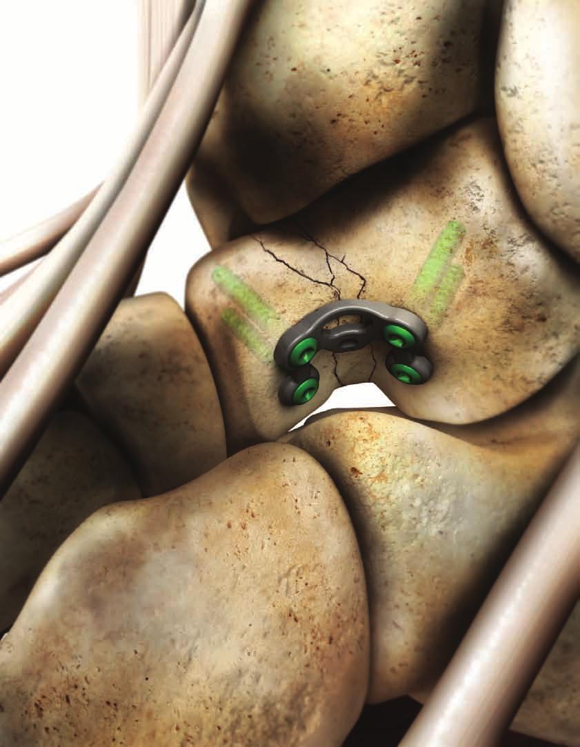
86 Navicular Fracture Plate Technique: The A.L.P.S. Navicular Fracture Plates (NFP) are made of a titanium alloy (Ti6Al4V) with a TiMAX treatment for increased fatigue strength compared to the standard alloy. The low-profile anatomic design (1.5 mm thickness) and uniform plate screw construct minimize potential irritation of the ligaments and soft tissue. The Navicular Fracture Plate has been precontoured to closely match the natural anatomy of the navicular bone. In addition to the specific anatomic design, strategic regions of the plate permit the user to intra-operatively contour the plate to match variations in individual patient anatomy. Proprietary F.A.S.T. Guide technology provides a number of unique features that increase flexibility and efficiency in the OR. The plate offers numerous screw options including: 2.5 mm Cortical Locking, 2.5 mm Cortical Non-Locking, and 2.5 mm Multi-Directional Locking Screws. 70


87 Navicular Fracture Plate TiMAX for strength, biocompatibility and enhanced imaging capabilities over Stainless Steel 2.5 mm Multi-Directional Locking Screws allow for up to a 20 degree cone of angulation Very Low profile construct with either Locking or Non-Locking screws Achieve temporary fixation with the 1.6 mm K-wire inserted directly through any of the available F.A.S.T. Guides Left (Lime) Right (Rose) F.A.S.T. Tabs are designed to allow for bending in multiple planes 71

88 Approach, Reduction and Plate Placement Step 1: Approach Make a dorsal longitudinal incision from the midneck of the talus towards the base of the second metatarsal. It may be necessary to make a second longitudinal incision medially from the midneck of the talus to the middle portion of the medial cuneiform. Additionally, it may be necessary to open the talo-navicular and naviculo-cuneiform joint capsule to allow visualization of the joint. Step 2: Reduction and Plate Placement After adequate exposure and irrigation of hematoma, the fracture should be reduced and provisionally stabilized with K-wires and/or Reduction Clamps. The plate should be positioned such that the widest portion of the plate is medial. (Step 2) Note: The plate is designed to fit the navicular bone with the majority of screw fixation extending from medial to lateral. Reduction and plate placement Step 2 72
 inserted directly through any of the available F.A.S.T. Guides.")
89 Provisional Fixation Step 3: Provisional Fixation Achieve temporary fixation with the 1.6 mm K-wire (Cat. No ) inserted directly through any of the available F.A.S.T. Guides. (Step 3) Provisional fixation Step 3 73
 and 2.0 mm Plate Bender End (Cat No. 2312-20-101). (Step 4) Note: Based on the plate geometry, the majority of contouring will most likely be on the dorsal aspect of the bone.")
90 In Situ Contouring Step 4: Implant Contouring With the plate provisionally reduced and or partially fixated to bone, it is possible to further contour the plate with the 2.0 mm Plate Bender (Cat No ) and 2.0 mm Plate Bender End (Cat No ). (Step 4) Note: Based on the plate geometry, the majority of contouring will most likely be on the dorsal aspect of the bone. Multi-planar intraoperative contouring for true plate-to-bone fit Step 4 Suggestion: Depending on the fracture pattern and exposure, it may be necessary to pre-contour the plate prior to insertion. More importantly, minimal exposure will require the user to remove some F.A.S.T. Guides prior to inserting the plate, therefore pre contouring is recommended. Note: The Navicular Fracture Bending Templates (Cat.No ) can be useful in determining plate to bone contouring prior to inserting the plate onto the bone. Caution: Each bend should be in one direction only; reverse or over bending may weaken or cause plate to break. Provisionally fix the plate to bone directly through the F.A.S.T. Guides Step 4 74
 If a combination of Non-Locking Screws and Locking Screws will be used, Non-Locking Screws should be inserted first.")

91 Screw Insertion Step 5: Reduction and Plate Placement Each locking hole provides the option for either a Locked Fixed Angle, Locked Multi-Directional, or Non-Locking Screw. (Step 5) If a combination of Non-Locking Screws and Locking Screws will be used, Non-Locking Screws should be inserted first. Suggestion: Completely reduce the plate to the bone with three Non-Locking Screws placed sequentially within the dorsal third, middle third and medial third of the plate prior to placing Locking Screws for final fixation. Additional Locking Screws can then be placed as needed to secure the fracture. Screws can then be placed as needed to secure the fracture Step 5 Note: A detailed technique for screw insertion can be found in the screw section of this technique guide. 75
 (MDTP) Multi-Directional Diameter Options Drill Bit Handle Driver Depth Gauge Length Options 2.5 mm (Cat. No. FPXX) 2.")
92 Navicular Fracture Plate 15 mm 53 mm 1.5 mm Specifications & Screw Options Screw Type Locking Non-Locking (Low Profile) (MDTP) Multi-Directional Diameter Options Drill Bit Handle Driver Depth Gauge Length Options 2.5 mm (Cat. No. FPXX) 2.5 mm (Cat. No. SPXX000) 2.5 mm (Cat. No XX) F.A.S.T. Drill Bit 2.0 (Cat No. FDB20) Quick Connect Handle (Cat No. QCH) 1.3 mm Square (Cat No ) 2.5 mm Depth Gauge (Cat No ) F.A.S.T. Drill Bit 2.0 (Cat No. FDB20) Quick Connect Handle (Cat No. QCH) 1.3 mm Square (Cat No ) 2.5 mm Depth Gauge (Cat No ) F.A.S.T. Drill Bit 2.0 (Cat No. FDB20) Quick Connect Handle (Cat No. QCH) MDTP Driver (Cat No ) 2.5 mm Depth Gauge (Cat No ) 8 40 mm 8 40 mm mm 76

93 T R A U M A TALAR NECK FRACTURE These are images of models with bones shown with plates in place and not real patients. They are provided to show positioning and not intended to suggest immediate weight bearing.
94 T R A U M A TALAR NECK FRACTURE
95
96 Talar Fracture Technique: The A.L.P.S. Talar Fracture Plates (TFP) are made of a titanium alloy (Ti6Al4V) with a TiMAX treatment for increased fatigue strength compared to the standard alloy. The low-profile anatomic design (1.5 mm thickness) and uniform plate screw construct permits the placement of screws in an extra-articular location into the posterior part of the talar body and into the talar head. The Talar Fracture Plate has been precontoured to closely match the natural anatomy of the lateral aspect of the talar neck. Proprietary F.A.S.T. Guide technology provides a number of unique features that increase flexibility and efficiency. The plate offers numerous screw options including: 2.5 mm Cortical Locking, 2.5 mm Cortical Non-Locking, and 2.5 mm Multi-Directional Locking screws. 78


97 Talar Fracture Plate Threaded holes accept locking 2.5 mm, as well as 2.5 mm Non-Locking Screws 2.5 mm Multi-Directional Locking Screws allow for up to a 20 degree cone of angulation TiMAX for strength, biocompatibility and enhanced imaging capabilities over Stainless Steel Low profile construct with either locking or non-locking screws K-wire hole for provisional fixation F.A.S.T. Tabs are designed to allow for bending in multiple planes F.A.S.T. Guide inserts for easy accurate drilling 79
98 Approach, Reduction and Plate Placement Step 1: Approach Placement of the Talar Fracture Plate for talar body fractures with displacement, comminution, or an associated talar neck fracture require an anterolateral surgical approach. An anteromedial approach may also be required to obtain additional exposure when addressing medial side comminution. The fractures are reduced, and provisional K-wires placed prior to plate placement. Step 2: Reduction and Plate Placement The Talar Fracture Plate is designed to fit the lateral aspect of the talar neck Step 2 After adequate exposure and irrigation of hematoma, the fracture should be reduced and provisionally stabilized with K-wires. The plate should be positioned laterally within the neck of the talus such that it permits the placement of screws in an extra-articular location into the posterior part of the talar body and into the head of the talus. (Step 2) 80


99 Optional Plate Contouring Note: The Talar Fracture Bending Templates (Cat.No ) can be useful in determining plate to bone contouring prior to inserting the plate onto the bone. Figure 1 demonstrates the general positioning of 2.0 mm Bending Irons to reduce the concavity of the plate. Reducing Talar Fracture Plate concavity Figure 1 Figure 2 demonstrates the general positioning of 2.0 mm Bending Irons to increase the concavity of the plate. Increasing Talar Fracture Plate concavity Figure 2 81
100 Provisional Fixation Step 3: Provisionally Fixation Achieve temporary fixation with the 1.6 mm K-wire (Cat.No ). (Step 3) Temporary fixation with the 1.6 mm K-wire Step 3 82
101 In Situ Contouring Step 4: In Situ Contouring With the plate provisionally reduced to the bone, it is possible, although technically challenging due to limited access, to further contour the plate intraoperatively with the 2.0 mm Plate Bender (Cat No ) and 2.0 mm Plate Bender End (Cat No ). (Step 4) Suggestion: To preserve the reduction and assist with multiplanar intraoperative contouring the plate should have two points of fixation. Therefore, applying one screw to either side of the most superior aspect of the plate will provide a more stable construct for intraoperative customization and help maintain the reduction. Multi-planar intraoperative contouring with one screw for added stability. Bender end with three teeth shown providing additional rotational stability Step 4 83


102 Screw Fixation Step 5: Screw Fixation Each locking hole provides the option for either a locked fixed angle, Locked Multi-Directional, or Non-Locking Screw. If a combination of Non-Locking Screws and Locking Screws are used, Non-Locking Screws should be inserted first. Suggestion: Using fluoroscopic x-ray ensures that all screws are correctly placed and are of the correct length. (Figure 1) Insert screws in all screw holes Step 5 Note: A detailed technique for screw insertion can be found in the screw section of this technique guide. Note: Additional cannulated screws used outside the plate may be required to further stabilize the fracture at the surgeon s discretion. (Figure 1) Final x-ray confirmation Figure 1 84
 (MDTP) Multi-Directional Diameter Options Drill Bit Handle Driver Depth Gauge Length Options 2.5 mm (Cat. No. FPXX) 2.")
103 Talar Fracture Plate 13.6 mm 18.4 mm 1.65 mm Specifications & Screw Options Screw Type Locking Non-Locking (Low Profile) (MDTP) Multi-Directional Diameter Options Drill Bit Handle Driver Depth Gauge Length Options 2.5 mm (Cat. No. FPXX) 2.5 mm (Cat. No. SPXX000) 2.5 mm (Cat. No XX) F.A.S.T. Drill Bit 2.0 (Cat No. FDB20) Quick Connect Handle (Cat No. QCH) 1.3 mm Square (Cat No ) 2.5 mm Depth Gauge (Cat No ) F.A.S.T. Drill Bit 2.0 (Cat No. FDB20) Quick Connect Handle (Cat No. QCH) 1.3 mm Square (Cat No ) 2.5 mm Depth Gauge (Cat No ) F.A.S.T. Drill Bit 2.0 (Cat No. FDB20) Quick Connect Handle (Cat No. QCH) MDTP Driver (Cat No ) 2.5 mm Depth Gauge (Cat No ) 8 40 mm 8 40 mm mm 85
104 86

105 2.5 SCREW OPTIONS & TECHNIQUES
106 2.5 SCREW OPTIONS & TECHNIQUES
107 Screw Options and Insertion Techniques: The choice is yours; DePuy Orthopaedics innovative locked plating technology offers the surgeon a comprehensive array of low profile screw options. Choose locking, non-locking, or multi-directional locking screws according to need and without compromising plate profile. Each tapered threaded hole gives the surgeon an option of placing a non-locking screw within a locking hole. The 2.5 mm compression washer used in a Slotted hole allows for up to 1.0 mm of axial compression. 87
108 Screw Options 2.5 mm Locking Screw: (Cat. No. FPXX) Larger core diameter and shallower thread pitch for improved bending and shear strength compared to a standard 2.5 mm Cortical Screw Self tapping tip minimizes the need for pre-tapping and eases screw insertion Locking Screw head minimizes screw back-out and construct pullout When paired with the 2.5 mm Compression Washer, it can be used as a compression screw in the 2.5 mm plate compression holes Square drive Available in lengths of 8 40 mm 2.5 mm Non-Locking Screw: (Cat. No. SPXX000) Self tapping tip minimizes the need for pre-tapping and eases screw insertion Square drive Available in lengths of 8 40 mm 2.5 mm Multi-Directional Threaded Peg: (Cat. No XX) CoCr Screws create new thread path in the plate Multi-Directional capability offers a 20 degree cone of angulation Locking Screw head minimizes screw back-out and construct pullout Square drive Available in lengths of mm 2.5 mm Compression Washer: (Cat. No ) Convert only the 2.5 mm Locking Cortical Screw into a compression screw Designed to be used in the compression holes in the 2.5 mm plates Compression Washer is ONLY meant for use with the 2.5 mm Locking Cortical Screw 88

 Note: Plate compression to the bone must be achieved prior to the insertion of any")

 into the F.A.S.T.")


109 2.5 mm Locking/Non-Locking Screw Insertion 2.5 mm Cortical Locking Screw (Cat. No. FPXX) 2.5 mm Non-Locking Screw (Cat. No. SPXX000) Note: Plate compression to the bone must be achieved prior to the insertion of any locking screws. Compression can be achieved by the use of 2.5 mm Non-Locking Screws. Also, the plate benders can be used with the F.A.S.T. Guide to anatomically reduce the plate to the bone in-situ. Step 1: Drill Center the F.A.S.T. 2.0 mm Drill Bit w/ Mini-Quick Connect (Cat. No ) into the F.A.S.T. Guide, drill to desired length. (Step 1) With the 2.0mm Drill Bit centered within the F.A.S.T. Guide, drill to desired length Step 1 Caution: Do not begin drilling until the drill bit is perpendicular to and touches the bone. Inserting the drill bit into the F.A.S.T. Guide while the drill is on may cause damage to the drill bit or F.A.S.T Guide. Step 2: Remove F.A.S.T. Guide Using the 1.3 mm Square Screwdriver (Cat. No ) coupled to the Mini-Quick Connect Handle (Cat. No MQC) to remove the F.A.S.T. Guide. (Step 2) Remove the F.A.S.T. Guide using the 1.3 mm Square Driver Step 2 89
 measure screw length by taking a reading from the NON-F.G. line of the depth gauge.")


110 2.5 mm Locking Screw Insertion Step 3: Measure Using the 2.0 mm/2.5 mm Bone Depth Gauge (Cat. No ) measure screw length by taking a reading from the NON-F.G. line of the depth gauge. (Step 3) Note: Note: if the F.A.S.T. Guide is not removed before gauging the screw depth, use the FG scale on the Depth Gauge. Measure screw length by taking a reading from the NON-F.G. scale of the depth gauge Step 3 Step 4: Insertion Insert the appropriate length Locking or Non-Locking Screw with the 1.3 mm Square Screwdriver (Cat. No ) and Mini-Quick Connect Handle (Cat. No. MQC). (Step 4) Insert screw with the 1.3 mm Square Screwdriver Step 4 90


 remove the F.A.S.T.")


111 2.5 mm Multi-Directional Locking Screw Insertion 2.5 mm Multi-Directional Locking Screw (Cat. No XX) Step 1: Remove F.A.S.T. Guide Using the 2.5 mm MDTP Driver (Cat. No ) coupled to the Min-Quick Connect Handle (Cat. No. MQC) remove the F.A.S.T. Guide. (Step 1) Remove F.A.S.T. Guide with the MDTP Driver Step 1 Step 2: Drill Using the 2.7/2.0mm Double Drill Guide (Cat. No ) and the FAST 2.0 mm Drill Bit w/ Mini-Quick Connect (Cat. No ) drill off-axis at an angle no greater than 10 degrees off center (20 degree cone). (Step 2) Drill off-axis no more than 10 degrees off center Step 2 91
 Step 4: Insert Locking Screw Insert the locking screw with the MDTP driver (Cat. No. 2142-88-007) and MQC Driver (Cat. No. MQC).")

112 2.5 mm Multi-Directional Locking Screw Insertion Step 3: Measure Using the 2.0 mm/2.5 mm Bone Depth Gauge (Cat. No ) measure screw length by taking a reading from the NON-F.G. line. (Step 3) Step 4: Insert Locking Screw Insert the locking screw with the MDTP driver (Cat. No ) and MQC Driver (Cat. No. MQC). (Step 4) Note: It is possible, with enough force, to drive the 2.5 mm MDTPs through the plate. Stop inserting when the head of the screw is flush with the surface of the plate. Measure screw length by taking a reading from the NON-F.G. scale of the Depth Gauge Step 3 Note: Using a power screwdriver is not recommended for insertion of any locking screw. If using power, it should be at a slow speed, with the Torque-Limiting Adapter. Perform all final screw tightening by hand. Insert the locking screw with the MDTP Driver Step 4 92

113 SMALL FRAG SCREW OPTIONS & TECHNIQUES
114 SMALL FRAG SCREW OPTIONS & TECHNIQUES
115 Screw Options and Insertion Techniques: The choice is yours; DePuy Orthopaedics innovative locked plating technology offers the surgeon a comprehensive array of low profile screw options. Choose locking, non-locking, or multi-directional locking screws according to need and without compromising plate profile. With the added feature of the low profile non-locking screw, each tapered threaded hole gives the surgeon an option of placing a non-locking screw within a locking hole. Slotted unidirectional compression holes allow for up to 1.25mm of axial compression. 93
116 Small Frag Screw Options 2.7 mm Locking Cortical Screw: (Cat. No XX) Low profile head design reduces prominence beyond the plate Self tapping tip eases screw insertion Tapered screw head and triple lead thread helps ensure alignment of the screw head into the plate hole Tapered threaded head minimizes screw back-out and construct pullout T-15 drive Available in lengths of mm Screw uses a 2.0 mm Marked Drill Bit Short (Cat. No ) 3.5 mm Locking Cortical Screw: (Cat. No XX) Larger core diameter and shallower thread pitch for improved bending and shear strength compared to a standard 3.5 mm Cortical Screw Self tapping tip minimizes the need for pre-tapping and eases screw insertion Tapered screw head and triple lead thread helps ensure alignment of the screw head into the plate hole Tapered threaded head minimizes screw back-out and construct pullout T-15 drive Available in lengths of mm Screw uses a 2.7 mm Drill Bit (Cat. No ) 4.0 mm Locking Cancellous Screw: (Cat. No XX) Larger thread diameter and an aggressive thread pitch for improved pull-out strength compared to the 3.5 mm Locking Cortical Screw, for revision and rescue operations. Self tapping tip minimizes the need for pre-tapping and eases screw insertion Tapered screw head an triple lead thread helps ensure alignment of the screw head into the plate hole Tapered threaded head minimizes screw back-out and construct pullout T-15 drive Available in lengths of mm Screw uses a 2.7 mm Drill Bit (Cat. No ) 94
 Cobalt-Chrome screw with large core diameter Multi-Directional capability offers a 30 degree cone of angulation Creates own thread in plate to help provide strong and stable construct")
117 Screw Options 3.5 mm Locking Multi-Directional Screw: (Cat. No XX) Cobalt-Chrome screw with large core diameter Multi-Directional capability offers a 30 degree cone of angulation Creates own thread in plate to help provide strong and stable construct Self tapping tip minimizes the need for pre-tapping and eases screw insertion 2.2 mm Square Drive Available in lengths of mm Screw uses the 2.7 mm Drill Bit (Cat. No ) 3.5 mm Low Profile Non-Locking Screw: (Cat. No XX) Low profile head design reduces prominence beyond the plate Self tapping tip eases screw insertion Square drive for maximum torque delivery Type 2 anodized material for increased fatigue strength compared to stainless steel and standard Ti alloy Available Low Profile Washer converts screw head to traditional Non-Locking Screw head (for use when the surgeon decides to use the screw on its own) (Cat. No ) Screw uses a 2.5 mm Drill Bit (Cat. No ) and can be installed in any of the plates threaded holes Available in lengths of mm 3.5 mm Low Profile Cortical Washer: (Cat. No ) Convert only the 3.5 mm Low Profile Non-locking Screw into a compression screw Compression Washer is ONLY meant for use with the 3.5 mm Non-Locking Cortical Screw 95


 completely on top of the F.A.S.T. Guide.")
 Do not begin drilling until the Drill Bit touches the bone. Inserting the drill bit into the F.A.S.T. Guide while the drill is on may cause damage to the Drill Bit or F.A.S.T. Guide. Step 1b: Measure alternative Alternatively, the Small Frag Depth Gauge (Cat.")
118 2.7 mm Locking Screw Insertion 2.7 mm Cortical Locking Screw (Cat. No XX) Note: Plate compression to the bone must be achieved prior to the insertion of any locking screws. Compression can be achieved by the use of Reduction Forceps, Bone Clamp, Provisional Fixation Pins or 3.5 mm Low Profile Non-Locking Screws. Also, the plate benders can be used with the F.A.S.T. Guide to anatomically reduce the plate to the bone in-situ. Step 1a: Drill and measure Insertion of a 2.7 mm Cortical Locking Screw (Cat. No XX) First, use the 2.0 Adapter Drill Sleeve to center the the 2.0 mm Marked Drill Bit Short with in the F.A.S.T. Guide. Next, drill and measure using the 2.0 Adapter Drill Sleeve Short Step 1a Before drilling place the 2.0 Adapter Drill Sleeve (Cat. No ) into the F.A.S.T. Guide. Next, insert the 2.0 mm Marked Drill Bit Short (Cat. No ) into the F.A.S.T. Guide and slide 2.0 Adapter Drill Sleeve Short (Cat. No ) completely on top of the F.A.S.T. Guide. Now drill to the desired depth, remove the drill while leaving the Measuring Sleeve in place and use the scale on the 2.0 Adapter Drill Sleeve Short to identify the appropriate length screw. (Step 1a) Do not begin drilling until the Drill Bit touches the bone. Inserting the drill bit into the F.A.S.T. Guide while the drill is on may cause damage to the Drill Bit or F.A.S.T. Guide. Step 1b: Measure alternative Alternatively, the Small Frag Depth Gauge (Cat. No ) may be used to measure screw length after the F.A.S.T. Guide is removed with the T-15 Driver by taking a direct reading from the LOCK line from the Small Frag Depth Gauge. Step 2: Remove F.A.S.T. Guide Remove the F.A.S.T. Guide Step 2 Remove the F.A.S.T. Guide using the T-15 Driver (Cat. No ). (Step 2) 96
 coupled with the Torque-Limiting Screw Driver Handle (Cat. No. 2141-18-001).")

 Note: Using a power screwdriver is not recommended for insertion of any locking screw.")
119 2.7 mm Locking Screw Insertion Step 3: Insertion Insert the Locking Screw with the T-15 Taper Driver (Cat. No ) coupled with the Torque-Limiting Screw Driver Handle (Cat. No ). (Step 3) Insert the Locking Screw using the T-15 Driver coupled to the Torque-Limiting Screwdriver Step 3 Step 4: Alternative Insertion Alternatively, the screw may be inserted under power using the T-15 Taper Driver (Cat. No ) coupled to the Torque Limiting Power Adapter (Cat. No ). (Step 4) Note: Using a power screwdriver is not recommended for insertion of any locking screw. If using power, it should be at a slow speed, with the Torque-Limiting Adapter. Perform all final screw tightening by hand. Insertion under power using the T-15 Taper driver coupled to the Torque Limiting Power Adapter Step 4 97
 or 3.5 mm Low Profile Non-Locking Screws. Also, the plate benders can be used with the F.A.S.T.")

 into the F.A.S.T. Guide")
120 3.5 mm & optional 4.0 mm Locking Screw Insertion 3.5 mm Cortical Locking Screw (Cat. No XX) * 4.0 mm Cancellous Locking Screw (Cat. No XX) Note: Plate compression to the bone must be achieved prior to the insertion of any Locking Screws. Compression can be achieved by the use of Provisional Fixation Pins (Cat. No ) or 3.5 mm Low Profile Non-Locking Screws. Also, the plate benders can be used with the F.A.S.T. Guide to anatomically reduce the plate to the bone in-situ. Step 1a: Drill and Measure First, insert the drill Bit into the F.A.S.T. Guide, and slide the Drill Measuring Sleeve completely on top of the F.A.S.T. Guide. Next, Drill to the desired depth, and with the drill bit removed use the scale on the calibrated drill bit to identify the appropriate length screw. Step 1a Before drilling insert the 2.7 mm Calibrated Drill Bit (Cat. No ) into the F.A.S.T. Guide and slide the Drill Measuring Sleeve (Cat. No ) completely on top of the F.A.S.T. Guide. Next, drill to the desired depth, remove the drill while leaving the Measuring Sleeve in place and use the scale on the calibrated drill bit to identify the appropriate length screw. (Step 1a) Caution: Do not begin drilling until the Drill Bit touches the bone. Inserting the Drill Bit into the F.A.S.T. Guide while the drill is on may cause damage to the Drill Bit or F.A.S.T. Guide. Step 1b: Measure alternative Alternatively, the Small Frag Depth Gauge may be used to measure screw length after the F.A.S.T. Guide is removed with the T-15 Driver by taking a direct reading from the LOCK line from the Small Frag Depth Gauge (Cat. No ). Step 2: Remove F.A.S.T. Guide Remove the F.A.S.T. Guide using the T-15 Driver (Cat. No ). (Step 2) Remove the F.A.S.T. Guide Step 2 98
 coupled with the Torque-Limiting Screwdriver Handle (Cat. No. 2141-18-001). (Step 3) Insert the Locking Screw using the T-15 Driver coupled to the Torque-Limiting Screwdriver.")
. (Step 4) *Note: 4.0 mm Cancellous Locking Screws are optional and can be obtained in the DePuy A.L.P.S. Locking Small Fragment System Insertion under power using the T-15 Taper driver coupled to the Torque Limiting Power Adapter Step 4 99")
121 3.5 mm & optional 4.0 mm Locking Screw Insertion Step 3: Insertion Insert the Locking Screw with the T-15 Taper Driver (Cat. No ) coupled with the Torque-Limiting Screwdriver Handle (Cat. No ). (Step 3) Insert the Locking Screw using the T-15 Driver coupled to the Torque-Limiting Screwdriver. Step 3 Step 4: Alternative Insertion Alternatively, the screw may be inserted under power using the T-15 Taper Driver (Cat. No ) coupled to the Torque Limiting Power Adapter (Cat. No ). (Step 4) *Note: 4.0 mm Cancellous Locking Screws are optional and can be obtained in the DePuy A.L.P.S. Locking Small Fragment System Insertion under power using the T-15 Taper driver coupled to the Torque Limiting Power Adapter Step 4 99
. (Step 1) Remove the F.A.S.T. Guide Step 1 100")
122 3.5 mm Multi-Directional Locking Screw Insertion 3.5 mm Multi-Directional Locking Screw (MDS) (Cat. No. Cat. No XX) Step 1: Remove F.A.S.T. Guide Remove the F.A.S.T. Guide using the T-15 Driver (Cat. No ). (Step 1) Remove the F.A.S.T. Guide Step 1 100
 and drill to the desired depth with up to 15 degrees of angulation from center (30 degree cone) through a threaded locking hole.")

123 Step 2: Drill Choose the trajectory of the screw using the 2.7 mm end of the 2.0/2.7 mm Drill Guide (Cat. No ) and drill to the desired depth with up to 15 degrees of angulation from center (30 degree cone) through a threaded locking hole. (Step 2) Drill up to 15 degrees of angulation from center using the 2.7 mm end of the 2.0/2.7 mm Drill Guide Step 2 Step 3: Measure Choose the appropriate the Multi-Directional Screw (Cat. No XX) length with the Small Frag Depth Gauge (Cat. No ) by taking a direct reading from the LOCK line (locked line) reading of the Small Frag Depth Gauge. (Step 3) Take a direct reading from the LOCK line Step 3 101
 Note: It is important not to use the Torque-Limiting Driver handle because it does not generate the necessary torque required to fully seat the MDS Screw into the threaded locking hole.")
124 3.5 mm Multi-Directional Locking Screw Insertion Step 4: Insertion Insert the screw using T-15 driver (Cat. No ) coupled to the Ratchet Handle (Cat. No ). (Step 4) Note: It is important not to use the Torque-Limiting Driver handle because it does not generate the necessary torque required to fully seat the MDS Screw into the threaded locking hole. Insert the screw using T-15 Driver coupled to the Ratchet Handle Step 4 Multi-Directional Locking Screws (MDS) allows up to 15 degrees of angulation from center. (Figure 1) 15 degrees of angulation from center Figure 1 102
. (Step 1) Remove the F.A.S.T. Guide Step 1 Step 2a: Threaded Hole insertion Place the 2.")
125 3.5 mm Non-Locking Low Profile Screw Insertion 3.5 mm Cortical Low Profile Non-Locking Screw (Cat. No XX) Step 1: Remove F.A.S.T. Guide If non-locking screws are to be used through a locking hole, the F.A.S.T. Guide is removed using the T-15 Driver (Cat. No ). (Step 1) Remove the F.A.S.T. Guide Step 1 Step 2a: Threaded Hole insertion Place the 2.5 mm end of the 2.5/3.5 mm Drill Sleeve (Cat. No ) within the threaded hole and drill through both cortices with the 2.5 mm Drill Bit (Cat. No ). (Step 2a) Drill using the 2.5 mm end of the 2.5/3.5 mm Drill Sleeve and the 2.5 mm Drill Bit within the threaded hole Step 2a 103


126 3.5 mm Non-Locking Low Profile Screw Insertion The compression slots of the A.L.P.S. Foot system are unidirectional and provide as much as 1.25 mm of compression per slot if drilled eccentricly. The direction of compression can be identified by observing the asymmetric nature of the compression slot. N Step 2b: Compression Hole Insertion; Neutral insertion of Non-Locking Screw For neutral insertion of a Non-Locking Screw through a unidirectional compression slot, drill thorough the widest portion of the slot; which should always be positioned closest to the joint or fracture line. Step 2b Neutral Postion Place the 2.5 mm end of the 2.5/3.5 mm Drill Sleeve (Cat. No ) within the widest portion of the unidirectional compression slot and drill to the desired depth with the 2.5 mm Drill Bit (Cat. No ). (Step 2b) E Compressive Postion Step 2c: Compression Hole Insertion; Eccentric Insertion / Dynamic Compression of Non-Locking Screw With the adjacent bone segment rigidly fixed to the plate with a screw, place the 2.5 mm end of the 2.5/3.5 mm Drill Guide (Cat. No ) eccentrically in the narrowest portion of the unidirectional slot and drill through both cortices using the 2.5 mm Drill Bit (Cat. No ). (Step 2c) For compressive insertion of a Non-Locking Screw through a unidirectional compression slot, drill thorough the narrowest portion of the slot; which should always be positioned farthest from the joint or fracture line. Step 2c 104
The Flower Medial Column Fusion Plate
 The Flower Medial Column Fusion Plate PROCEDURE GUIDE www.flowerortho.com The Flower Foot & Ankle Application NC FUSION PLATE 2-HOLE COMPRESSION PLATE TMT FUSION PLATE LAPIDUS FUSION PLATE COMPRESSION
ANATOMIC LOCKED PLATING SYSTEM
 ANATOMIC LOCKED PLATING SYSTEM There is only one...dvr Anatomic. There is only one... ANATOMIC LOCKED PLATING SYSTEM Distal Tibia TiMAX for strength, biocompatibility and enhanced imaging capabilities
Surgical Technique 4.5/8.5MM BEAMING SYSTEM. Customer Service:
 Patent and Patent Pending CAUTION: Federal Law (USA) restricts this device to sale by or on the order of a physician. INDICATIONS FOR USE The 4.5/8.5 screw system is intended for fixation arthrodesis of
Surgical Technique. Customer Service:
 Patent and Patent Pending CAUTION: Federal Law (USA) restricts this device to sale by or on the order of a physician. INDICATIONS FOR USE The Axis Charcot Fixation System in diameters of 5.5, 6.5 and 7.5mm
Merete PlantarMAX Lapidus Plate Surgical Technique. Description of Plate
 Merete PlantarMAX Lapidus Plate Surgical Technique Description of Plate Merete Medical has designed the PlantarMax; a special Plantar/Medial Locking Lapidus plate which places the plate in the most biomechanically
Surgical Technique. Calcaneal Locking Plate
 Surgical Technique Calcaneal Locking Plate PERI-LOC Locked Plating System Calcaneal Locking Plate Surgical TechniqueCatalog Infor Table of Contents Introduction...2 Indications...3 Plate Features...3 Patient
Forefoot/Midfoot Plating System. Surgical Technique
 Forefoot/Midfoot Plating System Surgical Technique Acumed is a global leader of innovative orthopaedic and medical solutions. We are dedicated to developing products, service methods, and approaches that
Forefoot/Midfoot Plating System
 Surgical Technique Forefoot/Midfoot Plating System Acumed is a global leader of innovative orthopaedic and medical solutions. We are dedicated to developing products, service methods, and approaches that
Surgical Technique Guide
 Guide CAUTION: Federal Law (USA) restricts this device to sale by or on the order of a physician. INDICATIONS FOR USE The Align Anterior Ankle Fusion Plate is intended to facilitate arthrodesis of the
CHARLOTTE Lisfranc. Recontruction System SURGICAL TECHNIQUE
 CHARLOTTE Lisfranc Recontruction System SURGICAL TECHNIQUE Contents Preface 3 Chapter 1 4 Chapter 2 4 4 4 4 4 Chapter 3 5 5 5 6 6 6 7 7 8 Chapter 4 8 8 9 10 Appendix 10 Introduction Indications and Contraindications
A.L.P.S. Distal Tibia Plating System. Surgical Technique
 A.L.P.S. Distal Tibia Plating System Surgical Technique One Surgeon. One Patient. Over 1 million times per year, Biomet helps one surgeon provide personalized care to one patient. The science and art of
Surgical Technique. Anterolateral and Medial Distal Tibia Locking Plates
 Surgical Technique Anterolateral and Medial Distal Tibia Locking Plates PERI-LOC Periarticular Locked Plating System Anterolateral and Medial Distal Tibia Locking Plates Surgical Technique Contents Product
SALVATION 3Di. Plating System SURGICAL TECHNIQUE
 SALVATION 3Di Plating System SURGICAL TECHNIQUE Contents Chapter 1 4 Introduction Chapter 2 5 Intended use 5 Indications 5 Contraindications Chapter 3 6 Device Description Chapter 4 7 Preoperative Planning
Variable Angle LCP Forefoot/Midfoot System 2.4/2.7. Procedure specific plates for osteotomies, arthrodeses and fractures of the foot.
 Variable Angle LCP Forefoot/Midfoot System 2.4/2.7. Procedure specific plates for osteotomies, arthrodeses and fractures of the foot. Compression technology Variable angle locking technology Anatomic and
LCP Medial Distal Tibia Plate, without Tab. The Low Profile Anatomic Fixation System with Angular Stability and Optimal Screw Orientation.
 LCP Medial Distal Tibia Plate, without Tab. The Low Profile Anatomic Fixation System with Angular Stability and Optimal Screw Orientation. Technique Guide LCP Small Fragment System Table of Contents Introduction
Zimmer Small Fragment Universal Locking System. Surgical Technique
 Zimmer Small Fragment Universal Locking System Surgical Technique Zimmer Small Fragment Universal Locking System 1 Zimmer Small Fragment Universal Locking System Surgical Technique Table of Contents Introduction
LCP Anterolateral Distal Tibia Plate 3.5. The low profile anatomic fixation system with optimal plate placement and angular stability.
 LCP Anterolateral Distal Tibia Plate 3.5. The low profile anatomic fixation system with optimal plate placement and angular stability. Technique Guide LCP Small Fragment System Table of Contents Introduction
Locking Forefoot/Midfoot Plating System
 Locking Forefoot/Midfoot Plating System Locking Forefoot/Midfoot Plating System Acumed is an industry leader in innovative solutions for extremities and trauma. We are dedicated to pioneering solutions
Midfoot Plating Techniques Surgical Technique
 Midfoot Plating Techniques Surgical Technique Midfoot Plating Techniques Lapidus Plate Designed to provide excellent fixation for a lapidus procedure, the Lapidus Plate offers the foot & ankle surgeon
LCP Anterolateral Distal Tibia Plate 3.5. The low profile anatomic fixation system with optimal plate placement and angular stability.
 LCP Anterolateral Distal Tibia Plate 3.5. The low profile anatomic fixation system with optimal plate placement and angular stability. Technique Guide LCP Small Fragment System Table of Contents Introduction
Distal Radius Plate Instrument and Implant Set. Discontinued December 2017 DSUS/TRM/0916/1063(1)
") Distal Radius Plate Instrument and Implant Set Surgical Technique Discontinued December 2017 DSUS/TRM/0916/1063(1) The Distal Radius Plates Indications For fixation of fractures and osteotomies, including
Distal Radius Plate Instrument and Implant Set Surgical Technique Discontinued December 2017 DSUS/TRM/0916/1063(1) The Distal Radius Plates Indications For fixation of fractures and osteotomies, including
Locking Ankle Plating System. Surgical Technique
 Locking Ankle Plating System Surgical Technique Acumed is a global leader of innovative orthopaedic and medical solutions. We are dedicated to developing products, service methods, and approaches that
Surgical Technique. Targeter Systems Overview
 Surgical Technique Targeter Systems Overview PERI-LOC Locked Plating System Targeter Systems Overview Table of contents Product overview... 2 Introduction... 2 Indications... 2 Design features and benefits...
Flower Opening Wedge Plate
 Flower Opening Wedge Plate PROCEDURE GUIDE www.flowerortho.com The Flower Foot & Ankle Application NC FUSION PLATE 2-HOLE COMPRESSION PLATE TMT FUSION PLATE LAPIDUS FUSION PLATE COMPRESSION T-PLATE, OBLIQUE
SMV Scientific Bone Plate and Screw System Surgical Technique
 SMV Scientific Bone Plate and Screw System Surgical Technique Description: The SMV Scientific Bone Plate and Screw System consists of non-locking plates and bone screw fasteners in a variety of lengths,
Surgical Technique. Proximal Humerus Locking Plate
 Surgical Technique Proximal Humerus Locking Plate PERI-LOC Upper Extremity Locked Plating System 3.5mm & 4.5mm Proximal Humerus Locking PlatesCatalog Infor Table of Contents Introduction.........................................................2
VA LOCKING CALCANEAL PLATES 2.7
 VA LOCKING CALCANEAL PLATES 2.7 Instruments and Implants approved by the AO Foundation. This publication is not intended for distribution in the USA. SURGICAL TECHNIQUE Image intensifier control Warning
ORTHOLOC 3Di. Foot Reconstruction System Midfoot Fusion Plate SURGICAL TECHNIQUE
 ORTHOLOC 3Di Foot Reconstruction System Midfoot Fusion Plate SURGICAL TECHNIQUE ORTHOLOC Foot Reconstruction System Midfoot Fusion Plate SURGICAL TECHNIQUE Surgeon Design Team The ORTHOLOC 3Di Foot Reconstruction
Locking Radial Head Plates
 Locking Radial Head Plates Locking Radial Head Plates Since 1988, Acumed has been designing solutions to the demanding situations facing orthopaedic surgeons, hospitals and their patients. Our strategy
Small Fragment Plating System. Securing optimal fixation through locked and compression plating technology
 Small Fragment Plating System Securing optimal fixation through locked and compression plating technology Contents Design Rationale Introduction Interfragmentary Fixation Insertion of a 3.5 mm Cortical
Technique Guide. 6.5 mm Midfoot Fusion Bolt. For intramedullary fixation of the medial column of the foot.
 Technique Guide 6.5 mm Midfoot Fusion Bolt. For intramedullary fixation of the medial column of the foot. Table of Contents Introduction 6.5 mm Midfoot Fusion Bolt 2 AO Principles 4 Indications 5 Surgical
Surgical Technique International Version. Clavicle Locking Plate
 Surgical Technique International Version Clavicle Locking Plate PERI-LOC Upper Extremity Locked Plating System Clavicle Surgical Techniquefor Table of Contents Introduction........................................................2
CHARLOTTE. 3.0 and 4.3 Multi-Use Compression Screws SURGIC A L T ECHNIQUE
 CHARLOTTE 3.0 and 4.3 Multi-Use Compression Screws SURGIC A L T ECHNIQUE CHARLOTTE 3.0 and 4.3 Multi-Use Compression Screws SURGICAL TECHNIQUE Surgical Technique as described by: Robert Anderson, MD Bruce
Instrument and Implant for wrist fracture
 Instrument and Implant for wrist fracture Jansri Janpanya Product specialist The Bangkok Unitrade Co,.ltd. Objectives Type of LCP for distal radius Fx. The new LCP design for distal radius Fx. Have knowledge
Surgical Technique. Clavicle Locking Plate
 Surgical Technique Clavicle Locking Plate PERI-LOC Locked Plating System Clavicle Locking Plate Surgical Technique Table of Contents Introduction...2 Indications...3 Plate Features...3 Patient Positioning...4
Small Fragment Plating System
 Small Fragment Plating System Securing optimal fixation through locked and compression plating technology SURGICAL TECHNIQUE RECOVERY FUNCTION SURVIVORSHIP DePuy believes in an approach to trauma surgery
Anchorage. Foot & Ankle. Plating System. Operative Technique
 Foot & Ankle Anchorage Plating System Operative Technique Foot & Ankle Anchorage Plate System MTP Plates Lapidus Plates Lisfranc Plates Basal Osteotomy Plates Utility Plates Anchorage Cross Plate System
Technique Guide. 3.5 mm LCP Low Bend Medial Distal Tibia Plates. Part of the Synthes locking compression plate (LCP) system.
 system.") Technique Guide 3.5 mm LCP Low Bend Medial Distal Tibia Plates. Part of the Synthes locking compression plate (LCP) system. Table of Contents Introduction 3.5 mm LCP Low Bend Medial Distal Tibia Plates
Technique Guide 3.5 mm LCP Low Bend Medial Distal Tibia Plates. Part of the Synthes locking compression plate (LCP) system. Table of Contents Introduction 3.5 mm LCP Low Bend Medial Distal Tibia Plates
Foot Plating System Product rationale
 Product rationale CONTENTS Introduction 2 Foot plating system 2.7mm Universal Locking Plate 2.7mm 3 Metatarsophalangeal Plate 4 Opening Wedge Locking Plate 5 Opening Wedge Osteotomy Plate 5 Foot plating
Surgical Technique. 3.5mm and 4.5mm Lateral Proximal Tibia Locking Plates
 Surgical Technique 3.5mm and 4.5mm Lateral Proximal Tibia Locking Plates PERI-LOC Periarticular Locked Plating System 3.5mm and 4.5mm Lateral Proximal Tibia Locking Plate Surgical Technique Contents Product
Technique Guide. 3.5 mm LCP Low Bend Medial Distal Tibia Plate Aiming Instruments. Part of the 3.5 mm LCP Percutaneous Instrument System.
 Technique Guide 3.5 mm LCP Low Bend Medial Distal Tibia Plate Aiming Instruments. Part of the 3.5 mm LCP Percutaneous Instrument System. Table of Contents Introduction 3.5 mm LCP Low Bend Medial Distal
Clinical. Solutions. Synthes Solutions. Foot and Ankle.
 Clinical Solutions Foot and Ankle. Foot and Ankle. Fractures of the tibial shaft Fractures of the distal fibula Fractures of the distal tibia Fractures and osteotomies of the calcaneus Arthrodesis Fractures,
Integra. ADVANSYS Plating System SURGICAL TECHNIQUE
 Integra ADVANSYS Plating System SURGICAL TECHNIQUE Table of Contents Dorsal Lisfranc Plate Indications...2 Contraindications...2 Description...2 Surgical Technique...3 Surgical Site Preparation...3 Step
ORTHOLOC CROSSCHECK TECHNOLOGY OVERVIEW FOR HOSPITAL VALUE ANALYSIS COMMITTEE
 ORTHOLOC CROSSCHECK TECHNOLOGY OVERVIEW FOR HOSPITAL VALUE ANALYSIS COMMITTEE Indications for Use The ORTHOLOC 3Di Foot Reconstruction System is intended for use in stabilization of fresh fractures, revision
Lateral TTC Plate SURGICAL TECHNIQUE
 MAXLOCK EXTREME Lateral TTC Plate SURGICAL TECHNIQUE Contents Overview 2 Exposure 3 Surgical Technique 4 Implants and Instruments 10 11 Proper surgical procedures and techniques are the responsibility
Hand Fracture System. Surgical Technique
 Hand Fracture System Surgical Technique 1 A.L.P.S. Hand Fracture System Contents Surgeon Design Team... 8 Introduction... 9 1.5 mm Locking Plates... 10 1.5 mm Plate Specifications... 11 2.5 mm Locking
Technique Guide. LCP Proximal Femoral Hook Plate 4.5/5.0. Part of the LCP Periarticular Plating System.
 Technique Guide LCP Proximal Femoral Hook Plate 4.5/5.0. Part of the LCP Periarticular Plating System. Table of Contents Introduction Features and Benefits 2 AO ASIF Principles 4 Indications 5 Surgical
DYNAMIC, TRANSVERSE COMPRESSION. Low Profile, Anatomic Design, Type II Anodized. Mechanical Compression Designed to Stimulate the Fusion Process
 CoLink_XP_ST_080218.pdf 1 8/2/18 8:36 AM SURGICAL TECHNIQUE CoLink XP Plates DYNAMIC, TRANSVERSE COMPRESSION C M Y CM MY CY CMY K MTP Std. Plate MTP Revision Plate Lapidus Standard +1mm and +2mm Y Plate
Surgical Technique. Olecranon Locking Plate
 Surgical Technique Olecranon Locking Plate PERI-LOC Locked Plating System Olecranon Locking Plate Surgical Techniquealog Infor Table of Contents Introduction...2 Indications...3 Plate Features...3 Patient
Technique Guide. 2.4 mm Variable Angle LCP Distal Radius System. For fragment-specific fracture fixation with variable angle locking technology.
 Technique Guide 2.4 mm Variable Angle LCP Distal Radius System. For fragment-specific fracture fixation with variable angle locking technology. Table of Contents Introduction 2.4 mm Variable Angle LCP
LoCKING FOREFOOT/ MIDFOOT PLATES
 LoCKING FOREFOOT/ MIDFOOT PLATES LoCKING FOREFOOT/ MIDFOOT PLATES Since 1988 Acumed has been designing solutions to the demanding situations facing orthopedic surgeons, hospitals and their patients. Our
Merete BLP. Surgical Technique. - Bunion Locking Plate - Low Profile Locking Bone Plate System
 Merete BLP - Bunion Locking Plate - Low Profile Locking Bone Plate System Surgical Technique Merete Medical, Inc. 49 Purchase Street Rye, N.Y. 10580 Phone: 914 967-1532 www.merete-medical.com - Surgical
ORTHOLOC Calcaneal Fracture System SURGICAL TECHNIQUE
 ORTHOLOC Calcaneal Fracture System SURGICAL TECHNIQUE ORTHOLOC Calcaneal Fracture System SURGICAL TECHNIQUE Contents Chapter 1 4 Chapter 2 5 Chapter 3 6 7 8 9 Appendix 1 10-12 ORTHOLOC Calcaneal Fracture
Surgical Technique. Distal Humerus Locking Plate
 Surgical Technique Distal Humerus Locking Plate PERI-LOC Locked Plating System Distal Humerus Locking Plate Surgical Technique Table of Contents Introduction...2 Indications...3 Plate Features...3 Patient
6.5 mm midfoot fusion bolt
 6.5 mm midfoot fusion bolt For intramedullary fixation of the medial column of the foot SurgIcal technique Table of Contents Introduction 6.5 mm Midfoot Fusion Bolt 2 AO Principles 4 Indications 5 Surgical
The Flower Forefoot PROCEDURE GUIDE.
 The Flower Forefoot PROCEDURE GUIDE www.flowerortho.com The Flower Foot & Ankle Application NC FUSION PLATE 2-HOLE COMPRESSION PLATE TMT FUSION PLATE LAPIDUS FUSION PLATE COMPRESSION T-PLATE, OBLIQUE MTP
The Flower Proximal Humerus Plate
 The Flower Proximal Humerus Plate PROCEDURE GUIDE www.flowerortho.com The Flower Upper Extremity Application PROXIMAL HUMERUS PLATE SMALL BONE PLATES FOUR CORNER FUSION PLATE ANATOMIC DISTAL RADIUS PLATE
Surgical Technique. Lower Extremity Plates and Straight Plates
 Surgical Technique Lower Extremity Plates and Straight Plates 2 Table of contents Overview...4 Indications... 4 Contraindications... 4 Screw Options... 5 Straight Plate Options... 6 Proximal Tibia Plate
MPJ Implant System. Patents Pending Worldwide
 MPJ Implant System Patents Pending Worldwide OVERVIEW ACTIVE STABILIZATION The DynaFORCE Active Stabilization System is the first to offer a hybrid implant system designed to address the most common rearfoot,
LCP Medial Proximal Tibial Plate 3.5. Part of the Synthes small fragment Locking Compression Plate (LCP) system.
 system.") LCP Medial Proximal Tibial Plate 3.5. Part of the Synthes small fragment Locking Compression Plate (LCP) system. Technique Guide This publication is not intended for distribution in the USA. Instruments
LCP Medial Proximal Tibial Plate 3.5. Part of the Synthes small fragment Locking Compression Plate (LCP) system. Technique Guide This publication is not intended for distribution in the USA. Instruments
Conventus CAGE PH Surgical Techniques
 Conventus CAGE PH Surgical Techniques Conventus Orthopaedics The Conventus CAGE PH (PH Cage) is a permanent implant comprised of an expandable scaffold, made from nitinol and titanium, which is deployed
Biomet Large Cannulated Screw System
 Biomet Large Cannulated Screw System s u r g i c a l t e c h n i q u e A Complete System for Simplified Fracture Fixation 6.5mm & 7.3mm The Titanium, Self-drilling, Self-tapping Large Cannulated Screw
Surgical Technique. CONQUEST FN Femoral Neck Fracture System
 Surgical Technique CONQUEST FN Femoral Neck Fracture System Table of Contents Introduction... 3 Indications... 3 Product Overview... 4 Surgical Technique... 5 Patient Positioning... 5 Reduce the Fracture...
Technique Guide. 2.7 mm/3.5 mm LCP Distal Fibula Plates. Part of the Synthes locking compression plate (LCP) system.
 system.") Technique Guide 2.7 mm/3.5 mm LCP Distal Fibula Plates. Part of the Synthes locking compression plate (LCP) system. Table of Contents Introduction 2.7 mm/3.5 mm LCP Distal Fibula Plates 2 AO Principles
Technique Guide 2.7 mm/3.5 mm LCP Distal Fibula Plates. Part of the Synthes locking compression plate (LCP) system. Table of Contents Introduction 2.7 mm/3.5 mm LCP Distal Fibula Plates 2 AO Principles
Integra. surgical technique. Advansys Midfoot Plating System. eng. D.L.P. Dorsal Lisfranc Plate. M.L.P. Medial Lisfranc Plate
 eng Integra Advansys Midfoot Plating System surgical technique D.L.P. Dorsal Lisfranc Plate M.L.P. Medial Lisfranc Plate Table of Contents Advansys Medial Lisfranc Plate (DLP)... 4 Indications... 4 Contraindications...
The Flower Four Corner Fusion Plate
 The Flower Four Corner Fusion Plate PROCEDURE GUIDE www.flowerortho.com The Flower Upper Extremity Application PROXIMAL HUMERUS PLATE SMALL BONE PLATES FOUR CORNER FUSION PLATE ANATOMIC DISTAL RADIUS PLATE
Technique Guide. 3.5 mm LCP Periarticular Proximal Humerus Plate. Part of the Synthes locking compression plate (LCP) system.
 system.") Technique Guide 3.5 mm LCP Periarticular Proximal Humerus Plate. Part of the Synthes locking compression plate (LCP) system. Table of Contents Introduction 3.5 mm LCP Proximal Humerus Plate 2 AO Principles
Technique Guide 3.5 mm LCP Periarticular Proximal Humerus Plate. Part of the Synthes locking compression plate (LCP) system. Table of Contents Introduction 3.5 mm LCP Proximal Humerus Plate 2 AO Principles
Use of the 20 Memory Staple in Osteotomies of Fusions of the Forefoot
 168 Forefoot Reconstruction Use of the 20 Memory Staple in Osteotomies of Fusions of the Forefoot Definition, History, Generalities This staple first provides a permanent compression both in the prongs
Surgical Technique. Locking Small Fragment Overview
 Surgical Technique Locking Small Fragment Overview PERI-LOC Locked Plating System Locking Small Fragment Overview Surgical Technique Table of contents Product overview... 2 Introduction... 2 Indications...
InCoreTM Lapidus System
 InCoreTM Lapidus System Precision Guided Correction Surgical Technique InCore TM Lapidus System Precision Guided Correction Tri-Planar Correction Targeting Guide is intended to aid and stabilize angular/rotational
3.5 MM VA-LCP PROXIMAL TIBIA PLATE SYSTEM
 3.5 MM VA-LCP PROXIMAL TIBIA PLATE SYSTEM Part of the DePuy Synthes Variable Angle Periarticular Plating System SURGICAL TECHNIQUE TABLE OF CONTENTS INTRODUCTION 3.5 mm VA-LCP Proximal Tibial Plate 2 AO
MetaFix Ludloff Plate
 Merete MetaFix Ludloff Plate Low Profile Locking Bone Plate System Surgical Technique and Ordering Information - Content - Content 1. Description.................................................. 3 2.
Midfoot - Reduction & Fixation - ORIF - screw fixation - AO Surgery Reference. ORIF - screw fixation
 Midfoot - TMT (Lisfranc) injury 1. Diagnosis ORIF - screw fixation Authors Mechanism of the injury Tarso-metatarsal (Lisfranc) injuries may be caused by direct or indirect forces. Direct forces include
The Calcaneal Plate. The Synthes non-locking solution for the Calcaneus.
 The Calcaneal Plate. The Synthes non-locking solution for the Calcaneus. Surgical Technique This publication is not intended for distribution in the USA. Instruments and implants approved by the AO Foundation.
OBSOLETED. LCP Medial Distal Tibia Plate, without Tab. The Low Profile Anatomic Fixation System with Angular Stability and Optimal Screw Orientation.
 LCP Medial Distal Tibia Plate, without Tab. The Low Profile Anatomic Fixation System with Angular Stability and Optimal Screw Orientation. Surgical Technique LCP Small Fragment System This publication
2.7 mm/3.5 mm Variable Angle LCP. Ankle Trauma System
 Part of the DePuy Synthes Variable Angle Locking Compression Plate (VA LCP ) System 2.7 mm/3.5 mm Variable Angle LCP Ankle Trauma System Surgical Technique Table of Contents Introduction 2.7 mm/3.5 mm
LCP Proximal Radius Plates 2.4. Plates for radial head rim and for radial head neck address individual fracture patterns of the proximal radius.
 Technique Guide LCP Proximal Radius Plates 2.4. Plates for radial head rim and for radial head neck address individual fracture patterns of the proximal radius. Table of Contents Introduction LCP Proximal
Low Bend Distal Tibia Plates
 Part of the DePuy Synthes Locking Compression Plate (LCP ) System 3.5 mm LCP Low Bend Medial Distal Tibia Plates Surgical Technique Table of Contents Introduction 3.5 mm LCP Low Bend Medial Distal Tibia
Surgeon Design Team 10. Anterolateral Distal Tibia Locking Plate 12. Anterolateral Plate Specifications 13. Medial Distal Tibia Locking Plate 14
 Surgical Technique Contents Surgeon Design Team 10 Introduction 11 Anterolateral Distal Tibia Locking Plate 12 Anterolateral Plate Specifications 13 Medial Distal Tibia Locking Plate 14 Medial Plate Specifications
tep Ankle Fracture Plating System
 tep Response Ortho is a global orthopaedic trauma solutions manufacturer offering premium products created under its founding principles of innovation, excellence by design, and functional superiority.
DRACO FOOT & ANKLE SYSTEM PRODUCT INFORMATION
 DRACO FOOT & ANKLE SYSTEM PRODUCT INFORMATION 2 DRACO FOOT & ANKLE SYSTEM www.hnmtotal.com DRACO Foot & Ankle System CONTENTS MetaFuse L Plate 3 MetaFuse BLP Plate 4 MetaFuse Midfoot/Lisfranc Plate 5 MetaFuse
Contents. Chapter 1 4 Chapter Chapter Chapter Chapter 5 15
 Contents Chapter 1 4 Chapter 2 5 5 Chapter 3 6 6 7 Chapter 4 8 8 8 8 9 10 10 11 12 13 14 14 Chapter 5 15 Introduction Intended Use Indications Device Description Implant Options and Sizing Instrumentation
CHARLOTTE. 7.0 Multi-Use Compression Screw System SURGICAL TECHNIQUE
 CHARLOTTE 7.0 Multi-Use Compression Screw System SURGICAL TECHNIQUE Contents Chapter 1 1 Chapter 2 2 Chapter 3 3-9 Chapter 4 10-12 Appendix A 13-14 Design Rationale Screw Behavior Surgical Technique Procedure
PL ATING SYSTEM. Pre-contoured implants Versatile fixation system Hexalobe screw recess design Locked fixation
 I N N O VA T I O N ME A NS M OT I O N FOOTMOTION PL ATING SYSTEM Pre-contoured implants Versatile fixation system Hexalobe screw recess design Locked fixation FOOTMOTION PLATING SYSTEM Indications: The
Surgical Technique. Cannulated Angled Blade Plate 3.5 and 4.5, 90
 Surgical Technique Cannulated Angled Blade Plate 3.5 and 4.5, 90 Cannulated Angled Blade Plate 3.5 and 4.5, 90 Table of contents Indications/Contraindications 2 Implants 3 Surgical technique 5 Implant
Surgical Technique International Version
 Surgical Technique International Version PERI-LOC VLP Variable-Angle Locked Plating System Surgical Technique Table of Contents Product Overview...2 Introduction...2 Indications and Contraindications...3
A sequenced approach to flush graft placement. GLENOID BONE LOSS SYSTEM Procedural Solution
 A sequenced approach to flush graft placement GLENOID BONE LOSS SYSTEM Procedural Solution One comprehensive system, two ways of treating glenoid bone loss The GLENOID BONE LOSS SYSTEM provides you with
WINSTA-C. Clavicle Plating System
 Clavicle Plating System Clinical Advisor Michael Kurer FRCS FRCS (Orth) Consultant Orthopaedic and Shoulder Surgeon North Middlesex University Hospital NHS Trust Table of Contents Introduction Indication
TransFx External Fixation System Large and Intermediate Surgical Technique
 TransFx External Fixation System Large and Intermediate Surgical Technique TransFx External Fixation System Large and Intermediate Surgical Technique 1 Surgical Technique For TransFx External Fixation
DISTAL ELBOW SET. proximal ulna plate SURGICAL TECHNIQUE GUIDE
 SURGICAL TECHNIQUE GUIDE DISTAL ELBOW SET proximal ulna plate As described by: Jorge L. Orbay, M.D. Miami Hand & Upper Extremity Institute Miami, Florida DISTAL ELBOW SET proximal ulna plate Indications
Zimmer Periarticular Proximal Humeral Locking Plate
 Zimmer Periarticular Proximal Humeral Locking Plate Surgical Technique The Science of the Landscape Zimmer Periarticular Proximal Humeral Locking Plate 1 Surgical Technique Table of Contents Introduction
3.5 mm LCP Anterolateral Distal Tibia Plates
 Part of the DePuy Synthes Locking Compression Plate (LCP ) System 3.5 mm LCP Anterolateral Distal Tibia Plates Surgical Technique Table of Contents Introduction 3.5 mm LCP Anterolateral Distal Tibia Plates
CHARLOTTE. 7.0 Multi-Use Compression Screw System SURGICAL TECHNIQUE
 CHARLOTTE 7.0 Multi-Use Compression Screw System SURGICAL TECHNIQUE Contents Chapter 1 1 Chapter 2 2 2 3 4 Appendix A 5 6 Appendix B 7 8 Preoperative Planning Surgical Technique Subtalar Arthrodesis Guide
AcUMEDr. Locking Proximal Humeral Plate. PoLARUSr PHPt
 AcUMEDr Locking Proximal Humeral Plate PoLARUSr PHPt PoLARUSr PHPt LOCKING PROXIMAL HUMERAL PLATE Since 1988 Acumed has been designing solutions to the demanding situations facing orthopedic surgeons,
Orthopedic Bone Nail System - Distal Femoral Nail Surgical Technique Manual
 Orthopedic Bone Nail System - Distal Femoral Nail Surgical Technique Manual Note: The surgical procedures should be performed under the guidance of qualified skilled orthopedic surgeons, and this surgical
Wrist Fixation System
 Wrist Fixation System Anatomy / Fracture Implant EXTRA & SIMPLE ARTICULAR Volar Radius Volar Fixed Angle Plate Volar Bearing Plate Radial Peg Plate Volar Hook Plate Volar Buttress Pin Volar Shear Plate
PEDUS-L. Locking Plantar Lapidus Plate
 PEDUS-L Locking Plantar Lapidus Plate Page 1 PEDUS-L - Locking Plantar Lapidus Plate Table of Contents Implants 3 System 4 Operation manual 5 Approach 5 Identification of the TMT 1 joint with a cannula
LCP Low Bend Medial Distal Tibia Plates 3.5 mm. Anatomic plates with low profile head for intra- and extraarticular fractures.
 LCP Low Bend Medial Distal Tibia Plates 3.5 mm. Anatomic plates with low profile head for intra- and extraarticular fractures. Surgical Technique This publication is not intended for distribution in the
Axi+LineTM Proximal Bunion CorrectionSystem. Surgical Technique
 Axi+LineTM Proximal Bunion CorrectionSystem Surgical Technique A i Line Proximal Bunion Correction System TM Desired angle correction is built into the plate, providing a self-reducing, 5-hole construct
radiologymasterclass.co.uk
 http://radiologymasterclass.co.uk Hip X-ray anatomy - Normal AP (anterior-posterior) Shenton's line is formed by the medial edge of the femoral neck and the inferior edge of the superior pubic ramus Loss