Development of a Finite Element Model to Study the Torsional Fracture Strength of an Analogue Tibia with Bicortical Holes
|
|
|
- Alexis Waters
- 5 years ago
- Views:
Transcription
1 Development of a Finite Element Model to Study the Torsional Fracture Strength of an Analogue Tibia with Bicortical Holes K. Reuter 1, A. Chong 2, V. Madhavan 3, P. Wooley 2, M. Virginia 4, and H.M. Lankarani 3 * 1 National Institute for Aviation research, Wichita State University, Wichita, Kansas, USA 2 Orthopedic Research Institute, Wichita, Kansas, USA 3 College of Engineering, Wichita State University, Wichita, Kanas, USA 4 Altair Engineering, Wichita, Kansas, USA * (Corresponding Author) Abstract Introduction Fractured bones are often stabilized with orthopedic fracture plates and screws until healed. If the plates and screws are removed, the vacant screw holes introduce a potential site for re-fracture. This study is aimed at simulating a laboratory torsional fracture test of a composite analogue tibia with vacant screw holes using a finite element (FE) model. This FE model is set up the same as the experimental torsion test, with a section from the distal portion of the tibia. The FE model contains over 35k second-order brick elements and nearly 165k nodes. It utilizes an isotropic linear elastic material law with material properties obtained from the analogue tibia manufacturer. Comparisons between the experimental model and the FE model consider the fracture torque, fracture angle, and specific torsional stiffness. Stress contours of the FE model are compared to the fracture path of the experimental model. The FE model predicts the fracture location and a fracture torque within the standard deviation of that determined experimentally. Keywords: Finite element modeling and analysis; Biomechanics; Composite; Human tibia; Failure strength; Torsion; Screw holes Plates and screws are common orthopedic devices used to stabilize fractured bones. When this hardware is removed, there is potential for re-fracture, especially under torsional loading, due to the reduction in torsional strength caused by the presence of vacant screw holes [1, 2, 3, 4, 5, 6]. Clinical interest in determining the risk of re-fracture after screw removal has led to experimental and finite element (FE) studies on the torsional fracture strength of long bones with holes [7, 8, 9, 10, 11]. The FE models used thus far analyze the geometry of a cylindrical tube as a simplified model of bone [10, 11]. Since the distribution of stress and locations of stress concentration are affected by geometry, the FE model geometry should be of a human long bone to improve the ability of the model to predict torsional fracture. To our knowledge, the effect of transverse bicortical holes in the human tibia subjected to torsional loading has not been examined. The objective of the current study was to develop a FE 1
2 model and compare it to an experimental model of a composite analogue distal tibia with bicortical holes in torsion. Methodology This study was conducted with two models: an experimental model and a FE model. For the experimental model, composite analogue distal human tibiae were tested in torsion to failure. The FE model was developed using the geometry of a composite analogue tibia, and the boundary conditions and loads applied were based on the interpretation of the experimental model. Experimental Model The middle-third section of six fourth-generation composite analogue left tibiae (model #3402, Pacific Research Laboratories, Inc., Vashon, WA) were tested in torsion to fracture (Figure 1a). Three bicortical screw holes were introduced to simulate in vivo removal of orthopedic screws. A custom jig was used to standardize the drill positions, and a 6-hole 4.5 mm orthopedic plate was used as a template to drill three pilot holes for the screws. A 4.5 mm self-tapping AO cortical screw was then inserted and removed from each pilot hole. The specimens were proximally and distally locked with dental cement (CAD-scan, Garreco Incorporated, Heber Springs, AR) in custom holding fixtures with an exposed length of 85 mm (Figure 1b). The holding fixtures were positioned and secured onto the actuator of the MTS Bionix servohydraulic materials testing system (MTS Model 858, Eden Prairie, MN), and the intramedullary shaft was carefully aligned with the rotational axis of the MTS machine. A compressive load of 15 N, under load control, was applied axially to each specimen, and then torque was applied from 0 Nm to complete structural failure at a loading rate of 0.25 degrees per second. The 15 N axial compressive load was applied to stabilize the test specimen and fixture before applying torque. Testing was initiated with three preconditioning torque cycles from 0 Nm to 15 Nm at 0.25 degrees per second, and then the load was applied continuously until failure occurred. Rotation angle and torque were collected every 0.1 seconds, and the average specific torsional stiffness was calculated as the torque-rotation slope (range: 15.3 Nm to 17.3 Nm) multiplied by the specimen s exposed length (range: m to m). 2
 Section of analogue tibia tested (b) Experimental setup FE Model The CAD geometry, shown in")


3 Proximal Bicortical screw holes 85 mm (a) (b) Distal Figure 1. Experimental model. (a) Section of analogue tibia tested (b) Experimental setup FE Model The CAD geometry, shown in Figure 2, was of the distal portion of a fourth-generation composite analogue tibia (model #3402) with three equally spaced, transverse, bicortical holes. The holes were modeled as drill holes, omitting the screw threads, and they had the average diameter of the orthopedic screws, 3.75 mm. Screw threads were omitted to reduce model complexity and analysis time, and this approach has been used in previous studies [9, 11, 12]. The cancellous bone was also omitted based on former research [13]. 120 mm (a) (b) Figure 2. FE model. (a) Section of the distal tibia modeled (b) Position of the transverse drill holes 3


4 The FE model was developed in Altair HyperMesh, processed with Altair RADIOSS, and postprocessed in Altair HyperView. The mesh contained solid twenty-node brick elements with an element size of 1 mm. The thinnest sections of the cortical wall had at least five elements in the thickness. The model contained 35,355 elements and 164,794 nodes. An isotropic linear elastic material model was used to simulate the composite analogue tibia. This material model is commonly used for FE model comparisons and studies on long bones [9, 14, 15, 16, 17]. The properties used to define the linear elastic material include Young s modulus (10.1 GPa), density ( kg/mm 3 ), and Poisson s ratio (0.3). The modulus and density were provided by the manufacturer [18], and Poisson s ratio was assigned to be consistent with former composite long bone FE models [13, 14, 19]. Boundary conditions and loads were applied to the nodes on the outer surfaces of the proximal and distal ends of the tibia section, as shown in Figure 3. The distal end of the model was fixed and the proximal end was rotated (2.5 deg/ms) clockwise, simulating an external twist, about the mechanical axis of the tibia. Similar to the experimental model, a 15N axial compressive load was applied prior to initiating rotation. The axial load and rotation were applied with a ramp and then held constant. Constraints were applied to the proximal end to allow only axial translation and rotation about the mechanical axis of the tibia. (a) Proximal End (b) Distal End Figure 3. Nodes subjected to loading, rotation, and/or constraints. The FE model was evaluated at two time points: 1) at the rotation angle of fracture determined by the experimental model, and 2) at the composite's maximum stress limitation. Table 1 shows the maximum stress limitations in tension, compression, and shear of the composite material simulating cortical bone in the fourth-generation composite analogue tibia. The time point at which the FE model first reaches the composite maximum stress limit, is viewed as an indication of initial micro-crack formation, rather than as an indication of component failure. 4
5 TABLE 1. STRESS LIMITS OF THE ANALOGUE CORTICAL BONE COMPOSITE MATERIAL [18] Stress Maximum (MPa) Tension Compression Shear 93.2 Results Table 2 lists the fracture torque, angle of rotation at fracture, and specific torsional stiffness of both the experimental and FE models, and Figure 4 is a plot of the torque versus rotation angle of the models. When the FE model reached the angle of rotation at which experimental fracture occurred, the torque was 4% less than the experimental model and was within the standard deviation of the experimental model's fracture torque. Also at this angle of rotation, 6.1% of the elements exceeded the maximum stress limitations of the composite analogue cortical bone. The FE model reached the stress limitations of the composite material at a torque 54% lower than the fracture torque of the experimental model and a rotation angle 52% lower than the fracture angle of the experimental model. The tensile limit was reached prior to exceeding the compressive and shear limits. The specific torsional stiffness of the FE model was 23% less than the experimental model. TABLE 2. SUMMARY OF RESULTS FE model Model Description Torque (Nm) Rotation (Degrees) Specific Torsional Stiffness (Nm 2 /deg) Experimental model at fracture At rotation angle of experimental fracture At composite material's maximum stress limits


 concentrations occurred at an angle of 45 degrees around the holes, and shear stress concentrations occurred in the transverse")
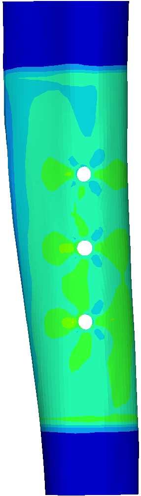
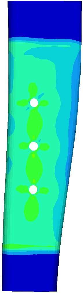
6 Figure 4. Torque versus angle plot of the experimental and FE models Contours of major principal stress, minor principal stress, and maximum shear stress are shown in Figures 5, 6, and 7 respectively. In these contours, the two time points are pictured to show the development of stress, and the areas that are dark red-orange or red have exceeded the stress limitations of the composite cortical bone. The drill holes deformed under the torsional loading, and locations of high stress concentrations developed around their edges. As shown in the contours, major principal stress (tension) concentrations occurred at an angle of 45 degrees around the holes, and shear stress concentrations occurred in the transverse and vertical directions. As anticipated, the minor principal stress (compression) was a mirror image of the major principal stress and was concentrated at an angle of negative 45 degrees around the holes. (a) medial lateral (b) medial lateral Figure 5. Major principal stress contours at (a) the fracture rotation angle determined by experiment and (b) the stress limits of the composite material. 6
")


7 (a) medial lateral (b) medial lateral Figure 6. Minor principal stress contours at (a) the fracture rotation angle determined by experiment and (b) the stress limits of the composite material. (a) medial (b) laterall medial lateral Figure 7. Maximum shear stress contours at (a) the fracture rotation angle determined by experiment and (b) the stress limits of the composite material. 7
8 Upper Edge (a) (b) Lower Edge Figure 8. Fracture path comparison of (a) experimental analogue tibia specimen and (b) FE model major principal stress contour. When loaded in torsion, long bones fail on a plane at 45 degrees to the loading axis [20, 21]. This is the plane of maximum tensilee stress; therefore, the major principal stress contour is the best indicator for potential fracture sites. Figure 8 compares this stress contour with an experimental specimen fracture, which initiated at a 45 degree angle through the lower hole on the medial surface. In the FE model, the major principal stress concentrations were highest at a 45 degree angle around this same hole. Furthermore, the principal stress was higher on the upper inside edge of this hole than on the lower edge. Discussion To our knowledge, this is the first study to evaluate the torsional strength of a composite analogue tibia with bicortical holes using both experimental and FE models. In this study, the tibia was selected because 1) tibial shaft fractures are common injuries that occur after falls, car accidents, sports injuries, and other activities, 2) plates and screws are commonly used for fracture fixation of the tibia, and 3) the tibia, in comparison to other long bones, is subjected to more pure torsional loads, rather than combination loading (bending, compression, tension). Furthermore, an analogue tibia was used to reduce variability between specimens and allow examination of essentially anatomically identical specimens. Cadaveric specimens, on the other hand, vary widely not only in their geometry but also in their bone density and tissue properties, which are affected by disease and aging. According to the available literature, the fourthaverage healthy generation analogue models fall within the published physiological range of adult bones (age: <80 years old) [22, 23, 24, 25, 26]. There are limitations to the models. Firstly, over time, bone in the clinical situation is known to remodel and fill screw holes after orthopedic hardware removal. The experimental and FE models can only validate the clinical situation in regards to fresh holes. Secondly, only cortical bone was simulated in the FE model, while the experimental model had two materials to represent the bone tissues: short fiber filled epoxy for cortical bone and rigid polyurethane foam for cancellous bone. Papini et al. [13] found that omitting the cancellous bone from a 8
9 computational model resulted in axial and torsional stiffness within 1% of those obtained when modeling both the cancellous and cortical bone due to the fact that the modulus of cancellous bone was more than an order of magnitude smaller than that of cortical bone. Since the elastic modulus of the two analogue bone materials were two orders of magnitude different, omission of the cancellous bone from the FE model did not significantly affect the results. Thirdly, the experimental model contained screw holes, while the FE model contained drill holes. Cortical screws were inserted and removed from the experimental specimens, and the impressions left by the screw threads create potential sites for fracture initiation [27]. In a FE model, small features such as screw threads reduce element size and increase analysis time. Therefore, screw threads were omitted, and holes with an average diameter of the cortical screws were modeled. Former research related to holes in bones subjected to torsion also simplified FE models by omitting screw threads [9, 11, 12]. There are also limitations within the FE material model which attributed to differences between the FE and experimental models. The specific torsional stiffness of the FE model is lower than the experimental model because the FE material model only uses one modulus and does not account for both the transverse and tensile moduli of the composite. Both shear and tension play a significant role in the simulation, and although the failure mode was in tension, the transverse modulus was used because of the torsional loading. With the transverse modulus being 37% lower than the tensile modulus, omission of the tensile modulus resulted in a low torsional stiffness, which did not mimic the torsional stiffness of the experimental model. Furthermore, the linear material model does not simulate yielding, which the experimental analogue tibia demonstrated with the gradual decline in stiffness with increased torsion. Without yielding the stress levels increased at an artificially high rate, which contributed to the FE model reaching the stress limitations at a relatively low torque in comparison to the experimental fracture torque. Considering future use of the FE model, material properties simulating human bone would be more useful than properties simulating analogue bone. Therefore, further development of the composite material model was not pursued, and the incorporation of a material model simulating human bone was reserved for a future study. Locations of stress concentrations are well predicted by the FE model and thus, potential fracture sites can be identified. During the experiment, the analogue tibia fractured along a helix at an angle of 45 degrees passing through the lower hole on the medial surface. The FE model predicted the same fracture site as the experimental model, and further determined that the fracture would initiate on the upper inside edge of this hole. In both the experimental and FE models, the locations of the stress concentrations around the holes were consistent with the findings of Kuo et al. [11], which show that fractures in tubes having a single-cortex hole of small defect ratios, 10-40%, propagate along a helix with an angle of 45 degrees. The defect ratio of the FE model (16%) was within this range, and high stress concentrations around the holes were at the predicted angle of 45 degrees. Conclusion A finite element computer model of an analogue tibia with bicortical holes simulated an experimental torsional fracture test and successfully predicted the location of initial fracture and the fracture torque within the standard deviation of experimental results. For further advancement of the model, material properties representing human bone can be incorporated, 9
10 and results can be compared to those obtained with human cadaveric specimens. Further studies could utilize this model to investigate variables such as bone quality, hole size, hole shape, spacing between holes, and direction of rotation. Additionally, this model could be compared to a cylindrical tube model to see how geometric simplification affects the torsional response. Acknowledgements The authors thank Altair applications engineer Mark Virginia for assisting this study with exceptional technical support. 10
11 List of Figures Figure 1. Experimental model. (a) Section of analogue tibia tested (b) Experimental setup... 3 Figure 2. FE model. (a) Section of the distal tibia modeled (b) Position of the transverse drill holes... 3 Figure 3. Nodes subjected to loading, rotation, and/or constraints Figure 4. Torque versus angle plot of the experimental and FE models... 6 Figure 5. Major principal stress contours at (a) the fracture rotation angle determined by experiment and (b) the stress limits of the composite material Figure 6. Minor principal stress contours at (a) the fracture rotation angle determined by experiment and (b) the stress limits of the composite material Figure 7. Maximum shear stress contours at (a) the fracture rotation angle determined by experiment and (b) the stress limits of the composite material Figure 8. Fracture path comparison of (a) experimental analogue tibia specimen and (b) FE model major principal stress contour List of Tables Table 1. Stress limits of the analogue cortical bone composite material [18]... 5 Table 2. Summary of Results... 5
12 References [1] Anderson LD, Sisk D, Tooms RE, and Park W 3rd "Compression-plate fixation in acute diaphyseal fractures of the radius and ulna." Journal of Bone and Joint Surgery American. 57(3): [2] Hidaka S, and Gustilo RB "Refracture of bones of the forearm after plate removal." Journal of Bone and Joint Surgery American. 66(8): [3] Mih AD, Cooney WP, Idler RS, and Lewallen DG "Long-term follow-up of forearm bone diaphyseal plating." Clinical Orthopaedics and Related Research. 299: [4] Tonino AJ, Davidson CL, Klopper PJ, and Linclau LA "Protection from stress in bone and its effects: experiments with stainless steel and plastic plates in dogs." Bone & Joint Surgery. 58(B): [5] Moyen BJ-L, Labey PJ Jr, Weinberg EH, and Harris WH "Effects on intact femora of dogs of the application and removal of metal plates." Bone & Joint Surgery. 60(A): [6] Rosson J, Egan J, and Shearer J Bone Weakness after the Removal of Plates and Screws. Cortical Atrophy or Screw Holes. Bone & Joint Surgery. 73(2): [7] Clark CR, Morgan C, Sonstegard DA, and Matthews LS The Effect of Biopsy- Hole Shape and Size on Bone Strength. Bone & Joint Surgery. 59(2): [8] Edgerton BC, Morrey BF, and An KN Torsional Strength Reduction due to Cortical Defects in Bone. Orthopaedic Research. 8(6): [9] Reminger a, Miclau T, and Lindsey R "The Torsional Strenght of Bones with Residual Screw Holes from Plates with Unicortical and Biocortical Purchase." Clinical Biomechanics. 12(1):71:73. [10] Hipp JA, Edgerton BC, An KN, and Hayes WC Structual Consequensces of Transcortical Holes in Long Bones Loaded in Torsion. Biomechanics. 23(12): [11] Kuo RF, Chao EYS, Rim K, and Park JB The Effect of Defect Size on the Stress Concentration and Fracture Characteristics for a Tubular Torsional Model with a Transverse Hole. Biomechanics. 24(2): [12] Cheung G, Zalzal P, Bhandari M, Spelt JK, and Papini M Finite Element Analysis of a Femoral Retrograde Intramedullary Nail Subject to Gait Loading. Medical Engineering & Physics. 26(2): [13] Papini M, Zdero R, Schemitsch EH, and Zalzal P The Biomechanics of Human Femurs in Axial and Torsional Loading: Comparison of Finite Element Analysis, Human Cadaveric Femurs, and Synthetic Femurs. Biomechanical Engineering. 129(1): [14] Completo A, Fonseca F, and Simoes JA Finite Element Experimental Cortex Strains of the Intact and Implanted Tibia. Biomechanical Engineering. 129(5):
13 [15] Keyak JH, and Rossi S Prediction of Femoral Fracture Load using Finite Element Models: An Examination of Stress- and Strain- Based Failure Theories. Biomechanics. 33(2): [16] Lotz JC, Cheal, EJ, and Hayes WC Fracture Prediction for the Proximal Femur Using Finite Element Models: Part I Linear Anaysis. Biomechanical Engineering. 113(4): [17] Beillas P, Lee SW, Tashman S, and Yang KH Sensitivity of Tibio-femoral Response to Finite Element Modeling Parameters. Computer Methods in Biomechanics and Biomedical Engineering. 10(3): [18] Pacific Research Laboratories, Inc., Vashon, Washongton. Composite Bones. (Retrieved 2012). [19] Gray HA, Zavatsky AB, Taddei F, Cristofolini L, and Gill HS Experimental Validation of a Finite Element Model of a Composite Tibia. Proceedings of the Institution of Mechanical Engineers. 221(3): [20] Brooks DB, Burstein AH, and Frankel VH "The biomechanics of torsional fractures: the stress concentration effect of a drill hole." Journal of Bone and Joint Surgery American. 52(A): [21] Peterson DL, Skraba JS, Moran JM, and Greenwald AS "Fracture of long bone: rate effects under singular and combined loading states." Journal of Orthopaedic Research. 1: [22] Cristofolini L, and Viceconti M "Mechanical Validation of Whole Bone Composite Tibia Models." J Biomech. 33(3): [23] Cristofolini L, Viceconti M, Cappello A, and Toni A "Mechanical Validation of Whole Bone Composite Femur Models." J Biomech. 29(4): [24] Heiner AD "Structural Properties of Fourth-Generation Composite Femurs and Tibias." J Biomech. 41(15): [25] Heiner AD, and Brown TD Structural Properties of a New Design of Composite Replicate Femurs and Tibias. Biomechanics. 34(6): [26] Gardner MP, Chong AC, Pollock AG, and Wooley PH Mechanical Evaluation of Large-Size Fourth-Generation Composite Femur and Tibia Models. Ann Biomed Eng. 38(3): [27] Malone CB, Heiple KG, and Burstein AH Bone Strength: Before and After Removal of Unthreaded and Threaded Pin and Screw. Clinical Orthopaedics & Related Research. 123:
Types of Plates 1. New Dynamic Compression Plate: Diaphyseal fracture: Radius, Ulna, Humerus, Rarely tibia
 Types of Plates 1. New Dynamic Compression Plate: DCP Diaphyseal fracture: Radius, Ulna, Humerus, Rarely tibia 1. Undercut adjacent to the holes low contact: less stress shield 2. Undercut at the undersurface
Nailing Stability during Tibia Fracture Early Healing Process: A Biomechanical Study
 Nailing Stability during Tibia Fracture Early Healing Process: A Biomechanical Study Natacha Rosa, Fernão D. Magalhães, Ricardo Simões and António Torres Marques Enhanced Bone Healing in intramedullary
Finite Element Analysis of Proximal Femur Nail for Subtrochanteric Fractured Femur
 Finite Element Analysis of Proximal Femur Nail for Subtrochanteric Fractured Femur Sowmianarayanan.S Assistant Consultant, Tata Consultancy Services Limited Prof. A.Chandrasekaran Professor, Dept. of Orthopaedic
AcUMEDr. Anatomic Midshaft Forearm Plates
 AcUMEDr Anatomic Midshaft Forearm Plates Anatomic Midshaft Forearm Plates Since 1988, Acumed has been designing solutions to the demanding situations facing orthopaedic surgeons, hospitals and their patients.
Plate and Bone Stresses for Single- and Double-Plated Femoral Fractures. D.R. Carter and R. Vasu
 Plate and Bone Stresses for Single- and Double-Plated Femoral Fractures D.R. Carter and R. Vasu J. Biomech 14: 55-62, 1981 Loading Koch Conditions Intact Trans-cortical stress Composite Beam Representation
The change in energy absorbed post removal of metalwork in a simulated paediatric long bone fracture
 J Child Orthop (2014) 8:443 447 DOI 10.1007/s11832-014-0606-z BASIC SCIENCE The change in energy absorbed post removal of metalwork in a simulated paediatric long bone fracture Alan J. Howieson Michael
Biomechanics of Fractures and Fixation
 Biomechanics of Fractures and Fixation Theodore Toan Le, MD Original Author: Gary E. Benedetti, MD; March 2004 New Author: Theodore Toan Le, MD; Revised October 09 Basic Biomechanics Material Properties
Plate Fixation Options
 Distal tibia extra-articular fractures can be difficult to treat Tenuous soft tissue Complex fracture patterns Plate Fixation Options Medial plating: Minimally invasive approach Technical ease Anterolateral
An effort is made to analyse the stresses experienced by the human femur. In order
 Finite Element Analysis of Human Femur Bone U N Mughal 1, H A Khawaja 2*, M Moatamedi 1, M Souli 3 1. Narvik University College, Norway 2. UiT-The Arctic University of Norway, Norway 3. University of Lille,
Effect of Screws Placement on Locking Compression Plate for Fixating Medial Transverse Fracture of Tibia
 Effect of Screws Placement on Locking Compression Plate for Fixating Medial Transverse Fracture of Tibia Ehsan Taheri *1, Behrooz Sepehri 2, Reza Ganji 3, Cyrus Nasirai 4 1 Mashhad Branch, Islamic Azad
LISS DF and LISS PLT. Less Invasive Stabilization Systems for Distal Femur and Proximal Lateral Tibia.
 LISS DF and LISS PLT. Less Invasive Stabilization Systems for Distal Femur and Proximal Lateral Tibia. LISS DF and LISS PLT. Less Invasive Stabilization Systems for Distal Femur and Proximal Lateral Tibia.
Fracture fixation. Types. Mechanical considerations. Biomechanics of fracture fixation. External fixation. Internal fixation
 Fracture fixation Biomechanics of fracture fixation Types External fixation Mechanical considerations Internal fixation Mechanical considerations in treatment of 1. In the external fixation: fracture When
Comparative Study of Fixation Devices for Intertrochanteric Fractures
 Comparative Study of Fixation Devices for Intertrochanteric Fractures C. Sticlaru * A. Davidescu Politehnica University of Timişoara Politehnica University of Timişoara Timişoara, România Timişoara, România
Technique Guide. DCP and LC-DCP Systems. Dynamic Compression Plates (DCP) and Dynamic Compression Plates with Limited Bone Contact (LC-DCP).
 and Dynamic Compression Plates with Limited Bone Contact (LC-DCP).") Technique Guide DCP and LC-DCP Systems. Dynamic Compression Plates (DCP) and Dynamic Compression Plates with Limited Bone Contact (LC-DCP). Table of Contents Introduction DCP and LC-DCP Systems 2 Indications
Technique Guide DCP and LC-DCP Systems. Dynamic Compression Plates (DCP) and Dynamic Compression Plates with Limited Bone Contact (LC-DCP). Table of Contents Introduction DCP and LC-DCP Systems 2 Indications
Relationship between the Apex of Flexible Nail and the Level of Fracture: A Biomechanical Study Ahmed N* 1, Gakhar H 2, Cheung G 3, Sharma A 4
 Relationship between the Apex of Flexible Nail and the Level of Fracture: A Biomechanical Study Ahmed N* 1, Gakhar H 2, Cheung G 3, Sharma A 4 Abstract Background Centre of Orthopaedic biomechanics, Bath
LOCKING TEP LOCKING TITANIUM ELASTIC PIN INTRAMEDULLARY NAIL
 LOCKING TEP LOCKING TITANIUM ELASTIC PIN INTRAMEDULLARY NAIL ... Index -3 3-8 8 9 9 0 7 Introduction Features Indicatiıons Surgical Technique Femoral Surgical Technique Tibial Surgical Technique Ulna Radius
Designing a Novel Fixation Device for Pediatric Orthopaedic Tibia Fractures
 Designing a Novel Fixation Device for Pediatric Orthopaedic Tibia Fractures Evan Lange, Karl Kabarowski Tyler Max, Sarah Dicker Client: Dr. Matthew Halanski, MD Advisor: Dr. Paul Thompson, PhD Biomedical
Topology optimisation of hip prosthesis to reduce stress shielding
 Computer Aided Optimum Design in Engineering IX 257 Topology optimisation of hip prosthesis to reduce stress shielding S. Shuib 1, M. I. Z. Ridzwan 1, A. Y. Hassan 1 & M. N. M. Ibrahim 2 1 School of Mechanical
Surgical Technique. Cannulated Angled Blade Plate 3.5 and 4.5, 90
 Surgical Technique Cannulated Angled Blade Plate 3.5 and 4.5, 90 Cannulated Angled Blade Plate 3.5 and 4.5, 90 Table of contents Indications/Contraindications 2 Implants 3 Surgical technique 5 Implant
LCP Distal Tibia Plate
 Surgical Technique LCP Locking Compression Plate Original Instruments and Implants of the Association for the Study of Internal Fixation AO/ASIF Table of contents Indications 3 Implants/Instruments 5 Surgical
Technique Guide. LCP Proximal Femoral Hook Plate 4.5/5.0. Part of the LCP Periarticular Plating System.
 Technique Guide LCP Proximal Femoral Hook Plate 4.5/5.0. Part of the LCP Periarticular Plating System. Table of Contents Introduction Features and Benefits 2 AO ASIF Principles 4 Indications 5 Surgical
11 5 New Cavendish Street, The Impact Properties of Bane. R.P. Oickenson, J.W. Wall and w.c. Hutton
 -249- The Impact Properties of Bane R.P. Oickenson, J.W. Wall and w.c. Hutton Medical Engineering Unit, Division of Engineering, Polytechnic of Central London, 11 5 New Cavendish Street, London WlM BJS
SMV Scientific Bone Plate and Screw System Surgical Technique
 SMV Scientific Bone Plate and Screw System Surgical Technique Description: The SMV Scientific Bone Plate and Screw System consists of non-locking plates and bone screw fasteners in a variety of lengths,
3.5 mm Locking Attachment Plate
 For Treatment of Periprosthetic Fractures 3.5 mm Locking Attachment Plate Surgical Technique Table of Contents Introduction 3.5 mm Locking Attachment Plate 2 Indications 4 Surgical Technique Preparation
Zimmer Small Fragment Universal Locking System. Surgical Technique
 Zimmer Small Fragment Universal Locking System Surgical Technique Zimmer Small Fragment Universal Locking System 1 Zimmer Small Fragment Universal Locking System Surgical Technique Table of Contents Introduction
The Vilex FUZETM. Dual Thread Screw & Intramedullary Nail in One Implant. The Ultimate TTC Arthrodesis Internal Fixator
 The Vilex FUZETM Dual Thread Screw & Intramedullary Nail in One Implant The Ultimate TTC Arthrodesis Internal Fixator Introduction The Vilex FUZE TM TTC Arthrodesis Compression Nail combines the attributes
S U R G I C A L T E C H N I Q U E David A. McQueen, MD Return to Menu
 S U R G I C A L T E C H N I Q U E David A. McQueen, MD TOTAL KNEE INSTRUMENTS Wichita Fusion Nail Introduction...1 Preoperative Planning...2 Surgical Technique...3-8 Wichita Fusion Nail Surgical Technique
We have assessed the influence of isolated and
 The effect of rotational malunion of the radius and the ulna on supination and pronation AN EXPERIMENTAL INVESTIGATION C. E. Dumont, R. Thalmann, J. C. Macy From the University of Zürich, Switzerland We
Mechanical Aspects of an Interference Screw Placement in ACL Reconstruction
 Mechanical Aspects of an Interference Screw Placement in ACL Reconstruction Mahmoud Chizari 1, Mohammad Alrashidi 2, Khaled Alrashdan 2, Ibrahim Yildiz 3, Jamaluddin Mahmud 4 1 School of Engineering and
Locked Plating: Biomechanics and Biology
 Techniques in Orthopaedics 22(4):E1 E6 2007 Lippincott Williams & Wilkins, Inc. Locked Plating: Biomechanics and Biology Kyle F. Dickson, M.D., M.B.A., John W. Munz, M.D. Summary: Since the early ideas
AcUMEDr. FoREARM ROD SYSTEM
 AcUMEDr FoREARM ROD SYSTEM FoREARM ROD SYSTEM Since 1988 Acumed has been designing solutions to the demanding situations facing orthopedic surgeons, hospitals and their patients. Our strategy has been
Surgical Technique. Anterolateral and Medial Distal Tibia Locking Plates
 Surgical Technique Anterolateral and Medial Distal Tibia Locking Plates PERI-LOC Periarticular Locked Plating System Anterolateral and Medial Distal Tibia Locking Plates Surgical Technique Contents Product
ANATOMIC LOCKED PLATING SYSTEM
 ANATOMIC LOCKED PLATING SYSTEM There is only one...dvr Anatomic. There is only one... ANATOMIC LOCKED PLATING SYSTEM Distal Tibia TiMAX for strength, biocompatibility and enhanced imaging capabilities
Technique Guide. 3.5 mm LCP Low Bend Medial Distal Tibia Plate Aiming Instruments. Part of the 3.5 mm LCP Percutaneous Instrument System.
 Technique Guide 3.5 mm LCP Low Bend Medial Distal Tibia Plate Aiming Instruments. Part of the 3.5 mm LCP Percutaneous Instrument System. Table of Contents Introduction 3.5 mm LCP Low Bend Medial Distal
Biomechanical Analysis of Hip Joint Arthroplasties using CT-Image Based Finite Element Method
 Research Article Biomechanical Analysis of Hip Joint Arthroplasties using CT-Image Based Finite Element Method Mitsugu Todo * Research Institute for Applied Mechanics, Kyushu University, Kasuga, Japan
Cannulated Angled Blade Plate 3.5 and 4.5, 90.
 Cannulated Angled Blade Plate 3.5 and 4.5, 90. Technique Guide This publication is not intended for distribution in the USA. Instruments and implants approved by the AO Foundation. Table of Contents Introduction
Transactions on Biomedicine and Health vol 3, 1996 WIT Press, ISSN
 Evaluation of forearm fixation plate design using finite element methods S.H. Saidpour, I.M. Flitta, X. Velay School ofdesign Engineering and Computing, Department of Product Design and Manufacture, Bournemouth
Finite Element Analysis of Radius and Ulna. Eli Pavlatos April 24, 2013
 Finite Element Analysis of Radius and Ulna Eli Pavlatos April 24, 2013 Outline Review bone biomechanics bone behavior during fracture Stress analysis concepts properties of bone for models Fracture simulations
Surgical Technique. Lower Extremity Plates and Straight Plates
 Surgical Technique Lower Extremity Plates and Straight Plates 2 Table of contents Overview...4 Indications... 4 Contraindications... 4 Screw Options... 5 Straight Plate Options... 6 Proximal Tibia Plate
Locked plating constructs are creating a challenge for surgeons.
 Locked plating constructs are creating a challenge for surgeons. Three recent studies examining supracondylar femur fractures show concern for the high degree of stiffness of locked plating constructs
Patel V, Venkatarayappa I, Prayson MJ, Goswami T. Biomechanical evaluation of hybrid locking plate constructs. Hard Tissue 2013 Jun 01;2(4):32.
:32.") Patel V, Venkatarayappa I, Prayson MJ, Goswami T. Biomechanical evaluation of hybrid locking plate constructs. Hard Tissue 2013 Jun 01;2(4):32. Licensee OA Publishing London 2013. Creative Commons Attribution
Patel V, Venkatarayappa I, Prayson MJ, Goswami T. Biomechanical evaluation of hybrid locking plate constructs. Hard Tissue 2013 Jun 01;2(4):32. Licensee OA Publishing London 2013. Creative Commons Attribution
Technique Guide. 3.5 mm LCP Proximal Tibia Plate. Part of the Synthes Small Fragment LCP System.
 Technique Guide 3.5 mm LCP Proximal Tibia Plate. Part of the Synthes Small Fragment LCP System. Table of Contents AO ASIF Principles of Internal Fixation 4 Indications/Contraindications 5 Surgical Technique
BIOMECHANICAL INVESTIGATION OF A NEW HYBRID COMPOSITE MATERIAL FOR USE IN INTRAMEDULLARY NAILING IN FEMORAL SHAFT FRACTURES
 BIOMCHANICAL INVSTIGATION OF A NW HYBRID COMPOSIT MATRIAL FOR US IN INTRAMDULLARY NAILING IN FMORAL SHAFT FRACTURS S. Samiezadeh a, P. Tavakkoli Avval a, Z. Fawaz b, H. Bougherara a* a Department of Mechanical
Mehmet Erdil 1,Hasan Huseyin Ceylan 2, Deniz Kara 3,Gokhan Polat 4, Ergun Bozdag 5, Emin Sunbuloglu 5
 Mehmet Erdil 1,Hasan Huseyin Ceylan 2, Deniz Kara 3,Gokhan Polat 4, Ergun Bozdag 5, Emin Sunbuloglu 5 1. Istanbul Medipol University, Orthopaedics & Traumatology Dep.,Istanbul,TURKEY 2. Sultanciftligi
International Journal of Engineering Research and Development e A Mathematical Model to Calculate Contact Stresses In Artificial Human Hip Joint
 International Journal of Engineering Research and Development e-issn: 2278-067X, p-issn: 2278-800X, www.ijerd.com Volume 6, Issue 12 (May 2013), PP. 119-123 A Mathematical Model to Calculate Contact Stresses
LCP Low Bend Medial Distal Tibia Plates 3.5 mm. Anatomic plates with low profile head for intra- and extraarticular fractures.
 LCP Low Bend Medial Distal Tibia Plates 3.5 mm. Anatomic plates with low profile head for intra- and extraarticular fractures. Surgical Technique This publication is not intended for distribution in the
A biomechanical study of the Birmingham mid head resection arthroplasty Aghayan, Sam; Shepherd, Duncan; Davis, Edward
 A biomechanical study of the Birmingham mid head resection arthroplasty Aghayan, Sam; Shepherd, Duncan; Davis, Edward DOI: 10.1177/0954411913485057 License: None: All rights reserved Document Version Peer
LCP Medial Distal Tibia Plate, without Tab. The Low Profile Anatomic Fixation System with Angular Stability and Optimal Screw Orientation.
 LCP Medial Distal Tibia Plate, without Tab. The Low Profile Anatomic Fixation System with Angular Stability and Optimal Screw Orientation. Technique Guide LCP Small Fragment System Table of Contents Introduction
Effect of the femoral stem size on femur bone quality towards THR
 Original article: Effect of the femoral stem size on femur bone quality towards THR Palash Kumar Maji a,*, Amit Roy Chowdhury b, Debasis Datta b, S Karmakar a, Subhomoy Chatterjee b and A K Prasad a a
CRANIO AND MAXILLOFACIAL
 CRANIO AND MAXILLOFACIAL SURGICAL CATALOG 2016 A Division of Pacific Research Laboratories, Inc. WWW.SAWBONES.COM Our name Sawbones is synonymous with the generic name of hands on workshop bones used for
[ICESTM-2018] ISSN Impact Factor
![[ICESTM-2018] ISSN Impact Factor](/thumbs/88/117546298.jpg "[ICESTM-2018] ISSN Impact Factor") GLOBAL JOURNAL OF ENGINEERING SCIENCE AND RESEARCHES MODELING AND FINITE ELEMENT ANALYSIS OF KNEE JOINT PROSTHESIS U.D.S.Prathap varma *1,S.Rajesh 2, B.Suresh Kumar 3 & P.Rama Murthy Raju 4 *1 M.TechScholar,
GLOBAL JOURNAL OF ENGINEERING SCIENCE AND RESEARCHES MODELING AND FINITE ELEMENT ANALYSIS OF KNEE JOINT PROSTHESIS U.D.S.Prathap varma *1,S.Rajesh 2, B.Suresh Kumar 3 & P.Rama Murthy Raju 4 *1 M.TechScholar,
EVOS MINI with IM Nailing
 Case Series Dr. John A. Scolaro EVOS MINI with IM Nailing A series of studies Introduction Intramedullary nailing has become the standard for many long bone fractures. Fracture reduction prior to nail
Technique Guide. TomoFix Osteotomy System. A comprehensive plating system for stable fixation of osteotomies around the knee.
 Technique Guide TomoFix Osteotomy System. A comprehensive plating system for stable fixation of osteotomies around the knee. Table of Contents Introduction TomoFix Osteotomy System 2 AO Principles 4 Indications
RibFix Blu. Thoracic Fixation System
 RibFix Blu RibFix Blu Thoracic Fixation System The New Era of Rib Fixation Begins Now Designed by Trauma Surgeons for Trauma Surgeons Your work matters and so do your patients. We are continually engineering
External Skeletal Fixation (ESF)
") External Skeletal Fixation (ESF) Technique for fracture repair in animals Introduction External Skeletal Fixation is a versatile and effective technique for fracture repair in animals, rigidly stabilizing
External Skeletal Fixation (ESF) Technique for fracture repair in animals Introduction External Skeletal Fixation is a versatile and effective technique for fracture repair in animals, rigidly stabilizing
3.5 mm LCP Low Bend Medial Distal Tibia Plate Aiming Instruments
 Part of the 3.5 mm LCP 3.5 mm LCP Low Bend Medial Distal Tibia Plate Aiming Instruments Surgical Technique TABLE OF CONTENTS INTRODUCTION 3.5 mm LCP Low Bend Medial Distal Tibia Plate 2 Aiming Instruments
MODELING AND ANALYSIS OF SOME STABILIZATION SYSTEMS OF RADIUS FRACTURES
 MODELING AND ANALYSIS OF SOME STABILIZATION SYSTEMS OF RADIUS FRACTURES Prof.dr.eng. Mirela TOTH-TAŞCĂU, Lecturer.dr.eng. Lucian RUSU, PhD.eng. Flavia BĂLĂNEAN, PhD.eng. Cristian TOADER-PASTI, Politehnica
Failure criteria for Adhesives. Sainath Kadam, 3mE 19 oktober 2014
 Failure criteria for Adhesives Sainath Kadam, 3mE 19 oktober 2014 () Failure criteria for Adhesives 1 / 59 Outline 1 Introduction 2 Testing 3 Data analysis 4 FEM 5 Results and Conclusions () Failure criteria
NEW INSTRUMENTS FOR INTERNAL FIXATION OF FRACTURES USING MINIMALLY INVASIVE TECHNIQUES
 NEW INSTRUMENTS FOR INTERNAL FIXATION OF FRACTURES USING MINIMALLY INVASIVE TECHNIQUES Dr.eng. Comşa Stanca, sing. Gheorghiu Doina, eng. Ciobota Dan National Institute of Research & Development for fine
Fractures of the tibia shaft treated with locked intramedullary nail Retrospective clinical and radiographic assesment
 ARS Medica Tomitana - 2013; 4(75): 197-201 DOI: 10.2478/arsm-2013-0035 Șerban Al., Botnaru V., Turcu R., Obadă B., Anderlik St. Fractures of the tibia shaft treated with locked intramedullary nail Retrospective
Analysis of Plate Bone Construct Failure Following Tibial Tuberosity Advancment
 Analysis of Plate Bone Construct Failure Following Tibial Tuberosity Advancment W. T. McCartney 1,2 E. Galvin 2 B Mac Donald D Comiskey 3 1 Marie Louise Veterinary Hospital, Baldoyle, Dublin 13, Ireland
Stress Distribution in Human Tibia Bones using Finite Element Analysis
 Article Stress Distribution in Human Tibia Bones using Finite Element Analysis Wanchalerm Tarapoom a and Tumrong Puttapitukporn b,* Department of Mechanical Engineering, Faculty of Engineering, Kasetsart
White Paper for Rotational Stability. *smith&nephew SL-PLUS MIA. Cementless Hip Stem System
 White Paper for Rotational Stability *smith&nephew SL-PLUS MIA Cementless Hip Stem System SL-PLUS MIA Building on the long-term success of the SL-PLUS hip stem, the SL-PLUS MIA hip stem has been developed
Improving Fixation of a Previously Designed Pediatric Tibial Stent
 Improving Fixation of a Previously Designed Pediatric Tibial Stent Evan Lange, Karl Kabarowski, Tyler Max, Sarah Dicker, Lida Acuña-Huete Client: Dr. Matthew Halanski, MD Advisor: Dr. Wan-Ju Li, PhD Biomedical
Keywords: Angioplasty, Explicit finite elements method, Tube hidroforming, Stents.
 Blucher Mechanical Engineering Proceedings May 2014, vol. 1, num. 1 www.proceedings.blucher.com.br/evento/10wccm AN ANALYSIS OF THE CONTACT BETWEEN THE STENT AND THE ARTERY USING TUBE HIDROFORMING SIMULATION
Technique Guide. Locking Attachment Plate. For treatment of periprosthetic fractures.
 Technique Guide Locking Attachment Plate. For treatment of periprosthetic fractures. Table of Contents Introduction Locking Attachment Plate 2 Indications 4 Surgical Technique Patient Positioning 5 Preparation
This is a repository copy of Mechanics of musculoskeletal repair devices.
 This is a repository copy of Mechanics of musculoskeletal repair devices. White Rose Research Online URL for this paper: http://eprints.whiterose.ac.uk/101054/ Version: Accepted Version Article: Harwood,
Surgical Technique. 3.5mm and 4.5mm Lateral Proximal Tibia Locking Plates
 Surgical Technique 3.5mm and 4.5mm Lateral Proximal Tibia Locking Plates PERI-LOC Periarticular Locked Plating System 3.5mm and 4.5mm Lateral Proximal Tibia Locking Plate Surgical Technique Contents Product
Conventus CAGE PH Surgical Techniques
 Conventus CAGE PH Surgical Techniques Conventus Orthopaedics The Conventus CAGE PH (PH Cage) is a permanent implant comprised of an expandable scaffold, made from nitinol and titanium, which is deployed
Wichita Fusion Nail Surgical Technique. David A. McQueen, MD
 Wichita Fusion Nail Surgical Technique David A. McQueen, MD The patented design with a dual advantage Generates compression intraoperatively Innovative compression screw (a) locks femoral and tibial components
Biomechanics of Two Reconstruction Techniques for Elbow Ulnar Collateral Ligament Insufficiency
 Biomechanics of Two Reconstruction Techniques for Elbow Ulnar Collateral Ligament Insufficiency Justin E. Chronister, MD 1, Randal P. Morris, BS 2, Clark R. Andersen, MS 2, J. Michael Bennett, MD 3, Thomas
LCP Anterior Ankle Arthrodesis Plates. Part of the Synthes Locking Compression Plate (LCP) System.
 System.") LCP Anterior Ankle Arthrodesis Plates. Part of the Synthes Locking Compression Plate (LCP) System. Technique Guide Instruments and implants approved by the AO Foundation Table of Contents Introduction
LCP Anterior Ankle Arthrodesis Plates. Part of the Synthes Locking Compression Plate (LCP) System. Technique Guide Instruments and implants approved by the AO Foundation Table of Contents Introduction
In-Silico approach on Offset placement of implant-supported bridges placed in bone of different density in Orthodontics.
 In-Silico approach on Offset placement of implant-supported bridges placed in bone of different density in Orthodontics. Chandrasenan.P 1, Vishnu.G 2, Akshay K Nair 3 1M Tech student, Department of Mechanical
Reduction of Pullout Strength Caused by Reinsertion of 3.5-mm Cortical Screws
 ORIGINAL ARTICLE Reduction of Pullout Strength Caused by Reinsertion of 3.5-mm Cortical Screws Amir Matityahu, MD,* Christof Hurschler, PhD, Markus Badenhop, Christina Stukenborg-Colsman, MD, Hazibullah
Technique Guide. 3.5 mm LCP Low Bend Medial Distal Tibia Plates. Part of the Synthes locking compression plate (LCP) system.
 system.") Technique Guide 3.5 mm LCP Low Bend Medial Distal Tibia Plates. Part of the Synthes locking compression plate (LCP) system. Table of Contents Introduction 3.5 mm LCP Low Bend Medial Distal Tibia Plates
Technique Guide 3.5 mm LCP Low Bend Medial Distal Tibia Plates. Part of the Synthes locking compression plate (LCP) system. Table of Contents Introduction 3.5 mm LCP Low Bend Medial Distal Tibia Plates
TIPMED EXTERNAL FIXATION SYSTEMS
 TIPMED EXTERNAL FIXATION SYSTEMS ANATOMICAL LOCATIONS FOR EXTERNAL FIXATION SYSTEMS Humeral Dynamic Axial Fixator Elbow Fixator Pelvic Dynamic Axial Fixator Pennig Wrist Fixator Hand Fixator Finger Fixator
Advanced FE Modeling of Absorbable PLLA Screws
 Advanced FE Modeling of Absorbable PLLA Screws Jorgen Bergstrom, Ph.D., David Quinn, Ph.D., Eric Schmitt jbergstrom@veryst.com, LLC September 14, 2011 Introduction Anterior cruciate ligament (ACL) reconstruction
Surgical Technique. Targeter Systems Overview
 Surgical Technique Targeter Systems Overview PERI-LOC Locked Plating System Targeter Systems Overview Table of contents Product overview... 2 Introduction... 2 Indications... 2 Design features and benefits...
Effect of implant stiffness on spinal growth in the pig spine
 Paediatric & Geriatric Orthopaedics Effect of implant stiffness on spinal growth in the pig spine R Rizza 1 *, XC Liu 2 *, J Thometz 2, C Tassone 2 Page 1 of 5 Abstract Introduction According to the vicious
Femur Condylar Plate System Procedural Steps.
 Femur Condylar Plate System Procedural Steps www.carbo-fix.com 1 Table of Contents Introduction..3 Instrumentation Set... 8 Procedural Steps:...... 12 Ordering Information 19 2 Introduction The CarboFix
Locking Radial Head Plates
 Locking Radial Head Plates Locking Radial Head Plates Since 1988, Acumed has been designing solutions to the demanding situations facing orthopaedic surgeons, hospitals and their patients. Our strategy
ISSN: ISO 9001:2008 Certified International Journal of Engineering and Innovative Technology (IJEIT) Volume 2, Issue 12, June 2013
 Volume 2, Issue 12, June 2013") Numerical Analysis of Human Femoral Bone in Different Phases Sherekar R.M, Pawar A.N. Department of Mechanical Engineering, Jawaharlal Darda Institute of Engineering and Technology, Yavatmal, 445001 (M.S).
Numerical Analysis of Human Femoral Bone in Different Phases Sherekar R.M, Pawar A.N. Department of Mechanical Engineering, Jawaharlal Darda Institute of Engineering and Technology, Yavatmal, 445001 (M.S).
Biomechanical and Clinical Evaluation of a New Operative Technique
 27 Posterior Olecranon Plating Biomechanical and Clinical Evaluation of a New Operative Technique Nirmal C. Tejwani, M.D., Ian R. Garnham, F.R.C.S., Philip R. Wolinsky, M.D., Frederick J. Kummer, Ph.D.,
The Mechanical Properties Of Fixing Greater Trochanter Or Lesser Trochanter In Complex Four Part Intertrochanteric Fractures
 The Mechanical Properties Of Fixing Greater Trochanter Or Lesser Trochanter In Complex Four Part Intertrochanteric Fractures Chih-Hui Chen 1, Kui-Chou Huang 2, Cheng-Kung Cheng, PhD 3, Hung-Chan Kao 4.
GAMMA LOCKING NAIL INSTRUMENTS OPERATIVE TECHNIQUE
 GAMMA LOCKING NAIL INSTRUMENTS OPERATIVE TECHNIQUE FEATURES AND BENEFITS The One Shot Device is a new component of the Gamma Locking Nail instrumentation system determining the correct position of the
Improvements and Validation of an Existing LS- DYNA Model of the Knee-Thigh-Hip of a 50 th Percentile Male Including Muscles and Ligaments
 Improvements and Validation of an Existing LS- DYNA Model of the Knee-Thigh-Hip of a 50 th Percentile Male Including Muscles and Ligaments Dr. Chiara Silvestri, Mario Mongiardini, Prof. Dr. Malcolm H.
The role of the calcar femorale in stress distribution in the proximal femuros4_
 Orthopaedic Surgery (2009), Volume 1, No. 4, 311 316 ORIGINAL ARTICLE The role of the calcar femorale in stress distribution in the proximal femuros4_53 311..316 Qi Zhang MD 1, Wei Chen MD 1, Huai-jun
Finite Element Analysis for the Treatment of Proximal Femoral Fracture
 Copyright 2009 Tech Science Press CMC, vol.11, no.1, pp.1-13, 2009 Finite Element Analysis for the Treatment of Proximal Femoral Fracture Ching-Chi Hsu 1, Jinn Lin 2, Yongyut Amaritsakul 3, Takalamesar
Simulation of bone indentation
 Modelling in Medicine and Biology VII 113 Simulation of bone indentation S. Kasiri 1, G. Reilly 1,2 & D. Taylor 1 1 Trinity Centre for Bioengineering, Trinity College Dublin, Ireland 2 Institute of Technology
Clinical. Solutions. Synthes Solutions. Foot and Ankle.
 Clinical Solutions Foot and Ankle. Foot and Ankle. Fractures of the tibial shaft Fractures of the distal fibula Fractures of the distal tibia Fractures and osteotomies of the calcaneus Arthrodesis Fractures,
LCP DISTAL TIBIA PLATE
 LCP DISTAL TIBIA PLATE Instruments and implants approved by the AO Foundation. This publication is not intended for distribution in the USA. SURGICAL TECHNIQUE Image intensifier control This description
Distal Radius Plate Instrument and Implant Set. Discontinued December 2017 DSUS/TRM/0916/1063(1)
") Distal Radius Plate Instrument and Implant Set Surgical Technique Discontinued December 2017 DSUS/TRM/0916/1063(1) The Distal Radius Plates Indications For fixation of fractures and osteotomies, including
Distal Radius Plate Instrument and Implant Set Surgical Technique Discontinued December 2017 DSUS/TRM/0916/1063(1) The Distal Radius Plates Indications For fixation of fractures and osteotomies, including
Low Bend Distal Tibia Plates
 Part of the DePuy Synthes Locking Compression Plate (LCP ) System 3.5 mm LCP Low Bend Medial Distal Tibia Plates Surgical Technique Table of Contents Introduction 3.5 mm LCP Low Bend Medial Distal Tibia
Correlation of Femoral Component Micromotion to a Physical Test Using an FEA Model.
 Correlation of Femoral Component Micromotion to a Physical Test Using an FEA Model. Robert Davignon, Ananthkrishnan Gopalakrishnan. Stryker Corporation, Parsippany, NJ, USA. Disclosures: R. Davignon: 3A;
INTRAMEDULLARY NAILING TIBIA AND FEMUR 1.3 TIBIAL AND FEMORAL NAILING FEMORAL NAILING WITH RETROGRADE INSERTION IMPLANTS AND OPERATING MANUAL
 1.3 TIBIA AND FEMORA NAIING FEMORA NAIING WITH RETROGRADE INSERTION IMPANTS AND OPERATING MANUA INTRAMEDUARY NAIING TIBIA AND FEMUR Medical Products Manufacturing and Trading td. General informations
AcUMEDr. Olecranon Threaded Compression Rod
 AcUMEDr Olecranon Threaded Compression Rod Olecranon Threaded Compression Rod Since 1988, Acumed has been designing solutions to the demanding situations facing orthopaedic surgeons, hospitals and their
AxSOS Locking Plate System
 AxSOS Locking Plate System Operative Technique Small Fragment Basic Fragment 1 2 Contents Page 1. Introduction 4 2. Features & Benefits 5 4 and 5mm Compression Plates 5 Reconstruction and 1/3 Tubular Locking
Influence of plate length on the Mechanical performance of dynamic hip screw
 2012 International Conference on System Modeling and Optimization (ICSMO 2012) IPCSIT vol. 23 (2012) (2012) IACSIT Press, Singapore Influence of plate length on the Mechanical performance of dynamic hip
An Analysis of Femoral Geometry Related to Deflection of the SIGN Nail When Inserted into a Femoral Model
 An Analysis of Femoral Geometry Related to Deflection of the SIGN Nail When Inserted into a Femoral Model Abstract Joseph Pia Background: Femur fractures treated with the SIGN nail can require additional
Effect of different load conditions on a DHS implanted human femur
 Effect of different load conditions on a DHS implanted human femur Nooshin S. Taheri, Aaron S. Blicblau, and Manmohan Singh Abstract As a result of improving life expectancy, the number of elderly people