PROMOS REVERSE Modular Shoulder System
|
|
|
- Homer Patterson
- 6 years ago
- Views:
Transcription

1 Surgical Technique
2
3 PROMOS REVERSE Modular Shoulder System Table of Contents Introduction... 2 Indications/Contraindications... 3 Preoperative Planning... 4 Patient Positioning... 5 Surgical Technique... 6 Revision Surgery Sterilization Implants Instrumentation Nota Bene The technique description herein is made available to the healthcare professional to illustrate the author s suggested treatment for the uncomplicated procedure. In the final analysis, the preferred treatment is that which addresses the needs of the specific patient. 1
4 Introduction The anatomical PROMOS modular shoulder prosthesis has been successfully applied as a standard cementless implant since 2003 and is indicated for primary and secondary omarthrosis and fractures. The modular PROMOS STANDARD prosthesis range can be expanded with the PROMOS REVERSE prosthesis component to extend the indications of the PROMOS system. The use of this modular extension is planned for arthrosis with advanced irreparable rotator cuff rupture, where conventional shoulder prosthesis would no longer provide sufcient pain-free joint stability or an adequate range of motion. The PROMOS REVERSE implant reverses the normal relationship of the scapular and humeral components of the glenohumeral joint. This allows stabilization and leads to the desired medialization and distalization of the rotational center. The reversal of the joint allows the three parts of the deltoid muscles to compensate for the insufficiency of the rotator cuff, to bring the articulation surfaces together and to stabilize the joint. This allows what is tantamount to normal joint function to be restored. The PROMOS Shoulder System uses the same distal shaft components for the standard prosthesis as for the reverse prosthesis. The proximal components for both systems can be added or removed in a modular system. The reverse prosthesis can therefore be used for primary treatment as well as for revisions following inadequate healing or resorption of the tubercle or can be used following secondary rotator cuff rupture. A standard body with a humeral head component can also be used if the glenoid components loosen or following a glenoid fracture as a last resort, while still maintaining the prosthesis shaft. The distal rectangular shaft is the ideal basis for a rotationally stable diaphyseal anchorage in the humerus. The distal anchorage allows major parts of the metaphyseal bone substance to be maintained in primary surgery, while still allowing a stable diaphyseal anchorage without bone transplantation in revision surgery with bone defects. 2

5 Indications/Contraindications Indications The PROMOS REVERSE Shoulder is indicated for use in a grossly deficient rotator cuff joint with severe arthropathy or a previous failed joint replacement with a grossly deficient rotator cuff joint The patient s joint must be anatomically and structurally suited to receive the selected implants and a functional deltoid muscle is necessary to use the device The glenoid baseplate is intended for cementless application with the addition of screws for fixation The humeral stem and body components are intended for cementless use Contraindications Complete palsy of the brachial plexus or axillary nerve Primary osteoarthritis or osteonecrosis when the articular surface-tuberosity relationships are normal and the rotator cuff is intact and functional. In this case a PROMOS STANDARD Shoulder is indicated Acute or chronic infections, local or systemic Infected operation site Severe muscular, neurological or vascular diseases that have the potential to endanger the extremity in question Too little bone substance or excessively poor bone quality, endangering the stable seating of the prosthesis Any concomitant diseases that endanger the function of the implant, such as: Allergy to the implant materials Severe renal insufficiency Severe cardiac insufficiency (e.g. due to increased metal-ion concentrations in the blood) Pregnancy Neuropathic shoulder (Charcot shoulder) 3

6 Preoperative Planning Preoperative planning should be carried out with the existing X-Ray templates to evaluate possible implant size and position of the implant. X-Ray pictures should be taken in true A/P and axillary views. Literature numbers for preoperative templates 1710: PROMOS REVERSE Humeral Components 1711: PROMOS REVERSE Glenoid Components Implant templates are available at 110% magnification. The resection level on the humeral template at the upper edge of the reverse body is placed over the X-Ray image. The resection line will be placed slightly (1 2mm) lower than the footprint of the greater tuberosity at a 155 angle to the shaft axis preferably by using the medium reverse body height template of 10mm. The stem size is now determined to fit the medullary canal by moving the register with the body in place. The size of the reverse body (36mm or 42mm) should be selected as large as possible to the anatomy. For additional information, the rotation centers of the different PE inserts are shown on the template. There are also templates for the glenoid components for both glenosphere diameters showing the centric and the eccentric version with the base plate and available screw lengths, to estimate adequate positioning of the base plate. The definitive sizes of the reverse body, PE insert and centric or eccentric glenosphere are generally decided during the operation using trial components. For a better imagination of the shape of the glenoid, a CT scan is recommended to get a better understanding for setting the glenoid screws. 4


7 Patient Positioning The patient is placed in a semi-sitting (beach chair) position, inclined approximately 30 or more. The patient should be positioned on the operating table as far as possible to the side being operated on. The shoulder and arm should come to rest beyond the edge of the table in order that the arm can be freely extended, adducted slightly, and subjected to external rotation. Especially in the case of obese patients, it is important to ensure good positioning with appropriate freedom of arm movement. Adequate exposure of the dislocated proximal humerus without torsional or flexural forces being exerted on the humerus by the edge of the table is essential for neat, safe implantation of shoulder prosthesis. The sterile drape is placed so that the arm can be moved freely during the operation. Optionally, an arm holder can be used. 5
.")
 allow precise orientation in relation to the humeral head.")
8 Surgical Technique Approach to the glenohumeral joint A standardized deltopectoral approach is recommended. An anterolateral McKenzie technique can be used as an alternative. Both approaches call for anatomically accurate and stable reinsertion of the muscle-tendon units (subscapularis tendon and/or the deltoid muscle). The deltopectoral interval is opened medial to the cephalic vein to preserve venous discharge from the deltoid muscle. The anterior humeral circumflex vessels are exposed and ligated. The anatomical landmarks (rotator interval, bicipital groove, lesser and greater tuberosities) allow precise orientation in relation to the humeral head. The subscapularis tendon is transected 1cm medial of the insertion on the lesser tuberosity together with the articular capsule and subsequently reinserted laterally, with a direct side-to-side, preferably transosseous suture of the tendon ends. Alternatively, the subscapularis tendon can also be detached from the lesser tuberosity with an osteotome and reattached with transosseous sutures, wires, or with a screw. Lengthening of the subscapularis is not needed if a complete release is performed. This step is crucial for adequate postoperative range of motion. We recommend circumferential mobilization of the subscapularis tendon. This is achieved by incision of the rotator interval including transection of the coracohumeral ligament at the base of the coracoid. Then the capsule is sharply released from the anterior glenoid and adhesions are resected, including the more medial tendon muscle unit from the anterior scapular neck. By means of this circumferential release, the tendon-muscle unit of the subscapularis muscle becomes functional again with normal excursion. This step is crucial for adequate postoperative range of motion. A continuation of the capsulotomy with release of the capsular contractures, especially inferiorly, facilitates the subsequently necessary dislocation of the humeral head in order to expose the humerus for humeral head preparation and anatomical resection. Attention to the n. axillaris has to be payed by palpation or visualization the nerve will be protected. After humeral head resection, a capsulotomy is completed in a later step, the aim being circumferential arthrolysis. 6


9 Resection of the humeral head Exposure of the humeral head is performed with cautious external rotation while the arm is held in the adducted and extended position. First, this maneuver is only possible if the patient is positioned correctly. The exposure is facilitated by the described release of capsular contractures by means of an extensive semicircumferential capsulotomy. As a result, complete external rotation is made possible with corresponding humeral head exposure without any flexural or torsional forces acting on the humeral stem. The patient s hand should point towards the head of the OR table. Cut off the tip of the humeral head approximately at the height of the recess to the anatomical neck with an oscillating saw to make an easier entry. Fit the handle with the quick adapter onto the awl. Fit the sleeve of the cutting device onto the awl. Insert the awl turning left and right into the center of the medullary canal. Press the pegs of the sleeve into the bone. Remove the handle from the awl. 7

 with the fixation screw M/L slightly loose, so that the block can be moved for the medial/lateral correct position.")
10 To perform an accurate cut, assemble the cutting device before placing it over the awl. The device is adjustable in: height anterior/posterior position medial/lateral position retrotorsion Choose the reverse cutting adapter left or right, according to the required side you need to operate. Screw the fixation screw M/L (blue) through the center of the oblong hole. Hold the humeral cutting block (yellow) with the fixation screw M/L slightly loose, so that the block can be moved for the medial/lateral correct position. Reverse Cutting Adapter Fixation Screw A/P Fixation Screw M/L Humeral Cutting Block Place the cutting adapter on the arm of the cutting device. Reverse Cutting Device Height Adjustment Screw Pretighten the cutting device with the fixation screw A/P (orange) of the adapter within the slotted area. Screw in the orientation pin with 0 to the arm on the cutting device or with 10 to the cutting adapter for the desired retrotorsion. Orientation pin 0 10 If the height adjustment screw (green) was disassembled for sterilization, preset the screw in the middle of the threaded cylinder. 8
 lower than the footprint of the greater tuberosity.")
.")
11 Place the cutting device on the awl with the sleeve. Adjust the device with the orientation pin corresponding to the axis of the forearm. The ideal retrotorsion of the resection is approximately 10. The pin set to 10 must be in line with the lower arm in 90 flexion. The resection shall be performed slightly (1 2mm) lower than the footprint of the greater tuberosity. The resection is made at a fixed 155 angle and therefore less steep than the anatomical cut of a PROMOS STANDARD which is usually between 130 and 140. Place the cutting adapter to determine the resection line. Adjust the adapter and the cutting block and secure them in the position with the fixation screws (orange, blue). Adjust the height by turning the height adjustment screw (green). Clockwise rotation will lift up the cutting block. 9

 from the cutting block completely.")

12 Insert the pin to its adapter applied to your power tool. Drill at least two pins through the cutting block for the fixation to the humerus. Make sure the drills don t reach the awl in the cavity. Release the fixation screw M/L (blue) from the cutting block completely. Remove the cutting device together with the awl and sleeve. Perform the resection freehand over the cutting block. You will get a resection angle of 155. Remove the cutting block and the pins with the pin adapter. 10

13 Place the trial body 36 or 42 upside down on the resection area to decide the needed diameter. Choose the diameter as large as possible. 11


14 Preparation of the glenoid and implantation of the glenoid component After humeral head resection, the arm is returned to the neutral position. In order to expose the glenoid, the humerus is retracted posteroinferiorly using a humeral head retractor which is applied to the posterior glenoid neck, along the posterior osteophytes. In addition, sharp and blunt retractors are employed around the glenoid, usually with one anteriorly on the scapular neck and one inferiorly at the glenoid neck. The capsulotomy is completed dorsally in order that the result is circumferential arthrolysis with complete soft-tissue release. This is the only way to completely expose the glenoid, which is a prerequisite for clean implantation of the glenoid component. Next, the glenoid is debrided down to the osseous glenoid by removing any remaining parts of the anterior lip osteophytes and any residual cartilage. The prerequisite for accurate anatomical implantation of the glenoid component is identification of the arthrosis-induced bony glenoid change in each specific case. Preoperatively the shape and version of the glenoid can be obtained from axial beam X-Ray images and a CT scan or MRI if necessary. Glenoid retroversion must be recognized in order to correct glenoid version, if needed. Position the guide wire Remove the labrum around the glenoid rim and the cartilage. The glenoid template size 1 is placed approximately 3mm below the optical center of the glenoid and slightly posterior. The 3mm guide wire is passed through the central hole in the glenoid template (size 1). Select the direction for the wire with the index finger on the ventral glenoid neck. The orientation of the wire can be anticipated in the direction of the scapular pillar for correct placement of the base plate. After placing the guide wire, the glenoid template is removed and the correct position of the guide wire is checked again. 12

15 Ream the glenoid fossa Start the reaming with the smallest segmented reamer (Ø30mm). The reamer is applied over the guide wire and placed onto the glenoid. The drive shaft is then brought over the guide wire and attached to the reamer. In order to prevent glenoid fractures, the reaming should be started before applying axial forces to the drive shaft. If in doubt, hand reaming is possible using the awl handle. Care is taken to preserve glenoid orientation. Use the reamer carefully to avoid fracturing of the glenoid in sclerotic situations. In cuff tear arthropathy situations the bone is usually soft and the reamer has to be applied very carefully to make sure that reaming is only performed into the subchondral bone. The glenoid fossa is reamed gradually starting with the smallest size (Ø30mm), until the planned glenosphere head size (Ø36mm/42mm) is reached. After the reaming of glenoid fossa is performed, remove the reamer, but do not remove the guide wire. 13


16 Drill the central anchoring hole for the glenoid base plate Guide the glenoid central reamer with the guide wire. Attach the drive shaft to the reamer. Drill until the stop on the reamer touches the bone. Caution To ensure proper implant anchorage it is important to drive the central reamer to the stop. Remove the reamer and the guide wire. Drill the peripheral holes for anchoring the glenoid base plate The glenosphere drill guide is mounted on the drill guide holder so that the handle is ventral. Position the glenosphere drill guide into the reamed central hole. Select the position of the drill guide by rotating the vertical laser mark in the direction of the scapular pillar by palpating with the index finger to get the optimal bone screw in position. 14


17 Drill the peripheral holes for the glenoid base plate using the peripheral reamer. Drill until the stop of the reamer touches the drill guide holder. Implantation of the glenoid base plate Fit the glenoid base plate impactor to the base plate by means of the holding screw. Caution Ensure correct position of the base plate. The wider body of the pear-shaped design is placed caudal. Insert the glenoid base plate into the prepared glenoid until good bone contact is reached. If necessary, a gentle blow with the mallet can be applied. Loosen the holding screw and remove the impactor. Caution Ensure that the back of the glenoid base plate has good bone contact. 15


 using the rasp adapter in axis to the humeral shaft and orthogonal to the resected surface (along the head")
18 Implantation of glenoid bone screws Screw the drill sleeve into the glenoid base plate. Drill the holes for the glenoid bone screws until it perforates the cortical bone. The depth markings on the drill can be directly read and correspond to the available screw lengths of the glenoid bone screws. Press the base plate down during drilling, not to loose the correct position. Check again with the finger along the scapula pillar for the correct orientation of the drill. Fit the screwdriver T25 into the quick coupling of the modular screwdriver. Screw in the glenoid bone screws until they are fixed in the thread of the glenoid base plate. Caution Ensure that the glenoid bone screws are fully recessed into the glenoid base plate and a stable position is achieved. Do not overtighten. Preparation of the distal humerus Broach the humerus starting with the smallest rasp (02) using the rasp adapter in axis to the humeral shaft and orthogonal to the resected surface (along the head center line). Insert the rasp until there is good contact between the rasp and the diaphyseal cortex. The shallow-angled (155 ) depth markings show the available height range (5, 10, 15) for the reverse body. 16
19 Note The depth markings with the steeper angles are for the PROMOS STANDARD procedure. The humerus is rasped step-by-step. Care must be taken to ensure that during impaction and removal of the rasp, no torsional or flexural forces act on the humerus. In particular, torsional forces due to holding of the arm must be avoided to minimize the risk of a humeral shaft fracture in patients with poor bone quality. The starting stem rasps should be introduced into the humerus over the third mark. Insert the last stem rasp until there is good contact between the rasp and the diaphyseal cortex. The center mark corresponds to the middle height reverse body mounted on the corresponding stem. Introduction of the rasp to the upper or lower line can be compensated by using the larger or smaller reverse body. A half-size stem (sizes: 0, 1.5, 2.5, 3.5) has to be considered if contact with the next size rasp cannot be reached to the first mark. A half-size stem with small body approximately corresponds with the smaller stem with a tall body. To check the humeral shaft preparation and to form a basis for the proximal humeral preparation, the appropriately sized trial stem is brought into the prepared medullary canal. Connect the trial stem with the inserter and the T-handle and secure it with the holding screw. The depth markings on the inserter show the three available sizes (5mm, 10mm and 15mm) of the reverse body. Notes The depth markings with a shallow angle show the height range for the reverse procedure. It is important to always check the depth with the trial stem first. 17


20 Check the correct fit of the trial stem in the medullary canal and determine height for the reverse body. Note If the inserter passes the third mark, the next size rasp has to be taken to prepare a correct implant seating. Attach the appropriately sized humeral stem component to the inserter. The stem is seated carefully with hammer blows until the implantation height determined with the trial stem, has been reached. The axial orientation previously determined using the rasp must be observed. Then the inserter is carefully removed from the stem by loosening the holding screw. Note After placing the stem, if you end up between two depth markings, choose the taller body to avoid cortical contact before the stem and body are connected. You can proceed with the trial build-up with the trial stem, or the implant stem. 18
21 Preparation of the proximal humerus This step is only necessary in high bone density situations or revision surgery. Screw the stem extension into the humeral stem using the knob. Insert the hollow reamer into the handle with the quick adapter. Fit the hollow reamer onto the stem extension. Expose the cylindrical region of the reverse body using the hollow reamer. Unscrew the stem extension, using the knob and take it out. Screw an orientation pin into the desired retroversion position into the reamer guide. Insert the reamer guide, which corresponds to the selected height (5mm/10mm/15mm) of the reverse body according to the indicated rasp and inserter marking, into the reamer guide fixation device and tighten the fixation screw. 19


22 Mount the T25 insert bit into the quick coupling of the modular screwdriver. Attach the reamer guide fixation device onto the humeral stem. Tighten the reamer guide onto the humeral stem in the selected retroversion with the modular screwdriver. Remove the fixation device by releasing the fixation screw and then extracting the fixation device along the reaming axis. Ream the proximal humerus with the humeral reamer that corresponds to the selected implant size of the reverse body. Caution The humeral reamer has to be driven into the reamer guide to the stop position. This can also be observed through the opening in the reamer shaft. Mount the T25 insert bit into the quick coupling of the modular screwdriver. Remove the reamer guide from the humeral stem by releasing the attachment screw. 20


23 Trial reverse body Fit the trial reverse body to the humeral stem. Screw the orientation pin in the desired position into the orientation device, and place the orientation device into the body. Adjust or check the retroversion with the orientation guide. Attach the T25 insert bit into the quick coupling of the modular screwdriver. Tighten the trial reverse body with the screwdriver. Take the orientation device out. Trial insert Insert the 6mm trial insert into the reverse body according to the selected implant diameter. Place the trial insert and carry out the stability/ function test after the glenoid component is placed. If the stability of the shoulder is too lax or too tight, change the PE insert and carry out the test again. There are three heights of PE inserts 6mm, 9mm and 12mm available. 21
.")
. In this case, place the eccentric trial head and repeat the ROM testing.")

24 Trial glenosphere The glenosphere implants are available in two diameters, 36mm and 42mm, and are either centric or eccentric spheres. Place the centric glenosphere trial and test the range of motion (ROM). Depending on the scapular pillar shape, you may find an inferior impingement with the pillar (if you feel a lever out of the insert in full adduction to the body). In this case, place the eccentric trial head and repeat the ROM testing. Note If you still feel impingement with the eccentric 36mm combination, you can consider changing to 42mm. In this case, some cortical bone will also be removed medially on the humerus but this is not needed for the system based on the stable distal stem anchorage. Plug on the adapter glenosphere (centric or eccentric depending on the implants you want to use, they work with both diameters) on the inserter glenosphere. Screw in the trial fixation screw inserter and attach the trial glenosphere to a slight fit. 22
25 Place the instrument into the glenoid base plate. Caution Ensure that the trial glenosphere fits exclusively onto the cone of the glenoid base plate and does not touch the bone. Otherwise remove additional bone to prevent impingement. Introduce the modular screwdriver T25 through the trial fixation screw inserter. Tighten the trial glenosphere. Take the screwdriver out. Loosen the trial fixation screw inserter and remove all instruments. 23

26 Align and carry out the stability/function test Test the range of motion with all trials installed. Note If the stability of the shoulder is too lax or too tight, change the PE insert and carry out the test again. Remove all trials Take out the trial glenosphere by loosening the fixation screw with the modular screwdriver or using the inserter glenosphere. 24

27 Remove the trial insert with the trial insert extractor. Release the attachment screw of the trial reverse body. Extract the trial reverse body from the humerus. If, in some cases, the trial body has a tight fit: Insert the reverse body loosening adapter in the quick coupling of the trial reverse body. Hook the adapter of the extractor reverse in the loosening adapter and fix it with the adapter screw of the extractor. Screw the adapter to the slap hammer, connect it with the adapter screw and pull the trial out. 25
 before implanting the parts especially on all connections.")
28 Align and carry out the stability/function test Caution Before inserting the reverse body, the trial bed has to be verified using the trial reverse body. An accurate implant bed is essential to ensure a good implant anchorage. Caution There must be no residual material (bone or soft tissue) before implanting the parts especially on all connections. Fit the reverse body onto the humeral stem. Adjust or confirm the retroversion using the orientation guide. The reverse body is pressed onto the distal stem with the aid of the assembly clamp (1). Attach the mounting adapter (3) to the reverse body through the orientation guide. The two-part connection screw (2) is introduced into the assembly clamp. The assembly clamp is placed through the mounting adapter (3) on the body and the connection screw is tightened to the distal stem with the clamp handles wide open. Squeeze the clamp handles together. When this is done, the body is fixed to the stem without driving the stem deeper. The connection screw is tightened again and the clamp handles are pressed together. This process should be performed a total of three times. The force applied is sufficient to achieve a stable joint between the body and the stem. The clamp is now released and removed. 26


29 Screw for the reverse body Fit in the reverse body screw for the additional taper connection. Fit the orientation guide into the reverse body in order to absorb the counter torque. Tighten the screw for reverse body with the torque screwdriver to the Implants marking. Caution To neutralize excessive torque forces to the humeral stem when tightening the screw, fix the orientation guide with your free hand. Caution This screw is part of the mechanical connection between the reverse body and the humeral stem and it is therefore essential that it is mounted. Implant the PE insert Check again for clean interior geometry of the reverse body. Fit the PE insert into the reverse body. Caution Turn the PE insert slightly before impacting to ensure that it is not misaligned. Impact the PE insert into the reverse body with light hammer blows. Caution The PE insert may only be fitted once. 27

30 Implantation of the glenosphere Assemble the glenosphere implant to the setting instrument using the fixation screw inserter to fix the implant to the instrument. Attach the glenosphere to the base plate and give a slight push. Caution Ensure that the glenosphere fits exclusively onto the cone of the glenoid base plate and not onto the bone. Remove some bone if needed. 28
 onto the connection screw (2). Screw the connection screw (2) through the glenosphere into the glenoid base plate.")
31 For the glenosphere fixation, there is a special connection screw for better handling of the mounting clamp. The two-part connection screw (see reverse body) can also be used. Fit the glenosphere mounting adapter (1) onto the connection screw (2). Screw the connection screw (2) through the glenosphere into the glenoid base plate. Fit the mounting clamp (3) over the connection screw in the mounting adapter. Fit the force transmitter (4) over the connection screw (2). Turn the connection screw (2) plane to the end of the force transmitter (4). The retainer head (5) can then be slotted in from the side over the connection screw. The connection screw (2) will be tightened. 29

 for the glenosphere with the torque screwdriver to the Implants marking.")
32 The handles of the clamp (3) are pressed together. Now the connection screw (2) has to be tightened again. This should be performed a total of three times. The force applied is sufficient to achieve a stable joint between the body and the stem. Take the retainer head off, remove the mounting clamp and release the connection screw. Implant screw for the glenosphere Attach the T25 bit to the torque screwdriver. Tighten the screw (packed together with the glenosphere) for the glenosphere with the torque screwdriver to the Implants marking. Caution This screw is part of the mechanical connection between the glenosphere and the base plate and it is therefore essential that it is mounted to double-secure the connection. Align and carry out the stability/function test. Test the range of motion. 30
: Place spring (A) into lever (G). Then place the base disk (B) and secure with locking screw (C).")
.")
33 Revision Surgery Special tips and instruments for revision surgery Release the glenosphere from the glenoid base plate Remove the glenosphere implant screw with the modular screwdriver and the T25 bit. Sequence of assembly of the removal device Preassembly before surgery (orange): Place spring (A) into lever (G). Then place the base disk (B) and secure with locking screw (C). Attach sleeve (E) to the top lever (F) with a one-quarter turn (90 ), while simultaneously pressing the sleeve. Insert rod (D) into sleeve (E). (Screw it in, then the clamp is adapted to the loosening part to the stop). Remark When the releasing clamp is assembled, top lever (F) does not get into contact with bottom lever (G) due to its spring-forced load. Disassembling the removal device Remove rod (D). Release sleeve (E) from the releasing clamp with a 90 turn while pressing the sleeve slightly at the same time. 31


 while at the same time")
34 Set the screw for the loosening adapter into the glenoid base plate. Screw the sleeve of the loosening adapter into the glenosphere. Attach sleeve (E) to top lever (F) with a onequarter turn (90 ) while at the same time lightly pressing the sleeve. Hook the releasing clamp onto the loosening adapter. 32


35 Insert the threaded rod (D) into sleeve (E) and screw it in until the stop. Release the glenosphere from the glenoid base plate by pressing the two levers together. Disassemble the instrument. 33


36 Release the reverse body from the stem The polyethylene insert is removed by drilling a cutting-block pin or bone screw through the insert to the body. Release the body screw using the modular screw driver with the orientation guide in order to absorb the counter torque. Insert the reverse body loosening adapter in the quick coupling of the reverse body. 34
 into sleeve (E) and screw it in until the stop.")


37 Fit the releasing clamp onto the reverse body loosening adapter and hold it. Insert the threaded rod (D) into sleeve (E) and screw it in until the stop. Release the body from the stem by pressing the two levers together. Disassemble the instruments. Total explantation of the humeral side components Connect the reverse body loosening adapter into the quick coupling of the reverse body. Engage the extraction adapter into the loosening adapter. Screw the extraction screw into the adapter. Connect the slap hammer with fitted adapter with the extraction screw. Pull the humeral implants out of the humerus with the slap hammer. 35
.")

.")


38 PROMOS System Revision from STANDARD to REVERSE Determine which PROMOS STANDARD body and inclination set was primarily implanted (Figures. 1 and 2). The old type body is shown in Figure. 1, whose inclination set is placed deeper into the body. Determine the needed reverse implants by preoperative planning with the templates. The well-fixed stem will stay in situ (Figure. 3). Figure 1 Figure 2 Figure 3 Removal of the head Gently press the head removal tool between the gap of the head and the resected surface of the humerus. Apply a light hammer blow onto the head and the taper connection will loosen. Removal of the inclination set Unscrew the inclination set with the modular screw driver by using the holding fork as a counter torque. This works with the old as well as the current inclination set. If the older type inclination set is used, place the screwdriver SW 5.0mm. The actual screw takes the T25 bit. 36


39 Removal of the standard body Loosen the fixation screw of the standard body. Use the modular screwdriver with the T25 bit for the actual body and the SW 3.5mm bit for the old type standard bodies. Press the corresponding screw remover down into the screw head and remove the fixation screw. Fit the assembled releasing clamp onto the standard body and hold it. Insert rod (D) into sleeve (E) and screw the threaded rod (D) into the implant until the stop. Release the body from the stem by pressing the two levers together. 37


40 Explantation of the glenoid Remove the glenoid component and remaining cement. Preparation of the proximal humerus Take the inserter to estimate the height of the needed reverse body on the indicated reverse marking. This step is only necessary in high bone density situations or revision surgery. Screw the stem extension into the humeral stem using the knob. Insert the hollow reamer into the handle with the quick adapter. Fit the hollow reamer onto the stem extension. Expose the cylindrical region of the reverse body using the hollow reamer. Unscrew the stem extension, using the knob, and take it out. 38
 of the reverse body according to the indicated rasp and inserter marking, into the reamer guide fixation device and")

41 Screw an orientation pin into the desired retroversion position into the reamer guide. Insert the reamer guide, which corresponds to the selected height (5mm/10mm/15mm) of the reverse body according to the indicated rasp and inserter marking, into the reamer guide fixation device and tighten the fixation screw. Mount the T25 insert bit into the quick coupling of the modular screwdriver. Attach the reamer guide fixation device onto the humeral stem. Adjust the reamer guide to the desired retroversion and tighten the screw with the modular screwdriver. Remove the fixation device by releasing the fixation screw and then extracting the fixation device along the reaming axis. Proceed with the reverse component implantation as described in this surgical technique. If there is overlapping bone to the reverse body, cut it off free-hand. 39
42 Sterilization Implants All the implants described in this surgical technique are supplied by the manufacturer in a sterile condition. Resterilization is not allowed. The PROMOS shoulder implants are packaged in a carton and three pouches. 1. The outer pouch is considered non-sterile and should be opened outside of the sterile field. 2. Peel open the outer pouch and retrieve all contents including the Chart-Stik labels. 3. The secondary pouch is considered a sterile barrier. Peel open the second pouch to present the contents. Do not drop the Chart-Stik labels onto the sterile field. 4. Present the contents to the sterile field using aseptic presentation technique. The product should not be dumped into the sterile field, but rather be transferred directly to the scrub nurse. Instruments The system instruments are non-sterile when delivered. Before use, they must be cleaned by the usual methods in accordance with hospital regulations and sterilized in an autoclave in accordance with the national legal regulations and recommendations. (For detailed information please refer to the leaflet Lit. No e) For correct settings, refer to the user instructions issued by the autoclave manufacturer. Instrument manufacturers and dealers do not accept any responsibility for the sterilization of products by the customer. 40
43 Catalog Information Implants Set No Humeral stem non-cemented Cat. No. Cat. No. SAP Size * Reverse body Cat. No. Cat. No. SAP Size Ø 36/15mm Ø 36/10mm Ø 36/15mm Ø 42/15mm Ø 42/10mm Ø 42/15mm PE-insert reverse Cat. No. Cat. No. SAP Size Ø 36/16mm Ø 36/19mm Ø 36/12mm Ø 42/16mm Ø 42/19mm Ø 42/12mm *Need to be ordered separately 41
44 Catalog Information Implants Glenoid Base Plate Cat. No. Cat. No. SAP Glenosphere centric Cat. No. Cat. No. SAP Size Ø Ø 42 Glenosphere centric Cat. No. Cat. No. SAP Size Ø 36/ Ø 42/+5 Glenoid Bone Screw Cat. No. Cat. No. SAP Size Ø 6/20mm Ø 6/25mm Ø 6/30mm Ø 6/35mm Ø 6/40mm Size 5 Stem (Cat. no ) can be ordered along with the Set no Set No Cat. No. Part No. Description Qty Stem Rasp Trial Humeral Stem
45 Catalog Information Instrument Sets Set No Set No

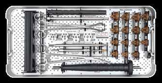
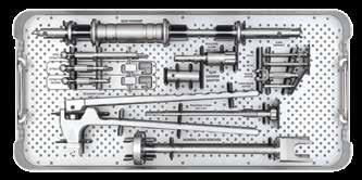
46 Catalog Information Instrument Sets Tray 1 General Glenoid Tray Tray No Cat. No. Part No. Description Qty Glenoid Template Forceps Glenoid Template Glenoid Template Glenoid Template Glenoid Template Drill Guide Holder Kirschner Guide Wire 3mm 3 Cat. No. Part No. Description Qty Drill with Stop 5.5mm Drive Shaft Slotted Tube Glenoid Reamer 1 Segmented, 30mm Glenoid Reamer 1 Segmented, 36mm Glenoid Reamer Segmented, 42mm 1 44
47 Tray 2 Cemented Glenoid Tray Tray No Cat. No. Part No. Description Qty Trial Glenoid Trial Glenoid Trial Glenoid Trial Glenoid Trial Glenoid Trial Glenoid Trial Glenoid Trial Glenoid Trial Glenoid Trial Glenoid Trial Glenoid Trial Glenoid Trial Glenoid Trial Glenoid Trial Glenoid Cat. No. Part No. Description Qty Glenoid Impactor Centering Peg Inserter Trial Glenoid Extractor Centering Peg 5.5mm Centering Peg 6.5mm Glenoid Drill Guide Glenoid Drill Guide Glenoid Drill Guide Glenoid Drill Guide Cannulated Drill 6.5/3mm Drill with Stop 5.5mm Flexible Shaft with Quick 1 Couple Glenoid Holder Glenoid Holding Block 1 45

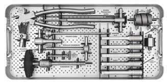
48 Catalog Information Instrument Sets Tray 3 General Humeral Tray Tray No Cat. No. Part No. Description Qty Rasp Adapter Spacer Awl Handle Awl Stem Rasp Stem Rasp Stem Rasp Stem Rasp Stem Rasp Stem Rasp Stem Rasp 5* 1 Cat. No. Part No. Description Qty Trial Humeral Stem Trial Humeral Stem Trial Humeral Stem Trial Humeral Stem Trial Humeral Stem Trial Humeral Stem Trial Humeral Stem Trial Humeral Stem Trial Humeral Stem Trial Humeral Stem 5* 1 Tray 4 General Humeral Tray 2 Tray No Cat. No. Part No. Description Qty Connection Screw (2 Parts) Connection Screw Set Mounting Clamp Inserter Inserter Inserter Inserter Cat. No. Part No. Description Qty Inserter Holding Screw T-Handle Modular Screw Driver Screw Driver Stepped T Torque Screwdriver 3/6NM 1 *available as part of Set no
49 Tray 5 Humeral Trials Tray Tray No Cat. No. Part No. Description Qty Body Adapter 30mm Body Adapter 35mm Body Adapter 40mm Trial Body 30mm Trial Body 35mm Trial Body 40mm Trial Monoblock Stem 02/ Trial Monoblock Stem 02/ Trial Monoblock Stem 02/ Primary Alignment Disc 1 Cat. No. Part No. Description Qty Sleeve Alignment Disc Trial Inclination Set 20mm Trial Inclination Set 22mm Trial Inclination Set 24mm Trial Inclination Set 26mm Resection Stylus Impactor for Monoblock Holding Fork Backtable Holding Block Screw Remover T Screw Remover Old Std Body SW3.5 47


50 Catalog Information Instrument Sets Tray 6 Proximal Standard Tray No Cat. No. Part No. Description Qty Sleeve/Head Impactor Trial HD R21/ Trial HD R22/ Trial HD R23/ Trial HD R24/ Trial HD R25/ Trial HD R26/ Trial HD R27/ Trial HD R28/ Trial HD R19/+2 1 Cat. No. Part No. Description Qty Trial HD R20/ Trial HD R21/ Trial HD R22/ Trial HD R23/ Trial HD R24/ Trial HD R25/ Trial HD R26/ Trial HD R27/ Trial HD R28/ Compatibility Chart 1 Tray 7 Revision Tray Tray No Cat. No. Part No. Description Qty Slap Hammer Screwdriver Bit SW Screwdriver Bit SW G.S. Release Adapter G.S. Screw Loosening Adapter 1 Cat. No. Part No. Description Qty Release Clamp (3-part) Slap Hammer Adapter Stem Extractor Extractor Extractor Reverse Humeral Head Remover 1 48
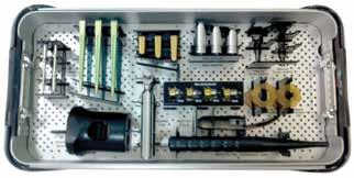
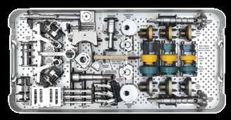
51 Supplemental Reverse Instrument Set Set no Tray 8 Stem Reverse Tray No Cat. No. Part No. Description Qty Reverse Humeral 1 Reamer ø Reverse Humeral Reamer ø Trial Reverse Body 36/5mm Trial Reverse Body 36/10mm Trial Reverse Body 36/15mm Trial Reverse Body 42/5mm Trial Reverse Body 42/10mm Trial Reverse Body 42/15mm Trial Insert 36/6mm Trial Insert 36/9mm Trial Insert 36/12mm Trial Insert 42/6mm Trial Insert 42/9mm Trial Insert 42/12mm Reverse Orientation 1 Device ø Reverse Orientation 1 Device ø Rev. Body Loosening Adaptor ø36 1 Cat. No. Part No. Description Qty Rev. Body Loosening 1 Adaptor ø Trial Insert Extractor Reverse Body 1 Mounting Adaptor Stem Extension Humeral Cut Block Reverse Cutting Device Rev. Reamer Guide 1 Fixation Device Reamer Guide 5mm Reamer Guide 10mm Reamer Guide 15mm Reverse Hollow Reamer Reverse Cutting Adaptor Right Reverse Cutting Adaptor Left Orientation Pins Cut Block Pins Sleeve to Cutting Device Adapter Cut Block Pins 2 49

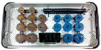
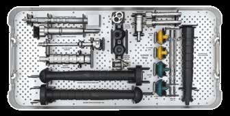
52 Catalog Information Instrument Sets Tray 9 Glenoid Reverse Tray No Cat. No. Part No. Description Qty Glenoid Baseplate 1 Impactor Drill Sleeve Ø4mm Drill Ø4mm Trial Glenosphere Centric Trial Glenosphere Centric Trial Glenosphere Eccentric Trial Glenosphere Eccentric Glenosphere Mounting 1 Adaptor Glenosphere Drill Guide Rev. Body Loosening Adapter ø42 1 Cat. No. Part No. Description Qty Centric Glenosphere 1 Adaptor Eccentric Glenosphere 1 Adaptor Glenoid Central Reamer Glenoid Peripheral Reamer Trail Fixation Screw Inserter Fixation Screw Inserter Inserter Glenosphere Impactor PE Insert 36mm Impactor PE Insert 42mm 1 50
53 Notes
54 Notes
55
56 Smith & Nephew, Inc Goodlett Farms Parkway Cordova, TN USA Manufacturer Smith & Nephew Orthopaedics AG Oberneuhofstrasse 10d 6340 Baar Switzerland Telephone: Information: Orders/inquiries: Trademark of Smith & Nephew. Reg. US Pat. & TM Off. All Trademarks acknowledged 2013 Smith & Nephew. All rights reserved V1 11/13
PROMOS STANDARD Surgical Technique
 Surgical Technique PROMOS STANDARD Surgical Technique Table of Contents Introduction... 1 Indications... 2 Contraindications... 2 Preoperative planning... 3 Patient positioning... 4 Surgical Technique...
This surgical technique describes how to perform an anatomic total shoulder arthroplasty implanting a short stem.
 INTRODUCTION This surgical technique describes how to perform an anatomic total shoulder arthroplasty implanting a short stem. CAUTION Federal law (USA) restricts this device to sale distribution and use
ANATOMIC SHOULDER ARTHROPLASTY
 ANATOMIC SHOULDER ARTHROPLASTY INTRODUCTION This surgical technique describes how to perform an anatomic shoulder arthroplasty implanting a cemented pegged glenoid baseplate. CAUTION Federal law (USA)
Surgical Technique. *smith&nephew. PROMOS STANDARD Modular Shoulder System
 Surgical Technique *smith&nephew PROMOS STANDARD Modular Shoulder System PROMOS STANDARD Table of Contents Introduction... 3 Indications, Contraindications and Risk Factors... 4 Case Studies... 5 Preoperative
Surgical Technique. Proximal Humerus Locking Plate
 Surgical Technique Proximal Humerus Locking Plate PERI-LOC Upper Extremity Locked Plating System 3.5mm & 4.5mm Proximal Humerus Locking PlatesCatalog Infor Table of Contents Introduction.........................................................2
REVERSE SHOULDER ARTHROPLASTY
 REVERSE SHOULDER ARTHROPLASTY 1 INTRODUCTION REVERSE SHOULDER ARTHROPLASTY This surgical technique describes how to perform a reverse total shoulder arthroplasty implanting a pegged glenoid baseplate.
COMPLETE, CONVERTIBLE, INNOVATIVE. Surgical Technique REVERSE SHOULDER ARTHROPLASY
 COMPLETE, CONVERTIBLE, INNOVATIVE Surgical Technique Joint Spine Sports Med REVERSE SHOULDER ARTHROPLASY Reverse Shoulder Arthroplasty Surgical Technique 2 INDEX 1. INTRODUCTION 4 1.1 Indications of use
TABLE OF CONTENTS SURGICAL TECHNIQUE 1 POST-OPERATIVE REHABILITATION 18. pages 1 RADIOLOGICAL ASSESSMENT 1 2 PATIENT POSITIONING 1
 TABLE OF CONTENTS SURGICAL TECHNIQUE 1 1 RADIOLOGICAL ASSESSMENT 1 2 PATIENT POSITIONING 1 3 DELTO-PECTORAL APPROACH 2 4 HUMERAL HEAD OSTEOTOMY 6 5 CHOICE OF HUMERAL INCLINATION AND RETROVERSION 7 pages
3. PATIENT POSITIONING & FRACTURE REDUCTION 3 8. DISTAL GUIDED LOCKING FOR PROXIMAL NAIL PROXIMAL LOCKING FOR LONG NAIL 13
 Contents IMPLANT FEATURES 2 1. INDICATIONS 3 2. PRE-OPERATIVE PLANNING 3 3. PATIENT POSITIONING & FRACTURE REDUCTION 3 4. INCISION 4 5. ENTRY POINT 4-6 6. PROXIMAL NAIL INSERTION 6-7 7. PROXIMAL LOCKING
The Bio-Modular Choice Shoulder System,
 Surgical Technique The Bio-Modular Choice Shoulder System, designed for both total and hemiarthroplasty of the shoulder, has enjoyed nearly two decades of clinical success. The variety of head types and
SURGICAL TECHNIQUE DUAL-PLATFORM SHOULDER ARTHROPLASTY.
 SURGICAL TECHNIQUE DUAL-PLATFORM SHOULDER ARTHROPLASTY www.fhortho.com SURGICAL TECHNIQUE REFERENCE NUMBERS HUMERAL STEMS REFERENCE DIAMETER HEIGHT 267 360 Ø 06 100 265 102 Ø 08 120 265 103 Ø 08 170 265
Zimmer NexGen MIS Tibial Component. Cemented Surgical Technique IMAGE TO COME
 Zimmer NexGen MIS Tibial Component Cemented Surgical Technique IMAGE TO COME Zimmer NexGen MIS Tibial Component Cemented Surgical Technique 1 Zimmer NexGen MIS Tibial Component Cemented Surgical Technique
System. Humeral Nail. Surgical Technique
 System Humeral Nail Surgical Technique Contents IMPLANT FEATURES 2 1. INDICATIONS 3 2. PRE-OPERATIVE PLANNING 3 3. PATIENT POSITIONING & FRACTURE REDUCTION 3 4. INCISION 4 5. ENTRY POINT 4-6 6. PROXIMAL
Anatomic and Reverse Shoulder. Surgical Technique
 Anatomic and Reverse Shoulder Surgical Technique CONTENTS KEY SURGICAL STEPS GLOBAL UNITE Platform Shoulder System Key Surgical Steps: Anatomic 4 GLOBAL UNITE Platform Shoulder System Key Surgical Steps:
GLENOID SURGICAL TECHNIQUE
 UP. EXTREMITY Dual-Platform Shoulder Prosthesis GLENOID SURGICAL TECHNIQUE ANATOMICAL REVERSE SURGICAL TECHNIQUE REFERENCE NUMBERS HUMERAL STEM REFERENCE DIAMETER HEIGHT 267 360 Ø 06 100 265 102 Ø 08 120
TORNIER BIO-RSA. Bony Increased Offset - Reversed Shoulder Arthroplasty SURGICAL TECHNIQUE
 TORNIER BIO-RSA Bony Increased Offset - Reversed Shoulder Arthroplasty SURGICAL TECHNIQUE 2 Table of Contents: Concept...4 Bony Increased Offset Reversed Shoulder Arthroplasty (BIO-RSA ) Concept...4 Surgical
Surgical. Technique. AEQUALIS Spherical Base Glenoid. Shoulder Prosthesis.
 Surgical Technique Shoulder Prosthesis AEQUALIS Spherical Base Glenoid www.tornier.com CONTENTS CONTENTS 1. Subscapularis 2. Anterior capsule 3. Humeral protector 4. Inserting retractors 1. DESIGN FEATURES
Distal Cut First Femoral Preparation
 Surgical Technique Distal Cut First Femoral Preparation Primary Total Knee Arthroplasty LEGION Total Knee System Femoral preparation Contents Introduction...3 DCF femoral highlights...4 Preoperative planning...6
Clinical Evaluation Surgical Technique
 Clinical Evaluation Surgical Technique Table of Contents EMPERION Specifications 3 EMPERION Surgical Technique 9 EMPERION Catalog 18 Nota Bene: This technique description herein is made available to the
Surgical Technique. VISIONAIRE Disposable Instruments for the LEGION Total Knee System
 Surgical Technique VISIONAIRE Disposable Instruments for the LEGION Total Knee System VISIONAIRE and LEGION Disposable instrument technique* Note: All disposable instruments are interchangeable with the
ANATOMIC SURGICAL TECHNIQUE. 5 in 1. Conventional instrumentation 07/11/2013
 ANATOMIC SURGICAL TECHNIQUE 5 in 1 Conventional instrumentation PRO.GB.933/1.0 Octobre 2013 2 Tibial step 3 Intramedullary technique - Based on the preoperative plan, drill the medullary canal with the
Surgical Technique. CONQUEST FN Femoral Neck Fracture System
 Surgical Technique CONQUEST FN Femoral Neck Fracture System Table of Contents Introduction... 3 Indications... 3 Product Overview... 4 Surgical Technique... 5 Patient Positioning... 5 Reduce the Fracture...
Surgical Technique. VISIONAIRE FastPak Instruments for the LEGION Total Knee System
 Surgical Technique VISIONAIRE FastPak Instruments for the LEGION Total Knee System VISIONAIRE FastPak for LEGION Instrument Technique* Nota Bene The technique description herein is made available to the
MIS Cemented Tibial Component
 MIS Cemented Tibial Component NexGen Complete Knee Solution Surgical Technique Table of Contents Surgical Exposure... 2 Finish the Tibia... 2 Position Based on Anatomic Landmarks... 3 Lateral Posterior
Technique Guide. 3.5 mm LCP Periarticular Proximal Humerus Plate. Part of the Synthes locking compression plate (LCP) system.
 system.") Technique Guide 3.5 mm LCP Periarticular Proximal Humerus Plate. Part of the Synthes locking compression plate (LCP) system. Table of Contents Introduction 3.5 mm LCP Proximal Humerus Plate 2 AO Principles
Technique Guide 3.5 mm LCP Periarticular Proximal Humerus Plate. Part of the Synthes locking compression plate (LCP) system. Table of Contents Introduction 3.5 mm LCP Proximal Humerus Plate 2 AO Principles
U2 PSA. Revision Knee. Surgical Protocol
 U2 PSA TM Revision Knee Surgical Protocol Table of Contents 1 Component Removal... 1 2 Tibial Preparation... 1 2.1 Tibial Canal Preparation... 1 2.2 Proximal Tibial Resection... 2 2.3 Non Offset Tibial
Extramedullary Tibial Preparation
 Surgical Technique Extramedullary Tibial Preparation Primary Total Knee Arthroplasty LEGION Total Knee System Extramedullary tibial preparation Contents Introduction...2 EM tibial highlights...3 Preoperative
Technique Guide. Epoca Revision Instrument Set. For extraction and revision of Epoca shoulder implants.
 Technique Guide Epoca Revision Instrument Set. For extraction and revision of Epoca shoulder implants. Table of Contents Introduction Epoca Revision Instrument Set 2 Implantation of a Long or Extra-long
Surgical Technique. Hinge Disassembly and Rebuild Technique
 Surgical Technique Hinge Disassembly and Rebuild Technique Revision Knee Arthroplasty Surgical Technique LEGION HK Hinge Knee System Introduction The LEGION HK Hinge Knee System has been designed as an
Orthopedic Bone Nail System - Distal Femoral Nail Surgical Technique Manual
 Orthopedic Bone Nail System - Distal Femoral Nail Surgical Technique Manual Note: The surgical procedures should be performed under the guidance of qualified skilled orthopedic surgeons, and this surgical
Surgical Technique Final Trial Reduction and Component Implantation of
 Surgical Technique Final Trial Reduction and Component Implantation of TC *smith&nephew TC-PLUS PRIMARY Mobile Bearing TC-PLUS PRIMARY Mobile Bearing Final Trial Reduction and Component Implantation of
Open reduction; plate fixation 1 Principles
 Executive Editor: Peter Trafton Authors: Martin Jaeger, Frankie Leung, Wilson Li Proximal humerus 11-A2 Open reduction, plate fixation Search search... Shortcuts All Preparations All Approaches All Reductions
S H O U L D E R Solutions by Tornier. BIO-RSA TM ANGled SURGICAL TECHNIQUE. BIO-RSA Angled. surgical technique
 S H O U L D E R Solutions by Tornier BIO-RSA TM ANGled SURGICAL TECHNIQUE BIO-RSA Angled Bony increased offset - reversed shoulder arthroplasty surgical technique BIO-RSA TM ANGled SURGICAL TECHNIQUE BIO-RSA
TABLE OF CONTENTS. 2 (8144 Rev 2)
") 1 (8144 Rev 2) TABLE OF CONTENTS Introduction Conventus CAGE TM - Proximal Humerus...3 Indications and Contraindications...4 Surgical Summary...5 Patient Positioning & Approach...6 Surgical Technique Plate
1 (8144 Rev 2) TABLE OF CONTENTS Introduction Conventus CAGE TM - Proximal Humerus...3 Indications and Contraindications...4 Surgical Summary...5 Patient Positioning & Approach...6 Surgical Technique Plate
Anatomical Shoulder System
 Anatomical Shoulder System Adjustable. Convertible. Compatible. Anatomical Shoulder System by Zimmer This unique system is like an individually produced prosthesis specifically designed for each patient.
Surgical Technique. Clavicle Locking Plate
 Surgical Technique Clavicle Locking Plate PERI-LOC Locked Plating System Clavicle Locking Plate Surgical Technique Table of Contents Introduction...2 Indications...3 Plate Features...3 Patient Positioning...4
Anatomical Shoulder Glenoid. Surgical Technique
 Anatomical Shoulder Glenoid Surgical Technique Anatomical Shoulder Glenoid Surgical Technique 3 Table of Contents Glenoid Preparation Surgical Steps 4 Anatomical Shoulder Glenoid 4 Glenoid Components
HUMERISTM. Cementless ANATOMICAL and REVERSIBLE SURGICAL TECHNIQUE
 HUMERISTM Cementless ANATOMICAL and REVERSIBLE Hemi or Total Reversible SURGICAL TECHNIQUE CONTENTS - Device descriptionpage 0 - Intended use / indicationspage 04 - Warnings and precautions page 04 - Anatomical
ReUnion RSA Shoulder System
 ReUnion RSA Shoulder System Reverse Surgical Protocol This document is intended to be used by healthcare professionals only. ReUnion RSA Reverse Shoulder Surgical Protocol Table of Contents Surgical Technique
Surgical Technique. Targeter Systems Overview
 Surgical Technique Targeter Systems Overview PERI-LOC Locked Plating System Targeter Systems Overview Table of contents Product overview... 2 Introduction... 2 Indications... 2 Design features and benefits...
The new removable head option. Anatomical Shoulder System
 The new removable head option Anatomical Shoulder System Anatomical Shoulder System by Zimmer This unique system offers the advantages of a custom-made prosthesis. The modularity and design of the Anatomical
Surgical Technique. Intramedullary locked Nailing With Screws for Humerus Fractures Solid/Cannulated. Humeral Interlocking Nail.
 Screws for Humerus Fractures Surgical Technique Humeral Interlocking Nail Approved by Humerus Nail Kit Code 08050001 Contents Introduction Implant design Indications Pre-operative planning Patient positioning
TORNIER SIMPLICITI. Shoulder System SURGICAL TECHNIQUE
 TORNIER SIMPLICITI Shoulder System SURGICAL TECHNIQUE Table of Contents: Indications & Contraindications... 4 System Compatibility & Pre-operative Planning... 4 Humeral Head Resection... 6 Freehand Resection
Surgical Technique VPLWK QHSKHZ 1$126 1HFN 3UHVHUYLQJ +LS 6WHP 1716-e_NANOS_OPT.indd :27
 Surgical Technique NANOS Neck Preserving Hip Stem Table of Contents Introduction... 3 Development/Concept... 4 Indications/Contraindications... 5 Preoperative Planning... 5 Surgical Technique... 6 Prosthesis
Surgical Technique. Anterolateral and Medial Distal Tibia Locking Plates
 Surgical Technique Anterolateral and Medial Distal Tibia Locking Plates PERI-LOC Periarticular Locked Plating System Anterolateral and Medial Distal Tibia Locking Plates Surgical Technique Contents Product
Encina Taper Stem. Stinson Orthopedics Inc. 303 Twin Dolphin Drive, Suite 600 Redwood City, CA
 Stinson Orthopedics Inc. 303 Twin Dolphin Drive, Suite 600 Redwood City, CA 94065 info@stinsonortho.com www.stinsonortho.com Table of Contents Introduction 3 Features 4 Surgical Technique 5 Preoperative
THE NATURAL FIT. Surgical Technique. Hip Knee Spine Navigation
 THE NATURAL FIT Surgical Technique Hip Knee Spine Navigation MiniMAX Surgical Technique Hip Knee Spine Navigation INTRODUCTION The MiniMAX TM is a cementless anatomic stem available in 9 right sizes and
Polarus 3 Solution Plates and Nails. Surgical Technique 4.3. Screws
 Polarus 3 Solution Plates and Nails Surgical Technique 4.3 mm Screws Acumed is a global leader of innovative orthopaedic and medical solutions. We are dedicated to developing products, service methods,
ReUnion. RSA Reverse Shoulder Arthroplasty System. Operative technique
 ReUnion RSA Reverse Shoulder Arthroplasty System Operative technique ReUnion RSA Shoulder System Operative technique ReUnion RSA Reverse Shoulder Arthroplasty System Surgical technique 6 Patient positioning...
Intramedullary Tibial Preparation
 Surgical Technique Intramedullary Tibial Preparation Primary Total Knee Arthroplasty LEGION Total Knee System Intramedullary tibial preparation Contents Introduction...2 IM tibial highlights...3 Preoperative
Solutions by Tornier. surgical technique
 S H O U L D E R Solutions by Tornier S I M P L I C I T I S U R G I C A L T E C H N I Q U E S H O U L D E R S Y S T E M surgical technique S I M P L I C I T I S H O U L D E R S Y S T E M S U R G I C A L
Knee Surgical Technique
 Knee Surgical Technique COMPASS Universal Hinge by Jimmy Tucker, M.D. Orthopaedic Surgeon Director, Arkansas Sports Medicine, P.A. Little Rock, Arkansas Table of contents Design features 3 Indications
humerus InSafeLOCK Nail
 humerus InSafeLOCK Nail Introduction Content Humerus InSafeLOCK Nail is an innovative intramedullary nailing system, developed for humerus problems. Humerus fractures have 5-6 % incidence of all bone fractures.
Surgical Technique. Distal Humerus Locking Plate
 Surgical Technique Distal Humerus Locking Plate PERI-LOC Locked Plating System Distal Humerus Locking Plate Surgical Technique Table of Contents Introduction...2 Indications...3 Plate Features...3 Patient
Surgical Technique International Version. Clavicle Locking Plate
 Surgical Technique International Version Clavicle Locking Plate PERI-LOC Upper Extremity Locked Plating System Clavicle Surgical Techniquefor Table of Contents Introduction........................................................2
Aequalis Press-Fit. Shoulder Prosthesis. Surgical Technique
 Aequalis Press-Fit Shoulder Prosthesis Surgical Technique SURGICAL TECHNIQUE RATIONALE OF THE AEQUALIS PRESS-FIT PROSTHESIS p. 1 THE AEQUALIS PRESS-FIT PROSTHESIS p. 2 SURGICAL TECHNIQUE p. 3-21 1. A detailed
Anatomical Shoulder Fracture. Surgical Technique
 Anatomical Shoulder Fracture Surgical Technique Anatomical Shoulder Fracture Surgical Technique 3 Surgical Technique Anatomical Shoulder Fracture Table of Contents Indications 4 Preoperative Planning
Humerus Block. Discontinued December 2016 DSEM/TRM/0115/0296(1) Surgical Technique. This publication is not intended for distribution in the USA.
 Surgical Technique. This publication is not intended for distribution in the USA.") Humerus Block Surgical Technique Discontinued December 2016 DSEM/TRM/0115/0296(1) This publication is not intended for distribution in the USA. Instruments and implants approved by the AO Foundation. Contents
Humerus Block Surgical Technique Discontinued December 2016 DSEM/TRM/0115/0296(1) This publication is not intended for distribution in the USA. Instruments and implants approved by the AO Foundation. Contents
Surgical Technique Guide PANTERA. Proximal Humerus Fracture Fixation Plate System
 Surgical Technique Guide PANTERA Proximal Humerus Fracture Fixation Plate System Installing the PANTERA is a 4-Step Process: The following technique is designed to optimize the surgical exercise. Step
Table of contents. Introduction... 3 Indications... 3 Contraindications... 3 TRIGEN Humeral Nail Specifications... 6
 Surgical Technique Table of contents Introduction... 3 Indications... 3 Contraindications... 3 TRIGEN Humeral Nail Specifications... 6 Surgical Technique Patient positioning... 7 Establish the incision
SURGICAL TECHNIQUE GUIDE
 DANGER indicates an imminently hazardous situation which, if not avoided, will result in death or serious injury. WARNING indicates a potentially hazardous situation which, if not avoided, could result
AcUMEDr. FoREARM ROD SYSTEM
 AcUMEDr FoREARM ROD SYSTEM FoREARM ROD SYSTEM Since 1988 Acumed has been designing solutions to the demanding situations facing orthopedic surgeons, hospitals and their patients. Our strategy has been
TM HUMELOCK II. Cemented. Hemi / Trauma. Total / Primary SURGICAL TECHNIQUE
 TM HUMELOCK II Cemented Hemi / Trauma SURGICAL TECHNIQUE Total / Primary CONTENTS - Surgical technique Humerus : Degenerative...page 0 - Surgical technique Glenoid...page 0 - Surgical technique Humerus
Operative Technique Resurfacing Humeral Head
 EXACTECH SHOULDER Operative Technique Resurfacing Humeral Head TABLE OF CONTENTS INTRODUCTION... 1 SYSTEM SPECIFICATIONS... 1 PATIENT POSITIONING... 2 SURGICAL APPROACH... 2 SIZING THE HUMERUS FOR A RESURFACING
Conventus CAGE PH Surgical Techniques
 Conventus CAGE PH Surgical Techniques Conventus Orthopaedics The Conventus CAGE PH (PH Cage) is a permanent implant comprised of an expandable scaffold, made from nitinol and titanium, which is deployed
Surgical Technique. Olecranon Locking Plate
 Surgical Technique Olecranon Locking Plate PERI-LOC Locked Plating System Olecranon Locking Plate Surgical Techniquealog Infor Table of Contents Introduction...2 Indications...3 Plate Features...3 Patient
Surgical. Technique. Aequalis Press-Fit. Shoulder Prosthesis.
 Surgical Technique Shoulder Prosthesis www.tornier.com TABLE OF CONTENTS 1. Preoperative planning 2. Patient positioning 3. Delto-pectoral approach 4. Humeral head osteotomy 5. Reaming the humeral shaft
Humeral SuturePlate. Surgical Technique
 Humeral SuturePlate Surgical Technique The humeral SuturePlate is an anatomically designed, low profile, titanium polyaxial locking plate and screw system. Multiple chamfered suture eyelets along the margin
Anatomical Shoulder System
 Anatomical Shoulder System Surgical Technique Adjustable. Convertible. Compatible. Disclaimer This document is intended exclusively for physicians and is not intended for laypersons. Information on the
Double Engine Orthopedic Bone Nail System Universal Humeral Nail
 Double Engine Orthopedic Bone Nail System ----------- Universal Humeral Nail Surgical Technique Manual Note: The surgical procedures should be performed under the guidance of qualified skilled orthopedic
URSA HEMI-SHOULDER ARTHROPLASTY B I O T E K
 URSA HEMI-SHOULDER ARTHROPLASTY SURGICAL TECHNIQUE B I O T E K 2 Surgical Position Once general anesthesia has been satisfactorily induced, or a supraclavicular nerve block has been given, the patient
Zimmer NexGen Trabecular Metal Tibial Tray
 Zimmer NexGen Trabecular Metal Tibial Tray Surgical Technique Zimmer NexGen Trabecular Metal Tibial Tray Surgical Technique Give Bone A Solid Hold Zimmer NexGen Trabecular Metal Tibial Tray Surgical Technique
Surgical Technique. 3.5mm and 4.5mm Lateral Proximal Tibia Locking Plates
 Surgical Technique 3.5mm and 4.5mm Lateral Proximal Tibia Locking Plates PERI-LOC Periarticular Locked Plating System 3.5mm and 4.5mm Lateral Proximal Tibia Locking Plate Surgical Technique Contents Product
AEQUALIS ADJUSTABLE REVERSED
 TORNIER AEQUALIS ADJUSTABLE REVERSED Shoulder System SURGICAL TECHNIQUE 2 Table of Contents: Indications/Contraindications...5 Pre-Operative Planning...6 Delto-Pectoral Humeral Exposure...7 Supero-Lateral
Surgical Technique Final Trial Reduction and Component Implantation of
 Surgical Technique Final Trial Reduction and Component Implantation of TC *smith&nephew TC-PLUS PRIMARY Fixed Bearing TC-PLUS PRIMARY Fixed Bearing Final Trial Reduction and Component Implantation of
EXACTECH EXTREMITIES. Operative Technique. Preserve Stem. Surgeon focused. Patient driven. TM
 EXACTECH EXTREMITIES Operative Technique Preserve Stem Surgeon focused. Patient driven. TM TABLE OF CONTENTS INTRODUCTION...1 DETAILED OPERATIVE TECHNIQUE...2 PREOPERATIVE PLANNING/PATIENT POSITIONING...2
Surgical Technique. Forearm Fracture Solutions
 Surgical Technique Forearm Fracture Solutions Acumed is a global leader of innovative orthopaedic and medical solutions. We are dedicated to developing products, service methods, and approaches that improve
Polarus 3 Solution Plates and Nails
 Surgical Technique Polarus 3 Solution Plates and Nails Acumed is a global leader of innovative orthopaedic and medical solutions. We are dedicated to developing products, service methods, and approaches
AEQUALIS PERFORM + REVERSED
 TO R N I E R AEQUALIS PERFORM + REVERSED Glenoid WEDGED AUGMENT SURGIC AL TECHNIQUE Table of Contents: AEQUALIS PERFORM + REVERSED Glenoid...3 Overview...3 Indications/Contraindications...4 Pre-Operative
Approach Patients with Confidence
 Surgical Technique Approach Patients with Confidence The ACTIS Total Hip System is the first DePuy Synthes stem specifically designed to be utilized with tissue sparing approaches, such as the anterior
OPERATIVE TECHNIQUE GALAXY FIXATION SHOULDER
 OPERATIVE TECHNIQUE GALAXY FIXATION SHOULDER cop2 OPERATIVE TECHNIQUE INTRODUCTION 1 FEATURES OF SHOULDER COMPONENTS 2 EQUIPMENT REQUIRED 5 PREOPERATIVE PLANNING 6 SURGICAL PROCEDURE 8 POST OPERATIVE MANAGEMENT
*smith&nephew CONTOUR
 Surgical Technique *smith&nephew CONTOUR Acetabular Rings CONTOUR Acetabular Rings Surgical technique completed in conjunction with Joseph Schatzker MD, BSc (Med.), FRCS (C) Allan E. Gross, MD, FRCS (C)
Zimmer Trabecular Metal Ankle Interpositional Spacer and Trabecular Metal Ankle Fusion Spacer
 Zimmer Trabecular Metal Ankle Interpositional Spacer and Trabecular Metal Ankle Fusion Spacer Surgical Technique 2 Zimmer Trabecular Metal Ankle Interpositional Spacer and Trabecular Metal Ankle Fusion
Affinis Total Shoulder Prosthesis. Surgical technique
 Affinis Total Shoulder Prosthesis Surgical technique Contents Introduction 4 Total shoulder prosthesis 4 1. Indications 5 1.1 Indications 5 1.2 Contraindications 5 2. Preoperative planning 6 3. Surgical
ASHCOM Shoulder. Anatomical Shoulder Stems meet Comprehensive Reverse. Surgical Technique
 ASHCOM Shoulder Anatomical Shoulder Stems meet Comprehensive Reverse Surgical Technique Table of Contents Indications and Contraindications... 2 Surgical Technique Summary... 3 Humeral Head Resection...
EXACTECH KNEE. Operative Technique ADDENDUM. Metaphyseal Cones. Surgeon focused. Patient driven. TM
 EXACTECH KNEE Operative Technique ADDENDUM Metaphyseal Cones Surgeon focused. Patient driven. TM TABLE OF CONTENTS INTRODUCTION...1 DESCRIPTION...1 DETAILED OPERATIVE TECHNIQUE Initial Preparation and
HUMELOCK. REVERSED Cemented SURGICAL TECHNIQUE SUPERIOR GLENOID WEAR PRIMARY, REVISION & TRAUMA
 HUMELOCK TM REVERSED Cemented SUPERIOR GLENOID WEAR PRIMARY, REVISION & TRAUMA SURGICAL TECHNIQUE CONTENTS - Device descriptionpage 0 - Intended use / Indicationspage 05 - Warnings and precautions page
Technique. Aequalis Resurfacing Humeral Head
 S u r g i c a l Technique Aequalis Resurfacing Humeral Head 1 The Aequalis Resurfacing Humeral Head has been developed in conjunction with Drew Miller, MD - Atlanta, GA. The Aequalis Resurfacing Humeral
Zimmer Periarticular Proximal Humeral Locking Plate
 Zimmer Periarticular Proximal Humeral Locking Plate Surgical Technique The Science of the Landscape Zimmer Periarticular Proximal Humeral Locking Plate 1 Surgical Technique Table of Contents Introduction
SURGICAL TECHNIQUE. Alpine Cementless Hip Stem
 SURGICAL TECHNIQUE Alpine Cementless Hip Stem The following technique is a general guide for the instrumentation of the Alpine Cementless Hip Stem. It is expected that the surgeon is already familiar with
GB UDRT061 25/07/06 9:30 Page 32. Surgical. Technique. Shoulder Prosthesis. Aequalis-Reversed
 GB UDRT061 25/07/06 9:30 Page 32 Surgical Technique Shoulder Prosthesis Aequalis-Reversed GB UDRT061 25/07/06 9:29 Page 1 Table of Contents Aequalis-Reversed shoulder prosthesis Biomechanics, indications
Operative Technique Resurfacing Humeral Head
 EXACTECH SHOULDER Operative Technique Resurfacing Humeral Head TABLE OF CONTENTS INTRODUCTION...1 RESURFACING HUMERAL HEAD...1 SYSTEM SPECIFICATIONS...1 DETAILED OPERATIVE TECHNIQUE...2 PATIENT POSITIONING...2
LCP Distal Humerus Plates
 The anatomic fixation system for the distal humerus with angular stability Surgical technique LCP Locking Compression Plate Contents Indications and contraindications 2 Implants 3 Instruments 5 Preparation
FACET WEDGE. Facet joint fixation device.
 FACET WEDGE. Facet joint fixation device. Technique Guide Synthes FACET WEDGE Technique Guide /44 Synthes FACET WEDGE Technique Guide /44 Table of Contents Introduction FACET WEDGE 3 AO Principles 4 Indications
28 Surgical Technique
 Surgical Technique 10 12 14 16 18 20 22 24 28 26 Technique described by James L. Guyton, MD Campbell Clinic Memphis, Tennessee James W. Harkess, MD Campbell Clinic Memphis, Tennessee David G. LaVelle,
Surgical Technique. Calcaneal Locking Plate
 Surgical Technique Calcaneal Locking Plate PERI-LOC Locked Plating System Calcaneal Locking Plate Surgical TechniqueCatalog Infor Table of Contents Introduction...2 Indications...3 Plate Features...3 Patient
TRIAL COMPONENTS SURGICAL TECHNIQUE REAMING THE TIBIAL AND FEMORAL INTRAMEDULLARY CANAL
 Ref. no. 99.27.2TRIALS TRIAL COMPONENTS SURGICAL TECHNIQUE CLINICAL INDICATION This technique is indicated in the case of revisions with significant bone loss when minimal or any resection of bone is required.
Zimmer PSI Shoulder Trabecular Metal Reverse Glenoid Base Plate. Surgical Technique
 Zimmer PSI Shoulder Trabecular Metal Reverse Glenoid Base Plate Surgical Technique Zimmer Patient Specific Shoulder - Trabecular Metal Reverse Glenoid Base Plate Surgical Technique Zimmer PSI Shoulder
Arcos Modular Femoral Revision System. Broach and Calcar Proximal Bodies Surgical Technique
 Arcos Modular Femoral Revision System Broach and Calcar Proximal Bodies Surgical Technique Table of Contents Pre-operative Planning...2 Patient Positioning and Surgical Approach...2 Removal of a Cemented