FACET WEDGE. Facet joint fixation device.
|
|
|
- Willis Parrish
- 5 years ago
- Views:
Transcription

1 FACET WEDGE. Facet joint fixation device. Technique Guide Synthes FACET WEDGE Technique Guide /44
2 Synthes FACET WEDGE Technique Guide /44
3 Table of Contents Introduction FACET WEDGE 3 AO Principles 4 Indications 5 Preoperative Planning and Preparation 6 Surgical Technique Patient Positioning 7 Access and Exposure 8 Insert K-Wire 0 Prepare facet joint 3 Proceed on contralateral side 5 Insert implant 6 Insert Screw 9 Remove implant holder 3 Finalizing construct 4 Implant removal 6 Product Information Implants 7 Filling volumes 7 Instruments 8 Assembly instructions 3 Disassembly instructions 3 Sets 36 Image intensifier control Warning This description alone does not provide sufficient background for direct use of the instrument set. Instruction by a surgeon experienced in handling these instruments is highly recommended. Reprocessing, Care and Maintenance of Synthes Instruments For general guidelines, function control and dismantling of multi-part instruments, please contact your local sales representative or refer to: Synthes FACET WEDGE Technique Guide 3/44
4 FACET WEDGE. Facet joint fixation device. Implant features K-Wire hole Enable guided insertion over K-Wire Rails Teeth stop translational motion and contact subchondral bone Low Profile Less muscle irritation. Profile height:.5 mm Implant shoulder Control insertion depth Screws Angle stable diverging locking screws for primary fixation Sizes Implant sizes to accommodate patient anatomy Perforations Create optimal fusion conditions Synthes FACET WEDGE Technique Guide 4/44
5 Instrument features The few required instruments are designed for ease of use. FACET WEDGE System FACET WEDGE allows fixation of a spinal segment through immobilization of the facet joints. Controlled K-Wire insertion through Facet Opener allowing guided surgical technique. Combined implant holder and screw guide leads to short OR time. The save surgical technique comprises following advantages: Atraumatic transmuscular approach Treatment of affected segment only Minimal exposure of radiation Less complication risks (stay away from dangerous structures such as nerves/vessels) Optimal fusion conditions through instruments for facet joint preparation and implant perforations. Synthes FACET WEDGE Technique Guide 5/44
6 AO Principles In 958, the AO formulated four basic principles, which have become the guidelines for internal fixation., They are: Anatomic reduction Fracture reduction and fixation to restore anatomical relationships. Stable fixation Stability by fixation or splintage, as the personality of the fracture and the injury requires. Preservation of blood supply Preservation of the blood supply to soft tissue and bone by careful handling. Early, active mobilization Early, active mobilization of the part and patient. Müller ME, M Allgöwer, R Schneider, H Willenegger. Manual of Internal Fixation. 3rd ed. Berlin Heidelberg New York: Springer. 99. Rüedi TP, RE Buckley, CG Moran. AO Principles of Fracture Management. nd ed. Stuttgart, New York: Thieme Synthes FACET WEDGE Technique Guide 6/44
7 Indications (and Contraindications) FACET WEDGE is intended for the fixation of the spine as an aid to fusion through immobilization of the facet joints, with or without bone graft, at single or multiple levels, from L to S. FACET WEDGE can be inserted minimal invasively either to augment other fusion techniques or as a stand-alone device for cases without segmental instability. Indications: Degenerative disc disease Degenerative facet joint disease (isolated facet based symptomatic back pain) Pseudarthrosis post anterior instrumentation Contraindications: In case of segmental instability, FACET WEDGE must be applied in combination with additional fixation Unilateral application, except in combination with pedicle screw fixation on the contralateral side Decompression techniques compromising the facets Spondylolisthesis Fracture or other instabilities of the posterior elements Tumor Acute or chronic systemic or localized spinal infections Synthes FACET WEDGE Technique Guide 7/44
8 Preoperative Planning and Preparation Preparation Required set(s) xxx Standard set xxx Basic set Optional set(s) MIS Support System Standard set contains all required instruments and implants. When Basic set is used, preparation and access instruments such as Dilators, Retractors, Rongeurs must be provided separately. These instruments can be found on the following Synthes sets: Set Art. No. Mipi Insight retractor Have all necessary imaging studies readily available to plan implant placement and visualize individual patient anatomy. Have all sets readily available prior to surgery. Optionally: Retractor frame can be attached to table fixation system e.g. MIS Support System Preoperative imaging may be useful to plan the trajectory of approach and identify patient morphology. Synthes FACET WEDGE Technique Guide 8/44


9 Patient positioning Position the patient Position the patient on a radiolucent OR table in the prone position. To obtain optimal visualization of the spine, the OR table should have enough clearance available for a fluoroscopic C-arm to rotate freely for AP, oblique and lateral views. Accurate visualization of the anatomic landmarks and fluoroscopic visualization of the facet joints are imperative for using the FACET WEDGE System.. Synthes FACET WEDGE Technique Guide 9/44

. The incision length should be at least 9 mm (initial opening of retractor) Separate the soft tissue and palpate the facet joint.")
10 Access and Exposure Approach Instrument(s) Dilator Ø.0/0.0 mm, for Kirschner Wire Ø.0 mm Dilatator ø0.0/3.0 z/ Dilatator ø3.0/6.0 z/ Dilatator ø6.0/9.0 z/ Retractor Frame, cranial/caudal Retractor Handle Retractor Blade with Clearance, right, length 40 mm Retractor Blade with Clearance, left, length 40 mm Retractor Blade with Clearance, right, length 60 mm Retractor Blade with Clearance, left, length 60 mm Oblique imaging is necessary to locate the correct operative level and define trajectory of the approach through identification of joint cavety (). The incision length should be at least 9 mm (initial opening of retractor) Separate the soft tissue and palpate the facet joint. Position K-Wire in the incision and fix it on the bony structure of the facet joint. Dilate soft tissue by inserting the smallest diameter dilator. Repeat with next larger diameter dilator until required dilation is achieved. Synthes FACET WEDGE Technique Guide 0/44


11 Access and Exposure Determine the appropriate retractor lengths of the blades from the depth indicators on the dilators (). Slide the retractor with the attached blades over the dilators until the blades contact the facet joint. Remove dilators and K-Wire. Distract and angle the blades sufficiently to obtain optimal exposure of the facet joint. Note: Refer to Insight Retractor Techique Guide ( ) for further information on how to use the Retractor. Synthes FACET WEDGE Technique Guide /44

 and visualize joint entry. If necessary, use a rongeur to remove any osteophytes ().")

12 Access and Exposure Open capsula Precaution: Visualize and prepare the facet joints including the removal of osteophytes to ensure the correct placement of the FACET WEDGE implant. Remove remaining soft tissue to visualize the facet joint capsula. Open capsule () and visualize joint entry. If necessary, use a rongeur to remove any osteophytes (). Note: Complete capsula resection may compromise the stability of the final construct. Therefore try to maintain as much capsula as possible. Warning: When opening the capsula, stay superficial to avoid bleeding of the branches of the segmental lumbar artery. Synthes FACET WEDGE Technique Guide /44
. Mobilization of the segment may be necessary to visually identify the facet joint entry.")
. Note: Facet Opener shall not be inserted beyond stop ().")
13 Insert K-Wire Open Facet Joint Instrument(s) Facet Opener, T-Handle, for Quick Coupling, Precaution: Before inserting K-Wire use Facet Opener to ensure proper insertion location. Assemble T-Handle and connect T-Handle to the Facet Opener (see page 37). Mobilization of the segment may be necessary to visually identify the facet joint entry. Gently insert Facet Opener with T-Handle manually into facet joint until the stop. Beware of the central positioning and correct angulation. Note: T-Handle orientation should match facet plane orientation (). Note: Facet Opener shall not be inserted beyond stop (). Gentle movements of the Facet Opener may help to verify correct placement in the joint. Warning: Facet Opener shall not be used to distract joint and/ or to rasp the joint. Synthes FACET WEDGE Technique Guide 3/44


 and insert K-Wire until Tamp contacts the T-Handle ().")
.")
. Note: K-Wire has to be inserted with Tamp.")
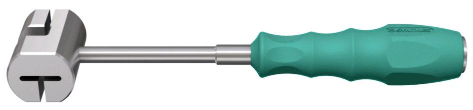
14 Insert K-Wire Insert K-Wire Instrument(s) Facet Opener, T-Handle, for Quick Coupling, Kirschner Wire Ø.0 mm, tip with thread, length 350 mm Tamp Ø.0 mm, for Kirschner Wire length 350 mm Combined Hammer, Ø.0 mm, Precaution: Only use the appropriate K-Wire from the system. Insert K-Wire into the canula of the Facet Opener. Slide Tamp over K-Wire () and insert K-Wire until Tamp contacts the T-Handle (). Controlled and light hammering on the Tamp may be required to advance K-Wire into the inferior articular process. Remove Tamp and Facet Opener (3). Oblique imaging in line with the K-Wire is necessary to confirm the central placement of the K-Wire in the facet joint (5). Note: K-Wire has to be inserted with Tamp. 3 4 Note: Tamp allows controlling K-Wire insertion depth. K-Wire is inserted 5mm deeper than the implant / Facet Opener. Note: Threaded part can be used as visual reference (4). Synthes FACET WEDGE Technique Guide 4/44

.")

15 Prepare facet joint Trial / Rasp insertion Instrument(s) T-Handle, for Quick Coupling, FACET WEDGE Trial Implant with Rasp, small, medium large Reamer for FACET WEDGE Combined Hammer, Ø.0 mm, Use the Trial / Rasp to remove the superficial cartilaginous layers of the joint surfaces to expose the bleeding bone. Slide Reamer over the Trial/ Rasp and connect assembled T-Handle to the appropriate Trial / Rasp size (see page 37). The Reamer locks into position when pulled back to allow visualization of cartilage removal. Slide Trial / Rasp over the K-Wire and insert Trial / Rasp into the facet joint. Controlled and light hammering on the Trial / Rasp may be required to advance Trial / Rasp until the stop (). Note: Make sure K-Wire is not pushed forward during Trial/ Rasp insertion. Note: T-Handle orientation should match facet plane orientation. Note: Trial/ Rasp shall not be inserted beyond stop (). Synthes FACET WEDGE Technique Guide 5/44

16 Prepare facet joint Remove cartilage Instrument(s) T-Handle, for Quick Coupling, FACET WEDGE Trial Implant with Rasp, small, medium large Reamer for FACET WEDGE Combined Hammer, Ø.0 mm, Retract Trial / Rasp from the facet joint. Controlled and light hammering on the Reamer may be required to retract Trial / Rasp. Repeat Trial / Rasp insertion and retraction - times to achieve desired cartilage removal. Important: Control the K-Wire while instrument retraction may be necessary to keep K-Wire in place. If the Trial / Rasp appears too small or too tight, try the next larger or smaller size until the most secure press fit is achieved. Precaution: The selection of a too large implant might lead to closing of the facet joint on the contralateral side. Important: Excessive removal of the subchondral bone may weaken the articular process and may result in pseudoarthrosis, segmental instability or facet fracture. Only apply manipulations in the direction of the facet joint. Apply gentle force using the Trial/ Rasp only. Synthes FACET WEDGE Technique Guide 6/44

.")


17 Prepare facet joint 3 Ream facet joint entry Instrument(s) T-Handle, for Quick Coupling, FACET WEDGE Trial Implant with Rasp, small, medium large Reamer for FACET WEDGE Combined Hammer, Ø.0 mm, When cartilage is removed and Trial / Rasp with optimal size is inserted into facet joint until the stop, push down and swivel Reamer to remove bone on the facet joint entry to create flat surface for optimal implant seating (). Note: Arrows and line indicate when Reamer has reached maximal depth (). If more reaming is required, Trial / Rasp need to be inserted deeper. Important: Make sure that an appropriate surface for implant fixation is created. Important: Control the K-Wire while instrument retraction may be necessary to keep K-Wire in place. Optionally: Reamer can be slided over the Trial / Rasp after Trial /Rasp is inserted and T-Handle is removed. Synthes FACET WEDGE Technique Guide 7/44

18 Proceed on contralateral side Proceed on contralateral side Instrument(s) Dilator Ø.0/0.0 mm, for Kirschner Wire Ø.0 mm Dilatator ø0.0/3.0 z/ Dilatator ø3.0/6.0 z/ Dilatator ø6.0/9.0 z/ Retractor Frame, cranial/caudal Retractor Handle Retractor Blade with Clearance, right, length 40 mm Retractor Blade with Clearance, left, length 40 mm Retractor Blade with Clearance, right, length 60 mm Retractor Blade with Clearance, left, length 60 mm Facet Opener, T-Handle, for Quick Coupling, Kirschner Wire Ø.0 mm, tip with thread, length 350 mm Tamp Ø.0 mm, for Kirschner Wire length 350 mm T-Handle, for Quick Coupling, FACET WEDGE Trial Implant with Rasp, small, medium large Reamer for FACET WEDGE Combined Hammer, Ø.0 mm, After reaming is done, remove T-Handle and Reamer but keep Trial / Rasp in situ. Precaution: Proceed on contra lateral side to avoid closure of the facet joint. Continue surgical procedure on contralateral side by repeating the following above described steps: Access and Exposure (page 0) Insert K-Wire (page 3) Prepare facet joint (page 5) Synthes FACET WEDGE Technique Guide 8/44

.")
.")

19 Insert Implant Optional: Pack implant with bone graft Instrument(s) Loading Station for FACET WEDGE Cancellous Bone Impactor for FACET WEDGE Select the FACET WEDGE implant that corresponds to the used Trial / Rasp size in the previous step. Insert the selected implant into the appropriate place in the loading station (). Turn the loading station on its side and use the cancellous bone impactor to firmly pack the filling material such as bone graft or bone substitute into the implant perforations (). Make sure the implant is well placed in the packing block to avoid implant damage while bone graft filling (3). It is important to fill the implant until the filling material protrudes from its perforations in order to ensure optimal contact with the facet joint surfaces (4). 3 For more information about the filling volumes, see page 7 in this technique guide. 4 Synthes FACET WEDGE Technique Guide 9/44

. Slide the screw guide over the inner shaft.")
.")
20 Insert implant Connect implant holder to implant Instrument(s) Loading Station for FACET WEDGE Implant Holder for FACET WEDGE To connect the implant holder to the implant turn the loading station upwards again. Connect the shaft of the implant holder onto the implant (). Slide the screw guide over the inner shaft. Pull back the flat spring to allow screw guide to fully slide down the inner shaft (). If necessary, rotate the screw guide until the flat spring snaps into position (3). Screw the cap onto the inner shaft (4). Note: Make sure the arrows are pointing to each other to control that screw guide is locked into position. 3 4 click Synthes FACET WEDGE Technique Guide 0/44
 and remove the Trial/ Rasp.")
21 Insert implant 3 Remove Trial/ Rasp Instrument(s) T-Handle, for Quick Coupling, FACET WEDGE Trial Implant with Rasp, small, FACET WEDGE Trial Implant with Rasp, medium, FACET WEDGE Trial Implant with Rasp, large, Combined Hammer, Ø.0 mm, Connect T-Handle to Trial/ Rasp (see page 37) and remove the Trial/ Rasp. Controlled and light hammering may be required to retract Trial / Rasp. Synthes FACET WEDGE Technique Guide /44

.")

22 Insert implant 4 Insert implant Instrument(s) Implant Holder for FACET WEDGE Combined Hammer, Ø.0 mm, canulated Slide Implant Holder with connected implant over the K-Wire. Controlled and light hammering on the Implant Holder cap may be required to advance the implant into the facet joint. Make sure that implant is fully inserted into facet joint and the insertion stop contacts the reamed surface of the joint entry (). Note: Make sure K-Wire is not pushed forward during implant insertion. Note: Hammer on top cap of Implant Holder only. Important: When implant has reached final depth excessive hammering may weaken the articular process and may result in pseudoarthrosis or segmental instability. Position control under fluoroscopic views may be required prior to screw insertion. Synthes FACET WEDGE Technique Guide /44

23 Insert Screw Remove K-Wire Before awling or screw insertion the K-Wire must be removed. The use of a clamp may be necessary. Important: Holding the Implant Holder while K-Wire removal may be necessary to keep Implant Holder in place. Synthes FACET WEDGE Technique Guide 3/44


24 Insert Screw Awl Instrument(s) Implant Holder for FACET WEDGE Shaft for Awl, for No S Griff kl m/sk Connect the fix Handle to the Awl. When the K-Wire is removed the Awl can be inserted into the screw guide. Precaution: Always use the Awl in combination with the Implant Holder. Prepare screw hole by awling until the shoulder of the awl shaft contacts the opening of the screw guide (). Application of controlled and light pressure on the Awl may be required to advance the Awl. When final depth is reached the Awl can be removed. Important: Maintain orientation of the Implant Holder while awling. Note: Feeling resistance while using the awl is a control that screw is placed into bone and implant correctly placed. Synthes FACET WEDGE Technique Guide 4/44

.")

25 Insert Screw 3 Insert first Screw Instrument(s) Loading Station for FACET WEDGE Implant Holder for FACET WEDGE Screwdriver, shaft T8, self-holding Torque Limiter,. Nm, with AO/ASIF Quick Coupling Handstk f/drehmomentbegrenzer 0.4/0.8/. Insert the screws implant into the appropriate place in the loading station Precaution: Always use the Awl prior to Screw insertion. Precaution: Always use the Screwdirver in combination with the Implant Holder. Assemble the torque limiter to the screwdriver shaft and handle (see page 37). Precaution: If the torque limiter is not used, breakage of the screwdriver may occur and could potentially harm the patient. To load a screw onto the screwdriver with torque limiter, make sure the T8 coupling geometry is oriented to screw interface and press the screwdriver onto the screw. The screw will self-retain to the screwdriver. Insert the screw into the screw guide and advance the screw until the etched line reaches the opening of the screw guide (). The etched line indicates when the screw head has contact to the implant. Tighten the screw to the recommended. Nm torque. Note: Screws placed using the surgical technique may not always be flush with the plate, but will be sufficiently locked when. Nm torque is achieved. Important: Maintain orientation of the Implant Holder while screw insertion. Synthes FACET WEDGE Technique Guide 5/44


26 Insert Screw 4 Flip screw guide Instrument(s) Implant Holder for FACET WEDGE Pull back the flat spring and turn the screw guide 80. Make sure the flat spring snaps into position. In case of retracting blades inhibiting direct rotation, it may be necessary to pull back the screw guide until the cap. Turn the screw guide 80 and slide it down until the flat spring snaps into position. Note: Make sure the arrows are pointing each other to control that screw guide is locked into position. click Important: Holding the Implant Holder while awling may be necessary to keep Implant Holder in place. Synthes FACET WEDGE Technique Guide 6/44


27 Insert Screw 4 Awl and insert second screw Instrument(s) Implant Holder for FACET WEDGE Shaft for Awl, for No S Griff kl m/sk Screwdriver, shaft T8, self-holding Torque Limiter,. Nm, with AO/ASIF Quick Coupling Handstk f/drehmomentbegrenzer 0.4/0.8/. Awl and insert second screw as described for the first screw in steps and 3. Precaution: FACET WEDGE has to be secured with two screws. Synthes FACET WEDGE Technique Guide 7/44
 and remove it from the inner shaft (). Pull back the flat spring and remove the screw guide from the inner shaft (3).")

28 Remove implant holder Instrument(s) Implant Holder for FACET WEDGE After both screws are inserted the implant holder can be removed. Unscrew the cap () and remove it from the inner shaft (). Pull back the flat spring and remove the screw guide from the inner shaft (3). Disconnect the shaft of the implant holder from the implant by applying gentle medial or lateral pressure (4). If shaft does not disconnect apply additional rotation onto the shaft. Important: Once the implant holder is removed visually control that the screws are well seated in the implant. 3 4 Synthes FACET WEDGE Technique Guide 8/44

29 Finalizing construct Implant insertion ipsilateral side Instrument(s) T-Handle, for Quick Coupling, FACET WEDGE Trial Implant with Rasp, small, FACET WEDGE Trial Implant with Rasp, medium, FACET WEDGE Trial Implant with Rasp, large, Combined Hammer, Ø.0 mm, Loading Station for FACET WEDGE S FACET WEDGE, small S FACET WEDGE, medium S FACET WEDGE, large Implant Holder for FACET WEDGE Combined Hammer, Ø.0 mm, Shaft for Awl, for No S Griff kl m/sk Screwdriver, shaft T8, self-holding Torque Limiter,. Nm, with AO/ASIF Quick Coupling Handstk f/drehmomentbegrenzer 0.4/0.8/. To insert FACET WEDGE on the ipsilateral side repeat the above described step: Insert implant (page 9) Insert screw (page 3) Remove implant holder (page 8) Synthes FACET WEDGE Technique Guide 9/44


30 Finalizing construct Control position Use fluoroscopy to verify final position of both implants. With a medial/lateral fluoroscopic image, both FACET WEDGE implants should be lying behind of each other. In a anterior/posterior fluoroscopic image, both FACET WEDGE implants should be lying symmetrically left and right of the midline, approximately on the height of the cranial endplate of the inferior vertebra. Synthes FACET WEDGE Technique Guide 30/44


31 Implant removal Remove screws Instrument(s) Griff kl m/sk Screwdriver, shaft T8, self-holding Connect the fixed handle to the screwdriver. Connect implant holder to implant as described on page 0. Loosen both screws maximal two turns with the screwdriver inserted in the screw guide. This requires screwdriver removal and screw guide flipping as described on page 6 in between. Important: Screw loosening with torque limiting handle may damage the torque limiting handle. Therefore always use the fixed handle for screw loosening. Remove implant holder as described on page 8. Remove the both screws with the screwdriver. Tweezers may be necessary to remove the screws. Important: Screwdriver shaft must be in line with screw axis when torque is applied. If screws can not be removed, removal of the whole facet joint (cutting superior and inferior articular process) may have to be considered for implant removal. Synthes FACET WEDGE Technique Guide 3/44

32 Implant removal Remove implant Instrument(s) Implant Holder for FACET WEDGE Combined Hammer, Ø.0 mm, Connect the shaft of the implant holder onto the implant (see page 0). Slide the screw guide over the inner shaft. Pull back the flat spring to allow screw guide to fully slide down the inner shaft. If necessary, rotate the screw guide until the flat spring snaps into position. Screw the cap onto the inner shaft. Note: Make sure the arrows are pointing to each other to control that screw guide is locked into position. Controlled and light hammering on the Implant Holder cap may be required to retract the implant. Synthes FACET WEDGE Technique Guide 3/44

 cc 04.630.")

33 Implants S FACET WEDGE, small S FACET WEDGE, medium S FACET WEDGE, large S FACET WEDGE Screw, Ø 3.0mm, mm Filling volumes Art. no. (mm) cc S x S x S x Synthes FACET WEDGE Technique Guide 33/44


34 Instruments Dilator Ø.0/0.0 mm, for Kirschner Wire Ø.0 mm Dilatator ø0.0/3.0 z/ Dilatator ø3.0/6.0 z/ Dilatator ø6.0/9.0 z/ Retractor Blade with Clearance, right, length 40 mm Retractor Blade with Clearance, left, length 40 mm Retractor Blade with Clearance, right, length 60 mm Retractor Blade with Clearance, left, length 60 mm Retractor Frame, cranial/caudal Retractor Handle Synthes FACET WEDGE Technique Guide 34/44


35 Instruments Kirschner Wire Ø.0 mm, tip with thread, length 350 mm Facet Opener, Tamp Ø.0 mm, for Kirschner Wire length 350 mm FACET WEDGE Trial Implant with Rasp, small, FACET WEDGE Trial Implant with Rasp, small, FACET WEDGE Trial Implant with Rasp, small, T-Handle, for Quick Coupling, Reamer for FACET WEDGE Implant Holder for FACET WEDGE Combined Hammer, Ø.0 mm, Synthes FACET WEDGE Technique Guide 35/44


36 Instruments Loading Station for FACET WEDGE Cancellous Bone Impactor for FACET WEDGE Shaft for Awl, for No S Screwdriver, shaft T8, self-holding Torque Limiter,. Nm, with AO/ASIF Quick Coupling Handstk f/drehmomentbegrenzer 0.4/0.8/ Griff kl m/sk Synthes FACET WEDGE Technique Guide 36/44


37 Assembly instructions T-Handle connection Torque limiting handle connection , Synthes FACET WEDGE Technique Guide 37/44

38 Disassembly instructions Handle for Torque Limiters 0.4/0.8/. Nm Synthes FACET WEDGE Technique Guide 38/44
39 Disassembly instructions Handle, small, w/quick Coupling Synthes FACET WEDGE Technique Guide 39/44


40 Disassembly instructions T-Handle canulated Synthes FACET WEDGE Technique Guide 40/44


41 Disassembly instructions Implant holder for FACET WEDGE Synthes FACET WEDGE Technique Guide 4/44
42 Sets Case Instruments Tray Kirschner Wire Ø.0 mm, tip with thread, length 350 mm Facet Opener, Tamp Ø.0 mm, for Kirschner Wire length 350 mm FACET WEDGE Trial Implant with Rasp, small, FACET WEDGE Trial Implant with Rasp, small, FACET WEDGE Trial Implant with Rasp, small, T-Handle, for Quick Coupling, Reamer for FACET WEDGE Implant Holder for FACET WEDGE Combined Hammer, Ø.0 mm, Loading Station for FACET WEDGE Cancellous Bone Impactor for FACET WEDGE Shaft for Awl, for No S Screwdriver, shaft T8, self-holding Torque Limiter,. Nm, with AO/ASIF Quick Coupling Handstk f/drehmomentbegrenzer 0.4/0.8/ Griff kl m/sk Instruments Tray Dilator Ø.0/0.0 mm, for Kirschner Wire Ø.0 mm Dilatator ø0.0/3.0 z/ Dilatator ø3.0/6.0 z/ Dilatator ø6.0/9.0 z/ Retractor Blade with Clearance, right, length 40 mm Retractor Blade with Clearance, left, length 40 mm Retractor Blade with Clearance, right, length 60 mm Retractor Blade with Clearance, left, length 60 mm Retractor Frame, cranial/caudal Retractor Handle Synthes FACET WEDGE Technique Guide 4/44


43 Sets VarioCase for two trays VarioCase for one tray Lid for VarioCase Lid for tray Synthes FACET WEDGE Technique Guide 43/44
44 xxx version XX rev. x 00/00 XXXXXXX Synthes, Inc. or its affiliates Subject to modification XX is a trademark of Synthes, Inc. or its affiliates Synthes FACET WEDGE Technique Guide 44/44
Technique Guide. Insight Retractor. Minimal invasive access system to the posterior thoracolumbar spine.
 Technique Guide Insight Retractor. Minimal invasive access system to the posterior thoracolumbar spine. Table of Contents Introduction Insight Retractor 2 AO Principles 4 Indications and Contraindications
LCP Low Bend Medial Distal Tibia Plates 3.5 mm. Anatomic plates with low profile head for intra- and extraarticular fractures.
 LCP Low Bend Medial Distal Tibia Plates 3.5 mm. Anatomic plates with low profile head for intra- and extraarticular fractures. Surgical Technique This publication is not intended for distribution in the
VA-LCP Anterior Clavicle Plate. The anatomically precontoured fixation system with angular stability for clavicle shaft and lateral clavicle.
 Technique Guide VA-LCP Anterior Clavicle Plate. The anatomically precontoured fixation system with angular stability for clavicle shaft and lateral clavicle. Table of Contents Introduction VA-LCP Anterior
Low Bend Distal Tibia Plates
 Part of the DePuy Synthes Locking Compression Plate (LCP ) System 3.5 mm LCP Low Bend Medial Distal Tibia Plates Surgical Technique Table of Contents Introduction 3.5 mm LCP Low Bend Medial Distal Tibia
T-PAL. Transforaminal Posterior Atraumatic Lumbar Cage System.
 T-PAL. Transforaminal Posterior Atraumatic Lumbar Cage System. Technique Guide This publication is not intended for distribution in the USA. Instruments and implants approved by the AO Foundation. Image
LCP Medial Distal Tibia Plate, without Tab. The Low Profile Anatomic Fixation System with Angular Stability and Optimal Screw Orientation.
 LCP Medial Distal Tibia Plate, without Tab. The Low Profile Anatomic Fixation System with Angular Stability and Optimal Screw Orientation. Technique Guide LCP Small Fragment System Table of Contents Introduction
LCP Superior Clavicle Plate. The anatomically precontoured fixation system with angular stability for clavicle shaft and lateral clavicle.
 Technique Guide LCP Superior Clavicle Plate. The anatomically precontoured fixation system with angular stability for clavicle shaft and lateral clavicle. Table of Contents Introduction LCP Superior Clavicle
Luminary ALIF. Disc preparation and implant insertion instruments.
 Luminary ALIF. Disc preparation and implant insertion instruments. Technique Guide Instruments and implants approved by the AO Foundation Table of Contents Introduction Luminary ALIF 2 AO Principles 4
Technique Guide. 3.5 mm LCP Low Bend Medial Distal Tibia Plates. Part of the Synthes locking compression plate (LCP) system.
 system.") Technique Guide 3.5 mm LCP Low Bend Medial Distal Tibia Plates. Part of the Synthes locking compression plate (LCP) system. Table of Contents Introduction 3.5 mm LCP Low Bend Medial Distal Tibia Plates
Technique Guide 3.5 mm LCP Low Bend Medial Distal Tibia Plates. Part of the Synthes locking compression plate (LCP) system. Table of Contents Introduction 3.5 mm LCP Low Bend Medial Distal Tibia Plates
VECTRA-T SURGICAL TECHNIQUE. The Translational Anterior Cervical Palate System. This publication is not intended for distribution in the USA.
 VECTRA-T The Translational Anterior Cervical Palate System This publication is not intended for distribution in the USA. SURGICAL TECHNIQUE Image intensifier control This description alone does not provide
Transforaminal Lumbar Interbody Fusion Cage (TLIF)
") Transforaminal Lumbar Interbody Fusion age (TLIF) 990100010 DOULE ENGINE MEDIL MTERIL O., LTD. No. 218 Houxiang Road, Haicang District, Xiamen 361022, P.R.hina Tel: +86 592 6087101 Fax: +86 592 6587078
Transforaminal Lumbar Interbody Fusion age (TLIF) 990100010 DOULE ENGINE MEDIL MTERIL O., LTD. No. 218 Houxiang Road, Haicang District, Xiamen 361022, P.R.hina Tel: +86 592 6087101 Fax: +86 592 6587078
Olecranon Osteotomy Nail. For simple fractures and osteotomies of the olecranon.
 Olecranon Osteotomy Nail. For simple fractures and osteotomies of the olecranon. Technique Guide Discontinued June 2016; AVAILABLE FOR IMPLANT REMOVAL PURPOSES ONLY DSEM/TRM/0517/0843 Table of Contents
Thoracolumbar Spine Locking Plate (TSLP) System. A low-profile plating system for anterior stabilization of the thoracic and lumbar spine.
 System. A low-profile plating system for anterior stabilization of the thoracic and lumbar spine.") Thoracolumbar Spine Locking Plate (TSLP) System. A low-profile plating system for anterior stabilization of the thoracic and lumbar spine. Technique Guide Instruments and implants approved by the AO Foundation
Thoracolumbar Spine Locking Plate (TSLP) System. A low-profile plating system for anterior stabilization of the thoracic and lumbar spine. Technique Guide Instruments and implants approved by the AO Foundation
XRL A modular expandable radiolucent vertebral body replacement system
 XRL A modular expandable radiolucent vertebral body replacement system This publication is not intended for distribution in the USA. SURGICAL TECHNIQUE Table of Contents Introduction XRL 2 AO Spine Principles
2.4 mm Variable Angle LCP Volar Extra-Articular Distal Radius System. For fragment-specific fracture fixation with variable angle locking technology.
 2.4 mm Variable Angle LCP Volar Extra-Articular Distal Radius System. For fragment-specific fracture fixation with variable angle locking technology. Surgical Technique This publication is not intended
Technique Guide. T-PAL. Transforaminal posterior atraumatic lumbar spacer system.
 Technique Guide T-PAL. Transforaminal posterior atraumatic lumbar spacer system. Table of Contents Introduction T-PAL 2 AO Principles 4 Indications and Contraindications 5 Surgical Technique Preparation
SynCage-C short. Surgical Technique. This publication is not intended for distribution in the USA.
 SynCage-C short Surgical Technique This publication is not intended for distribution in the USA. Instruments and implants approved by the AO Foundation. Table of contents Implants 2 Indications/contra-indications
TSLP Thoracolumbar Spine Locking Plate
 Anterior thoracolumbar spine locking plate TSLP Thoracolumbar Spine Locking Plate Surgical Technique Image intensifier control This description alone does not provide sufficient background for direct use
Technique Guide. 3.5 mm LCP Low Bend Medial Distal Tibia Plate Aiming Instruments. Part of the 3.5 mm LCP Percutaneous Instrument System.
 Technique Guide 3.5 mm LCP Low Bend Medial Distal Tibia Plate Aiming Instruments. Part of the 3.5 mm LCP Percutaneous Instrument System. Table of Contents Introduction 3.5 mm LCP Low Bend Medial Distal
Interbody fusion cage for the transforaminal approach. Travios. Surgical Technique
 Interbody fusion cage for the transforaminal approach Travios Surgical Technique Image intensifier control This description alone does not provide sufficient background for direct use of DePuy Synthes
ECD EXPANDABLE CORPECTOMY DEVICE Continuously Expandable Vertebral Body Replacement for Tumour Cases
 ECD EXPANDABLE CORPECTOMY DEVICE Continuously Expandable Vertebral Body Replacement for Tumour Cases Instruments and implants approved by the AO Foundation. This publication is not intended for distribution
Technique Guide. ECD Expandable Corpectomy Device. Continuously Expandable Vertebral Body Replacement for Tumour Cases.
 Technique Guide ECD Expandable Corpectomy Device. Continuously Expandable Vertebral Body Replacement for Tumour Cases. Table of Contents Introduction Overview 2 AO ASIF Principles 4 Indications and Contraindications
SYNCAGE EVOLUTION. This publication is not intended for distribution in the USA. SURGICAL TECHNIQUE
 SYNCAGE EVOLUTION This publication is not intended for distribution in the USA. SURGICAL TECHNIQUE Image intensifier control Warning This description alone does not provide sufficient background for direct
Periarticular Aiming Arm Instruments for LCP Proximal Tibial Plate 4.5/5.0. Part of the LCP Periarticular Aiming Arm Instrument System (large).
.") Technique Guide Periarticular Aiming Arm Instruments for LCP Proximal Tibial Plate 4.5/5.0. Part of the LCP Periarticular Aiming Arm Instrument System (large). Image intensifier control Warning This description
Technique Guide Periarticular Aiming Arm Instruments for LCP Proximal Tibial Plate 4.5/5.0. Part of the LCP Periarticular Aiming Arm Instrument System (large). Image intensifier control Warning This description
Technique Guide. PHILOS and PHILOS Long. The anatomic fixation system for the proximal humerus.
 Technique Guide PHILOS and PHILOS Long. The anatomic fixation system for the proximal humerus. Table of Contents Introduction PHILOS and PHILOS Long 2 AO Principles 4 Indications 5 Surgical Technique
Technique Guide. LCP Distal Fibula Plates. Part of the Synthes locking compression plate (LCP) system.
 system.") Technique Guide LCP Distal Fibula Plates. Part of the Synthes locking compression plate (LCP) system. Table of Contents Introduction LCP Distal Fibula Plates 2 AO Principles 4 Indications 5 Surgical Technique
Technique Guide LCP Distal Fibula Plates. Part of the Synthes locking compression plate (LCP) system. Table of Contents Introduction LCP Distal Fibula Plates 2 AO Principles 4 Indications 5 Surgical Technique
Zero-P Instruments and Implants. Zero-profile anterior cervical interbody fusion (ACIF) device.
 device.") Zero-P Instruments and Implants. Zero-profile anterior cervical interbody fusion (ACIF) device. Technique Guide Instruments and implants approved by the AO Foundation Table of Contents Introduction Zero-P
Zero-P Instruments and Implants. Zero-profile anterior cervical interbody fusion (ACIF) device. Technique Guide Instruments and implants approved by the AO Foundation Table of Contents Introduction Zero-P
LCP Superior Clavicle Plate. The anatomically precontoured fixation system with angular stability for clavicle shaft and lateral clavicle.
 LCP Superior Clavicle Plate. The anatomically precontoured fixation system with angular stability for clavicle shaft and lateral clavicle. Surgical Technique This publication is not intended for distribution
3.5 mm LCP Low Bend Medial Distal Tibia Plate Aiming Instruments
 Part of the 3.5 mm LCP 3.5 mm LCP Low Bend Medial Distal Tibia Plate Aiming Instruments Surgical Technique TABLE OF CONTENTS INTRODUCTION 3.5 mm LCP Low Bend Medial Distal Tibia Plate 2 Aiming Instruments
LCP Medial Proximal Tibial Plate 3.5. Part of the Synthes small fragment Locking Compression Plate (LCP) system.
 system.") LCP Medial Proximal Tibial Plate 3.5. Part of the Synthes small fragment Locking Compression Plate (LCP) system. Technique Guide This publication is not intended for distribution in the USA. Instruments
LCP Medial Proximal Tibial Plate 3.5. Part of the Synthes small fragment Locking Compression Plate (LCP) system. Technique Guide This publication is not intended for distribution in the USA. Instruments
SYNFIX EVOLUTION SECURED SPACER SYSTEM
 SYNFIX EVOLUTION SECURED SPACER SYSTEM Instruments and implants for stand-alone anterior lumbar interbody fusion Instruments and implants approved by the AO Foundation. This publication is not intended
3.5 mm LCP Extra-articular Distal Humerus Plate
 Part of the DePuy Synthes Locking Compression Plate (LCP ) System 3.5 mm LCP Extra-articular Distal Humerus Plate Surgical Technique Table of Contents Introduction 3.5 mm LCP Extra-articular Distal Humerus
SynCage. Surgical Technique. This publication is not intended for distribution in the USA. Instruments and implants approved by the AO Foundation.
 SynCage Surgical Technique This publication is not intended for distribution in the USA. Instruments and implants approved by the AO Foundation. Image intensifier control Warning This description alone
M.I.S. MAKE IT SMART IN ONE SYSTEM. Surgical Technique. Hip Knee Spine Navigation
 M.I.S. MAKE IT SMART IN ONE SYSTEM Surgical Technique Hip Knee Spine Navigation M.U.S.T. Mini Open Surgical Technique Hip Knee Spine Navigation 2 C O N T E N T S 1 INTRODUCTION 4 2 SURGICAL TECHNIQUE 5
Variable Angle LCP Volar Rim Distal Radius Plate 2.4. For fragment-specific fracture fixation with variable angle locking technology.
 Technique Guide Variable Angle LCP Volar Rim Distal Radius Plate 2.4. For fragment-specific fracture fixation with variable angle locking technology. Image intensifier control Warning This description
Technique Guide. LCP Posterior Medial Proximal Tibial Plate 3.5. Part of the Synthes small fragment LCP system.
 Technique Guide LCP Posterior Medial Proximal Tibial Plate 3.5. Part of the Synthes small fragment LCP system. Table of Contents Introduction LCP Posterior Medial Proximal Tibial Plate 3.5 2 AO Principles
Synex System TECHNIQUE GUIDE. An expandable vertebral body replacement device
 Synex System TECHNIQUE GUIDE An expandable vertebral body replacement device Original Instruments and Implants of the Association for the Study of Internal Fixation AO ASIF Synex System Overview The Synex
Surgical technique. SynCage-C short
 Surgical technique SynCage-C short Table of contents Implants 2 Indications/contra-indications 3 Surgical technique 4 Image intensifier control Warning This description is not sufficient for immediate
Technique Guide. LCP Proximal Femoral Hook Plate 4.5/5.0. Part of the LCP Periarticular Plating System.
 Technique Guide LCP Proximal Femoral Hook Plate 4.5/5.0. Part of the LCP Periarticular Plating System. Table of Contents Introduction Features and Benefits 2 AO ASIF Principles 4 Indications 5 Surgical
The Versatile Polyaxial Solution for the Universal Spine Systems. USS II Polyaxial. Surgical Technique
 The Versatile Polyaxial Solution for the Universal Spine Systems USS II Polyaxial Surgical Technique Image intensifier control This description alone does not provide sufficient background for direct use
LUMBAR POSTERIOR MINIMALLY INVASIVE SYSTEM. Surgical Technique
 LUMBAR POSTERIOR MINIMALLY INVASIVE SYSTEM Surgical Technique Joint Spine Sports Med M.U.S.T. Mini Open Surgical Technique Joint Spine Sports Med CAUTION Federal law (USA) restricts this device to sale
2.4 mm Variable Angle LCP Intercarpal Fusion System. Variable angle locking technology for mediocarpal partial arthrodesis.
 2.4 mm Variable Angle LCP Intercarpal Fusion System. Variable angle locking technology for mediocarpal partial arthrodesis. Technique Guide Instruments and implants approved by the AO Foundation Table
Cannulated Pediatric Osteotomy System (CAPOS)
") A Single System of Osteotomy Blade Plates and Cannulated Instrumentation Cannulated Pediatric Osteotomy System (CAPOS) Surgical Technique Table of Contents Introduction Cannulated Pediatric Osteotomy System
A Single System of Osteotomy Blade Plates and Cannulated Instrumentation Cannulated Pediatric Osteotomy System (CAPOS) Surgical Technique Table of Contents Introduction Cannulated Pediatric Osteotomy System
The Locking Calcaneal Plate Instrument and Implant Sets
 Part of the DePuy Synthes Locking Compression Plate (LCP ) System The Locking Calcaneal Plate Instrument and Implant Sets Surgical Technique Table of Contents Introduction Locking Calcaneal Plate 2 AO
Technique Guide with Application Instrument. FlapFix. Quick and stable fixation of cranial bone flaps following a craniotomy.
 Technique Guide with Application Instrument FlapFix. Quick and stable fixation of cranial bone flaps following a craniotomy. Table of Contents Introduction FlapFix 2 AO Principles 4 Indications and Contraindications
Technique Guide. Zero-P VA. Variable angle zero-profile anterior cervical interbody fusion (ACIF) device.
 device.") Technique Guide Zero-P VA. Variable angle zero-profile anterior cervical interbody fusion (ACIF) device. Image intensifier control Warning This description alone does not provide sufficient background
Technique Guide Zero-P VA. Variable angle zero-profile anterior cervical interbody fusion (ACIF) device. Image intensifier control Warning This description alone does not provide sufficient background
Technique Guide. VA-Locking Intercarpal Fusion System. Variable angle locking technology for mediocarpal partial arthrodesis.
 Technique Guide VA-Locking Intercarpal Fusion System. Variable angle locking technology for mediocarpal partial arthrodesis. Table of Contents Introduction VA-Locking Intercarpal Fusion System 2 Indications
Cervical Solutions. Optio-C Anterior Cervical Plate. with Allograft/Autograft. Surgical Technique Guide
 Cervical Solutions Optio-C Anterior Cervical Plate with Allograft/Autograft Surgical Technique Guide 2 Optio-C Anterior Cervical Plate with Allograft/Autograft Surgical Technique Guide The Optio-C System
LCP DISTAL TIBIA PLATE
 LCP DISTAL TIBIA PLATE Instruments and implants approved by the AO Foundation. This publication is not intended for distribution in the USA. SURGICAL TECHNIQUE Image intensifier control This description
Replacement Device A modular expandable radiolucent vertebral body replacement system
 XRL Vertebral Body Replacement Device A modular expandable radiolucent vertebral body replacement system SURGICAL TECHNIQUE TABLE OF CONTENTS Introduction XRL System 2 AO Principles 5 Indications and Contraindications
Occipital Cervical Fusion System. Implants and instruments designed to optimize fixation to the occiput.
 Occipital Cervical Fusion System. Implants and instruments designed to optimize fixation to the occiput. Technique Guide and implants approved by the AO Foundation Table of Contents Introduction Occipital
3.5 mm LCP Olecranon Plates
 Part of the DePuy Synthes Locking Compression Plate (LCP ) System 3.5 mm LCP Olecranon Plates Surgical Technique Table of Contents Introduction 3.5 mm LCP Olecranon Plates 2 AO Principles 3 Indications
Technique Guide with Application Forceps. FlapFix. Quick and stable fixation of cranial bone flaps following a craniotomy.
 Technique Guide with Application Forceps FlapFix. Quick and stable fixation of cranial bone flaps following a craniotomy. Table of Contents Introduction FlapFix 2 AO Principles 4 Indications and Contraindications
OBSOLETED. LCP Medial Distal Tibia Plate, without Tab. The Low Profile Anatomic Fixation System with Angular Stability and Optimal Screw Orientation.
 LCP Medial Distal Tibia Plate, without Tab. The Low Profile Anatomic Fixation System with Angular Stability and Optimal Screw Orientation. Surgical Technique LCP Small Fragment System This publication
Technique Guide. ARCH Laminoplasty System. Dedicated System for Open-door Laminoplasty.
 Technique Guide ARCH Laminoplasty System. Dedicated System for Open-door Laminoplasty. Table of Contents Introduction Overview 2 AO ASIF Principles 4 Indications and Contraindications 5 Product Information
2.4 mm Variable Angle LCP Volar Extra-Articular Distal Radius System. For fragment-specific fracture fixation with variable angle locking technology.
 Technique Guide 2.4 mm Variable Angle LCP Volar Extra-Articular Distal Radius System. For fragment-specific fracture fixation with variable angle locking technology. Table of Contents Introduction 2.4
2.7 mm/3.5 mm LCP Distal Fibula Plate
 Part of the DePuy Synthes Locking Compression Plate (LCP ) System 2.7 mm/3.5 mm LCP Distal Fibula Plate Surgical Technique Table of Contents Introduction 2.7 mm/3.5 mm LCP Distal Fibula Plates 2 AO Principles
LCP Medial Proximal Tibial Plate 4.5/5.0. Part of the Synthes LCP periarticular plating system.
 LCP Medial Proximal Tibial Plate 4.5/5.0. Part of the Synthes LCP periarticular plating system. Technique Guide This publication is not intended for distribution in the USA. Instruments and implants approved
LCP Proximal Tibial Plate 4.5/5.0 with Periarticular Aiming Arm Instruments
 LCP Proximal Tibial Plate 4.5/5.0 with Periarticular Aiming Arm Instruments Surgical Technique This publication is not intended for distribution in the USA. Instruments and implants approved by the AO
2.4 mm Variable Angle Locking Intercarpal Fusion System
 For Partial Wrist Arthrodesis With Variable Angle Locking Technology 2.4 mm Variable Angle Locking Intercarpal Fusion System Surgical Technique Table of Contents Introduction 2.4 mm Variable Angle Locking
In-Space. Percutaneous interspinous distraction.
 In-Space. Percutaneous interspinous distraction. Surgical Technique PRODUCT OBSOLETED 30th September 207 DSEM/SPN/095/0344() This publication is not intended for distribution in the USA. Instruments and
4.5 mm LCP Medial Proximal Tibia Plates
 Part of the DePuy Synthes LCP Periarticular Plating System 4.5 mm LCP Medial Proximal Tibia Plates Surgical Technique Table of Contents Introduction 4.5 mm LCP Medial Proximal Tibia Plates 2 AO Principles
Part of the DePuy Synthes Locking Compression Plate (LCP ) System. 3.5 mm LCP Medial Proximal Tibia Plates
 System. 3.5 mm LCP Medial Proximal Tibia Plates") Part of the DePuy Synthes Locking Compression Plate (LCP ) System 3.5 mm LCP Medial Proximal Tibia Plates Surgical Technique Table of Contents Introduction 3.5 mm LCP Medial Proximal Tibia Plates 2 AO
Part of the DePuy Synthes Locking Compression Plate (LCP ) System 3.5 mm LCP Medial Proximal Tibia Plates Surgical Technique Table of Contents Introduction 3.5 mm LCP Medial Proximal Tibia Plates 2 AO
3.5 mm Clavicle Hook Plates
 A Single Solution for Lateral Clavicle Fractures and Acromioclavicular Joint Dislocations 3.5 mm Clavicle Hook Plates Surgical Technique Discontinued December 2017 DSUS/TRM/1016/1126(1) Table of Contents
3.5 mm LCP Clavicle Hook Plates
 Part of the Synthes Locking Compression Plate (LCP ) System 3.5 mm LCP Clavicle Hook Plates Surgical Technique Table of Contents Introduction 3.5 mm LCP Clavicle Hook Plates 2 AO Principles 4 Indications
Royal Oak IBFD System Surgical Technique Posterior Lumbar Interbody Fusion (PLIF)
") Royal Oak IBFD System Surgical Technique Posterior Lumbar Interbody Fusion (PLIF) Preoperative Planning Preoperative planning is necessary for the correct selection of lumbar interbody fusion devices.
Royal Oak IBFD System Surgical Technique Posterior Lumbar Interbody Fusion (PLIF) Preoperative Planning Preoperative planning is necessary for the correct selection of lumbar interbody fusion devices.
Long Volar Plates for Diaphyseal-Metaphyseal Radius Fractures LCP. Dia-Meta Volar Distal Radius Plates. Surgical Technique
 Long Volar Plates for Diaphyseal-Metaphyseal Radius Fractures LCP Dia-Meta Volar Distal Radius Plates Surgical Technique Table of Contents Introduction LCP Dia-Meta Volar Distal Radius Plates 2 AO Principles
USS Variable Axis Screw (VAS) System. For posterior fixation of the lumbar spine.
 System. For posterior fixation of the lumbar spine.") USS Variable Axis Screw (VAS) System. For posterior fixation of the lumbar spine. Technique Guide Instruments and implants approved by the AO Foundation Table of Contents Introduction USS Variable Axis
USS Variable Axis Screw (VAS) System. For posterior fixation of the lumbar spine. Technique Guide Instruments and implants approved by the AO Foundation Table of Contents Introduction USS Variable Axis
USS II ILIO-SACRAL Modular System for Stable Fixation in the Sacrum and Illium
 USS II ILIO-SACRAL Modular System for Stable Fixation in the Sacrum and Illium Instruments and implants approved by the AO Foundation. This publication is not intended for distribution in the USA. TECHNIQUE
Femoral Neck System. Surgical Technique
 Femoral Neck System Surgical Technique Image intensifier control This description alone does not provide sufficient background for direct use of DePuy Synthes products. Instruction by a surgeon experienced
Imola Lateral IBF System Surgical Technique
 Imola Lateral IBF System Surgical Technique IMOLA CIRCUIT TABLE OF CONTENTS Design Rationale Instructions for Use Surgical Technique 1. Table Mounting 2. Surgical Planning & Targeting 3. Access and Preparation
Technique Guide. MATRIX Spine System MIS Instrumentation. The total solution for simple and complex spine pathology.
 Technique Guide MATRIX Spine System MIS Instrumentation. The total solution for simple and complex spine pathology. Table of Contents Introduction MATRIX Spine System MIS Instrumentation 2 AO Principles
3.5 MM VA-LCP PROXIMAL TIBIA PLATE SYSTEM
 3.5 MM VA-LCP PROXIMAL TIBIA PLATE SYSTEM Part of the DePuy Synthes Variable Angle Periarticular Plating System SURGICAL TECHNIQUE TABLE OF CONTENTS INTRODUCTION 3.5 mm VA-LCP Proximal Tibial Plate 2 AO
LCP Anterolateral Distal Tibia Plate 3.5. The low profile anatomic fixation system with optimal plate placement and angular stability.
 LCP Anterolateral Distal Tibia Plate 3.5. The low profile anatomic fixation system with optimal plate placement and angular stability. Technique Guide LCP Small Fragment System Table of Contents Introduction
ARCH Laminoplasty System. Dedicated System for Open-door Laminoplasty.
 ARCH Laminoplasty System. Dedicated System for Open-door Laminoplasty. Surgical Technique This publication is not intended for distribution in the USA. Instruments and implants approved by the AO Foundation.
Technique Guide. Locking Attachment Plate. For treatment of periprosthetic fractures.
 Technique Guide Locking Attachment Plate. For treatment of periprosthetic fractures. Table of Contents Introduction Locking Attachment Plate 2 Indications 4 Surgical Technique Patient Positioning 5 Preparation
Technique Guide. 2.4 mm Variable Angle LCP Distal Radius System. For fragment-specific fracture fixation with variable angle locking technology.
 Technique Guide 2.4 mm Variable Angle LCP Distal Radius System. For fragment-specific fracture fixation with variable angle locking technology. Table of Contents Introduction 2.4 mm Variable Angle LCP
3. PATIENT POSITIONING & FRACTURE REDUCTION 3 8. DISTAL GUIDED LOCKING FOR PROXIMAL NAIL PROXIMAL LOCKING FOR LONG NAIL 13
 Contents IMPLANT FEATURES 2 1. INDICATIONS 3 2. PRE-OPERATIVE PLANNING 3 3. PATIENT POSITIONING & FRACTURE REDUCTION 3 4. INCISION 4 5. ENTRY POINT 4-6 6. PROXIMAL NAIL INSERTION 6-7 7. PROXIMAL LOCKING
DOUBLE/TRIPLE PELVIC OSTEOTOMY PLATES For Treating Coxofemoral Joint Instability and Subluxation in Immature Dogs
 DOUBLE/TRIPLE PELVIC OSTEOTOMY PLATES For Treating Coxofemoral Joint Instability and Subluxation in Immature Dogs Instruments and implants approved by the AO Foundation. This publication is not intended
LCP Condylar Plate 4.5/5.0. Part of the LCP Periarticular Plating System.
 LCP Condylar Plate 4.5/5.0. Part of the LCP Periarticular Plating System. Surgical Technique This publication is not intended for distribution in the USA. Instruments and implants approved by the AO Foundation.
SYNEX The vertebral body replacement with ratchet mechanism
 SYNEX The vertebral body replacement with ratchet mechanism Instruments and implants approved by the AO Foundation. This publication is not intended for distribution in the USA. SURGICAL TECHNIQUE Image
Orthopedic Bone Nail System - Distal Femoral Nail Surgical Technique Manual
 Orthopedic Bone Nail System - Distal Femoral Nail Surgical Technique Manual Note: The surgical procedures should be performed under the guidance of qualified skilled orthopedic surgeons, and this surgical
USS Variable Axis Screw
 USS Variable Axis Screw Polyaxial side-opening pedicle screw Surgical technique Original Instruments and Implants of the Association for the Study of Internal Fixation AO/ASIF USS Variable Axis Screw
LCP Medial Proximal Tibial Plate 3.5. Part of the Synthes small fragment Locking Compression Plate (LCP) system.
 system.") LCP Medial Proximal Tibial Plate 3.5. Part of the Synthes small fragment Locking Compression Plate (LCP) system. Surgical Technique This publication is not intended for distribution in the USA. Instruments
LCP Medial Proximal Tibial Plate 3.5. Part of the Synthes small fragment Locking Compression Plate (LCP) system. Surgical Technique This publication is not intended for distribution in the USA. Instruments
LCP Anterolateral Distal Tibia Plate 3.5. The low profile anatomic fixation system with optimal plate placement and angular stability.
 LCP Anterolateral Distal Tibia Plate 3.5. The low profile anatomic fixation system with optimal plate placement and angular stability. Technique Guide LCP Small Fragment System Table of Contents Introduction
PHILOS and PHILOS Long. The anatomic fixation system for the proximal humerus.
 PHILOS and PHILOS Long. The anatomic fixation system for the proximal humerus. Surgical Technique This publication is not intended for distribution in the USA. Instruments and implants approved by the
Alamo T Transforaminal Lumbar Interbody System Surgical Technique
 Transforaminal Lumbar Interbody System Surgical Technique Table of Contents Indications and Device Description.............. 1 Alamo T Implant Features and Instruments...........2 Surgical Technique......................
Technique Guide. 3.5 mm LCP Periarticular Proximal Humerus Plate. Part of the Synthes locking compression plate (LCP) system.
 system.") Technique Guide 3.5 mm LCP Periarticular Proximal Humerus Plate. Part of the Synthes locking compression plate (LCP) system. Table of Contents Introduction 3.5 mm LCP Proximal Humerus Plate 2 AO Principles
Technique Guide 3.5 mm LCP Periarticular Proximal Humerus Plate. Part of the Synthes locking compression plate (LCP) system. Table of Contents Introduction 3.5 mm LCP Proximal Humerus Plate 2 AO Principles
LCP Superior Anterior Clavicle Plate. The anatomically precontoured fixation system with angular stability for clavicle shaft and lateral clavicle.
 LCP Superior Anterior Clavicle Plate. The anatomically precontoured fixation system with angular stability for clavicle shaft and lateral clavicle. Surgical Technique This publication is not intended for
TELEFIX SURGICAL TECHNIQUE. Implant system for the anterior stabilization of the thoracolumbar spine
 TELEFIX Implant system for the anterior stabilization of the thoracolumbar spine Instruments and implants approved by the AO Foundation. This publication is not intended for distribution in the USA. SURGICAL
Technique Guide. StenoFix. Interspinous distraction after surgical decompression.
 Technique Guide StenoFix. Interspinous distraction after surgical decompression. Table of Contents Introduction StenoFix 2 Indications and Contraindications 4 Surgical Technique Preoperative Planning
SURGICAL TECHNIQUE GUIDE
 The following general surgical technique is for illustrative purposes only. As with all surgical procedures, the technique used in each case will depend on the surgeon s medical judgment as to the best
L-VARLOCK. Posterior Lumbar Cage with adjustable lordosis. S urgical T echnique
 L-VARLOCK Posterior Lumbar Cage with adjustable lordosis S urgical T echnique Introduction Designed and manufactured by KISCO International, L-VARLOCK cages are made of titanium alloy Ti 6AI 4V (standards
In-Space. Interspinous distraction through a mini-open, posterior, unilateral approach.
 In-Space. Interspinous distraction through a mini-open, posterior, unilateral approach. Surgical Technique Posterior Approach PRODUCT OBSOLETED 30th September 2017 DSEM/SPN/0915/0348(1) This publication
VA-LCP Anterior Clavicle Plate. The anatomically precontoured fixation system with angular stability for clavicle shaft and lateral clavicle.
 VA-LCP Anterior Clavicle Plate. The anatomically precontoured fixation system with angular stability for clavicle shaft and lateral clavicle. Surgical Technique This publication is not intended for distribution
Technique Guide. USS Fracture MIS. The minimally invasive Schanz Screw system for complete spinal fracture reduction.
 Technique Guide USS Fracture MIS. The minimally invasive Schanz Screw system for complete spinal fracture reduction. Image intensifier control Warning This description alone does not provide sufficient
Technique Guide. 2.7 mm/3.5 mm LCP Distal Fibula Plates. Part of the Synthes locking compression plate (LCP) system.
 system.") Technique Guide 2.7 mm/3.5 mm LCP Distal Fibula Plates. Part of the Synthes locking compression plate (LCP) system. Table of Contents Introduction 2.7 mm/3.5 mm LCP Distal Fibula Plates 2 AO Principles
Technique Guide 2.7 mm/3.5 mm LCP Distal Fibula Plates. Part of the Synthes locking compression plate (LCP) system. Table of Contents Introduction 2.7 mm/3.5 mm LCP Distal Fibula Plates 2 AO Principles
SYNFIX. LR Stand Alone Spacer. Instruments and implants for stand alone anterior lumbar interbody fusion (ALIF). Technique Guide
. Technique Guide") SYNFIX LR Stand Alone Spacer. Instruments and implants for stand alone anterior lumbar interbody fusion (ALIF). Technique Guide Table of Contents Introduction SYNFIX LR Stand Alone Spacer 2 AO Principles
SYNFIX LR Stand Alone Spacer. Instruments and implants for stand alone anterior lumbar interbody fusion (ALIF). Technique Guide Table of Contents Introduction SYNFIX LR Stand Alone Spacer 2 AO Principles