SAMSON. Expandable Vertebral Body Replacement
|
|
|
- Marylou O’Neal’
- 5 years ago
- Views:
Transcription


1 SAMSON Expandable Vertebral Body Replacement


.")


2 System SAMSON is an expandable vertebral body replacement system which is used for the anterior stabilisation of the spinal column, from the upper thoracic to the lower lumbar sections. The system is used to replace vertebral bodies in cases of cancerous, inflammatory and traumatic diseases which lead to instabilities around the anterior support or compression of the neural structures, or for diseases which require treatment of an infection. The SAMSON system has been designed for use with an additional dorsal (e.g. VENUS ) and a ventral fixation system (e.g. VENUSnano). The system offers a range of different dimensions for both implant base units and endplates, making it possible to perform adaptations which take into account the unique anatomy of each individual patient. All components of the SAMSON vertebral body replacement system are manufactured using titanium alloy Ti6AI4V, which has been a tried and tested material for many years in the field of implantology. The clear and ergonomically configured instruments have been logically designed to meet the requirements of the surgeon. With its special features, SAMSON offers outstanding product-specific advantages: Anatomical: A convex endplate profile which is identical to the patient s own sectional anatomy Endplates with a generous contact surface reduced risk of migration Stepless expansion All common access methods possible Stable: Pyramid-shaped tooth profile for primary fixation of the endplates Rotation-proof connection of the endplates on the implant base unit Stable expansion mechanism no skipping Flexible: Optimum adaptability to patient anatomy A range of different base unit heights Various freely combinable endplate widths and angulations 2


3 SAMSON Expandable Vertebral Body Replacement Product-specific advantages Five outstanding product features 1. 1 Position-stable expansion mechanism, no skipping 2. 2 Stepless expansion 3. 3 All common access methods possible 4. 4 reduced risk of migration through generous contact surface 5. 5 Fully reversible 3
. After preparation of the access, depending on the anatomy a partial or full corpectomy is performed using appropriate surgical instruments.")

, the correct implant size can be selected under x-ray control.")
4 Surgical Technique Opening, preparation of the access and removal of the vertebral body Depending on the surgical area and the clinical disease picture, the patient will be positioned and the access is chosen accordingly (also see page 9). After preparation of the access, depending on the anatomy a partial or full corpectomy is performed using appropriate surgical instruments. Careful preparation is necessary in order to ensure the fitting and correct positioning of the implant. The adjacent intervertebral discs are also removed and the endplates processed superficially. Caution: Care should be taken to maintain the integrity of the endplates. Damage to the endplates or excessive partial endplate wear can lead to sintering of the implant and to a loss of segmental stability. Determining the implant size Using the trial implants (VBR Trial), the correct implant size can be selected under x-ray control. The trial implants are screwed in using the insertion instrument (PLIF Inserter) and inserted into the space created. Note: The trial implants should not be driven in with high force. The trial implant to be selected must be smaller than the space of the defect, to allow subsequent expansion of the implant. The precise dimensional comparison between the trial implant and the final implant is explained in detail on pages If the corresponding trial implant is too large for the defect, the next size down (smaller) must be selected. Determining the endplate size Using the trial implants for the endplates (Samson Plate Trials), the correct implant size can be selected under x-ray control. The trial implants are screwed in using the insertion instrument (ALIF/PLIF Inserter B) and inserted into the space created. The required sagittal angle of the endplates is determined under x-ray control. Note: The endplates selected should be choosen sufficiently large to make use of the maximum contact surface of the vertebral body. This will ensure the greatest possible stability and counteract implant sintering. However, to avoid injury to the adjacent structures the endplates should not protrude beyond the vertebral body. 4


5 Inserting the holder shaft The handle (Samson Inserter Handle) can be secured to the insertion instrument (Samson Inserter) in different positions, depending on the specific application, via a threaded connection. The holder shaft (Samson Inserter Holder) can then be guided into the channel of the inserter on the right-hand side (viewed from the rear). Turn the holder shaft clockwise into the final position on the insertion instrument over the safety thread. The holder shaft is protected from accidental loss by the safety thread. Connecting the implant to insertion instrument I First the locking screw located in the implant should be loosened with the Samson Locking Screw Driver T10 by turning it counterclockwise maximal 1,5 (minimal 0,5) turns. The preassembled insertion instrument can be connected directly to the implant base unit in the implant tray. To do so, the lugs on the insertion instrument must latch into the cut-outs on the implant base unit provided for this purpose. The exact axial orientation of the insertion instrument to the implant should be considered. Attention: It has to be considered, that the locking screw is not loosend to far, because this may negatively affect the mobility of the expansion mechanism. Connecting the implant to insertion instrument II After the insertion instrument has been attached to the implant base unit, it is securely connected to the implant base unit via a threaded connection by turning the handle of the holder shaft clockwise. Note: To prevent damage to the implant or instrument, the correct placement of the implant on the insertion instrument needs to be checked. The holder shaft has to be tightened without any resistance. It can be pulled at the insertion instrument to check the correct mounting. If the fixation of the implant is difficult or if the connection to the instrument is not correct, the insertion instrument must be attached to the implant again. Therefore the exact axial orientation of the insertion instrument to the implant should be considered. 5


6 Surgical Technique Assembling the endplate I The selected endplates are placed on the multiprofile form of the base unit. Care must be taken to ensure that the endplates are correctly positioned for the cranial and caudal ends of the base unit of the implant. The endplate is fixed to the implant base unit by using the Plate Screw. The Plate Screw is secured by hand using the LP Setscrew Driver with Handle. Take care that when using angled endplates, the Plate Screw is not placed parallel to the surface of the endplate but aligned axially relative to the base unit. To prevent cross-threading while screwing in the Plate Screw, first screw about half a turn in a counterclockwise direction until you feel the thread click into the base unit. Then continue to screw in the Plate Screw. Assembling the endplate II Note: The endplates can be placed individually on the implant base unit every 15. Care must be taken that both endplates are mounted in the same angular position. The connection of the endplates to the base unit must be free from play. Assembling the caudal endplate (optional) The endplate previously determined for the caudal end is inserted into the Assembling Aid (marked CAUDAL). The unmarked end of the implant base unit is then assembled in the desired position on the endplate. This endplate is then also screwed from below using the Plate Screw. The Plate Screw is secured by hand using the LP Setscrew Driver with Handle. Note: The possible angulations for assembling the endplates to the implant base units are marked on the Assembling Aid. 6
.")


.")

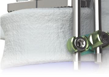
7 Assembling the cranial endplate (optional) The endplate envisaged for the cranial end is inserted into the Assembling Aid (marked CRANIAL). The preassembled implant base unit is attached to the cranial endplate with the end marked CRANIAL in the same position as the previously assembled caudal endplate. This endplate is then also screwed from below using the plate holding screw. The Plate Screw is tightened by hand using the LP Setscrew Driver with Handle. Caution: Ensure that both endplates are assembled with the same angularity. This can be checked using the marking on the Assembling Aid. Inserting the expansion shaft After the implant base unit has been secured, the expansion shaft (Samson Expander) can then be guided into the channel of the inserter on the lefthand side (viewed from the rear). Press the button on the insertion instrument to move the expansion shaft into the final position on the insertion instrument. The torx geometry of the expansion shaft must be connected to the torx of the drive mechanism. Note: The expansion shaft is secured against accidental loss by the mechanics of the button device located on the insertion instrument. Insertion of the implant The preassembled implant secured on the insertion instrument is inserted and the implant position is checked using x-rays. It is important to ensure that the endplates lie as flat as possible against the vertebral body endplates. 7


 is inserted into the torque wrench (Torque Driver - 2,3).")

8 Surgical Technique Expansion of the implant The implant can be expanded by turning the expansion shaft (Samson Expander) on the insertion instrument clockwise. 7 turns on the expansion shaft correspond to a height change at the implant of 1mm. The implant can be retracted again by turning the expansion shaft anti-clockwise. Caution: The implant must be implanted under prestress in order to avoid dislocation. Expansion of the implant must be performed under continuous x-ray control in order to avoid over-distraction or damage of the endplates. The implant has a fixed mechanical stop that limits the maximum expansion way of the implant. If this clearly noticeable stop is reached during the expansion, it may not be further expanded, as this may lead to excessive stress of individual components of the expansion mechanism. Locking of the expansion mechanism Once the implant is expanded, the mechanism has to be locked. For this purpose, the locking screwdriver (Samson Locking Screw Driver T10) is inserted into the torque wrench (Torque Driver - 2,3). The assembled instruments are then guided over the insertion instrument into the torx of the locking screw. Tighten the locking screw clockwise until the torque wrench releases. Removal of the locking screwdriver after the final fixing of the locking screw. Note: The full torque of 2.3Nm is reached when you hear a clicking sound in the torque wrench. Loosening the insertion instrument If the implant is expanded to its final position, the screw connection with the implant can be loosened by turning the holder shaft (Samson Inserter Holder) on the insertion instrument anticlockwise and the insertion instrument can be removed. If it is difficult to loosen the holder shaft, the LP Setscrew Driver with Handle can be used. 8


9 System Subsequent placement of the insertion instrument The insertion instrument can be relocated on the implant for possible position corrections. To do this, the expansion shaft must be removed from the insertion instrument. The exact alignment of the insertion instrument to the implant must be observed. The lugs at the insertion instrument must engage in the provided notches for on the implant base unit. The holder shaft has to be tightened without any resistance. If the fixation of the implant is difficult or if the connection to the instrument is not correct, the insertion instrument must be attached to the implant again. To check the correct attachment it can be pulled at the instrument. A positional correction by a blow of hammer may only be carried out with a completely fixed shaft, in order to avoid possible damage to the implant or instrument. Final construction Finally, the Samson vertebral body replacement is placed in the corpectomy gap. An additional dorsal fixation (e.g. with the VENUS screw and rod system) including transverse connector elements and additional ventral treatment (e.g. with the VENUSnano screw and rod system) is recommended. SAMSON - expansion mechanism The expansion mechanism used by the Samson vertebral body replacement is based on a worm drive. This offers the following advantages: Stepless, extremely fine height adjustment possible No undesirable turning back of the expansion mechanism No springing back of the expansion mechanism and thus no loss of height Extremely low force needed for expansion Fully reversible 9
.")
10 Functional test before use System To guarantee the function of the implant, a short functional test must be performed. First the locking screw located in the implant should be loosened with the Samson Locking Screw Driver T10 by turning it counterclockwise maximal 1,5 turns (minimal 0,5 turns). Then the insertion instrument (Samson Inserter), as described in the surgical steps, is fitted to the implant body and fixed with the holder shaft (Samson Inserter Holder). The expansion shaft (Samson Expander) is then, as described, inserted into the insertion instrument until it engages with the torx geometry of the gear mechanism on the implant base unit (marked in red). The implant is expanded by rotating the expansion shaft in a clockwise direction. Once function is ensured, the implant is turned back to the start by turning the expansion shaft anti-clockwise. The insertion instrument can then be completely removed. 10


11 Access direction for SAMSON Thanks to the flexible connection geometry between implant base unit and endplate, all common access directions can be covered using the Samson vertebral body replacement. The endplates can be attached individually to the implant base unit every 15. The assembly aid included in the set can be used to ensure that the desired assembling position of the endplates is achieved. ventrolateral left ventral ventrolateral right The slim construction of the base unit ensures that it does not protrude over the endplates or only protrudes slightly in selected assembly positions. lateral left lateral right dorsolateral left dorsolateral right The endplate is connected to the base unit via a multi-profile form, which is identical for the cranial and caudal endplates. This rotation-proof connection is secured using a threaded connection between the Plate Screw and the implant base unit. The primary fixation is ensured due to the pyramid-shaped toothing on the endplates. Blasting of the endplate surface using blasting media such as ceramic and aluminium oxide produces a surface structure which promotes optimum osseointegration. 11


12 System Determining the implant height The size information on the preassembled base units (VBR Size 1 to VBR Size 6) indicates the total height of the implant when compressed or expanded to its maximum, including two assembled endplates with an angulation of 0. The total height of the implant is measured without the toothing, i.e. from tooth base to tooth base. If endplates with angulation are used, the heights listed in the table below must also be added to the size information for the preassembled base unit (individually for each respective endplate). The additional height information for the individual endplate types relates to the height with or without toothing as required. Here, the height is determined at the highest point of the relevant implant. To allow subsequent expansion of the implant, the height of the entire structure (base unit with endplates) when compressed must be lower than the defect. Height Dimensions of the base units with endplates VBR Size 1 VBR Size 2 VBR Size 3 VBR Size 4 VBR Size 5 VBR Size 6 Compressed 20 mm 23 mm 27 mm 35 mm 47 mm 71 mm Max. expansion 26 mm 30 mm 38 mm 50 mm 74 mm 120 mm The size overview table is also provided on the implant tray. Calculation example: A required total angulation of 12 has been determined for the endplates. The lower endplate has an angulation of 8 and the upper endplate 4. If a vertebral body replacement VBR Size 2 is used, which is expanded to its maximum, this will produce a maximum implant height from tooth tip to tooth tip of 37.2 mm. The height from tooth base to tooth base is 34.2 mm. Height information VBR Size 1 to 6 Including toothing: 4 endplate + 8 endplate + VBR Size 2 (max. expansion) = 2.9 mm mm + 30 mm = 37.2 mm Endplate angulation Additional height per endplate Including toothing Excluding toothing Excluding toothing: 4 endplate + 8 endplate + VBR Size 2 (max. expansion) = 1.4 mm mm + 30 mm = 34.2 mm 37.2 mm 34.2 mm mm 0 mm +/ mm 1.4 mm +/ mm 2.8 mm 12

13 Plate combination with resulting implant heights Type State 0 /0 0 /4 = 4 /0 VBR Size 1 (20-26) VBR Size 2 (23-30) VBR Size 3 (27-38) VBR Size 4 (35-50) VBR Size 5 (47-74) VBR Size 6 (71-120) Compressed Max. expansion Compressed Max. expansion Compressed Max. expansion Compressed Max. expansion Compressed Max. expansion Compressed Max. expansion 0 /8 = 8 /0 4 /4 4 /8 = 8 /4 Including toothing 23mm 24.4 mm 25.8 mm 25.8 mm 27.2 mm 28.6 mm Excluding toothing 20mm 21.4 mm 22.8 mm 22.8 mm 24.2 mm 25.6 mm Including toothing 29mm 30.4 mm 31.8 mm 31.8 mm 33.2 mm 34.6 mm Excluding toothing 26mm 27.4 mm 28.8 mm 28.8 mm 30.2 mm 31.6 mm Including toothing 26mm 27.4 mm 28.8 mm 28.8 mm 30.2 mm 31.6 mm Excluding toothing 23mm 24.4 mm 25.8 mm 25.8 mm 27.2 mm 28.6 mm Including toothing 33mm 34.4 mm 35.8 mm 35.8 mm 37.2 mm 38.6 mm Excluding toothing 30mm 31.4 mm 32.8 mm 32.8 mm 34.2 mm 35.6 mm Including toothing 30mm 31.4 mm 32.8 mm 32.8 mm 34.2 mm 35.6 mm Excluding toothing 27mm 28.4 mm 29.8 mm 29.8 mm 31.2 mm 32.6 mm Including toothing 41mm 42.4 mm 43.8 mm 43.8 mm 45.2 mm 46.6 mm Excluding toothing 38mm 39.4 mm 40.8 mm 40.8 mm 42.2 mm 43.6 mm Including toothing 38mm 39.4 mm 40.8 mm 40.8 mm 42.2 mm 43.6 mm Excluding toothing 35mm 36.4 mm 37.8 mm 37.8 mm 39.2 mm 40.6 mm Including toothing 53mm 54.4 mm 55.8 mm 55.8 mm 57.2 mm 58.6 mm Excluding toothing 50mm 51.4 mm 52.8 mm 52.8 mm 54.2 mm 55.6 mm Including toothing 50mm 51.4 mm 52.8 mm 52.8 mm 54.2 mm 55.6 mm Excluding toothing 47mm 48.4 mm 49.8 mm 49.8 mm 51.2 mm 52.6 mm Including toothing 77mm 78.4 mm 79.8 mm 79.8 mm 81.2 mm 82.6 mm Excluding toothing 74mm 75.4 mm 76.8 mm 76.8 mm 79.2 mm 79.6 mm Including toothing 74mm 75.4 mm 76.8 mm 76.8 mm 78.2 mm 79.6 mm Excluding toothing 71mm 72.4 mm 73.8 mm 73.8 mm 75.2 mm 76.6 mm Including toothing 123mm mm mm mm mm mm Excluding toothing 120mm mm mm mm mm mm 8 /8 Associated trial Height of associated trial Samson Trial Size 1 Samson Trial Size 2 Samson Trial Size 3 Samson Trial Size 4 Samson Trial Size 5 Samson Trial Size 6 Samson Trial Size Max 23mm 26mm 30mm 38mm 50mm 74mm 123mm Rule for determining the necessary base unit height: 1. Trial has clearance in the prepared implant seat: -> the base unit to be selected corresponds to the size of the trial 2. Trial fits press-fit in the prepared implant seat: -> the base unit to be selected should be one size smaller than the selected trial 3. base unit does not fit in the prepared implant seat: -> the body to be selected should be at least one size smaller than the selected trial, re-check with a smaller trial 13


 is the largest implant when expanded to its maximum expanded state. The individual implant sizes overlap each other as the size increases.")
14 Use of trial implants Implants The size information on the preassembled base units (VBR Size 1 to VBR Size 6) indicates the total height of the implant when compressed or expanded to its maximum, including two assembled endplates with an angulation of 0. The total height of the implant is measured without the toothing, i.e. from tooth base to tooth base. The associated trial implants (Samson Trials) used to determine the required implant height each represent the height of the preassembled base unit in the fully compressed state, including the height of two assembled endplates with an angulation of 0 including toothing. If angled endplates are used, a certain height supplement must be factored in according to the lists on the previous pages. The largest trial (Samson Trial Max) is the largest implant when expanded to its maximum expanded state. The individual implant sizes overlap each other as the size increases. Thus the implant which can best fill the defect should be selected optional 49 Ø20 Ø20 optional 14
15 SAMSON Trial Implants Item no. Description Samson Trial Size Samson Trial Size 2 Trial implants Base units Samson Trial Size Samson Trial Size Samson Trial Size 5 optional Samson Trial Size Samson Trial Size Max Samson Plate Trial 25x Samson Plate Trial 30x20 optional optional Trial Implants Plates Samson Plate Trial 40x Samson Plate Trial 45x Samson Plate Trial 55x20 15
 20 mm 26 mm 2000012330 VBR Size 2 (23-30 mm) 23 mm 30 mm 2000012738 VBR Size 3 (27-38 mm) 27 mm 38 mm 20 mm 2000013550 VBR Size 4 (35-50 mm) 35 mm 50 mm")
16 SAMSON Base Units Implants Item no. Name Diameter Height when compressed Height at max. expansion VBR Size 1 (20-26 mm) 20 mm 26 mm VBR Size 2 (23-30 mm) 23 mm 30 mm VBR Size 3 (27-38 mm) 27 mm 38 mm 20 mm VBR Size 4 (35-50 mm) 35 mm 50 mm VBR Size 5 (47-74 mm) 47 mm 74 mm VBR Size 6 ( mm) optional 71 mm 120 mm Note: The preassembled base units are supplied in the fully compressed position, to prevent the unintentional loosening of individual components. After washing and reprocessing, the base units should also be stored in the implant tray in the compressed position. Base units optional 16

17 SAMSON Plates Item no. Name Length Width Angle Plate 25x20 mm 0 25 mm Plate 30x20 mm 0 30 mm 0 Endplates Plate 40x20 mm 0 20 mm 40 mm Plate 45x20 mm 0 45 mm Plate 55x20 mm 0 55 mm Plate 25x20 mm 4 25 mm Plate 30x20 mm 4 30 mm Plate 40x20 mm 4 20 mm 40 mm Plate 45x20 mm 4 45 mm Plate 55x20 mm 4 55 mm Plate 25x20 mm 8 25 mm Plate 30x20 mm 8 30 mm Plate 40x20 mm 8 20 mm 40 mm Plate 45x20 mm 8 45 mm Plate 55x20 mm 8 55 mm Plate screw 8 Screw 17
18 SAMSON Instruments Instruments Item no. Description SAMSON Inserter SAMSON Inserter Holder Samson Locking Screw Driver T SAMSON Expander SAMSON Inserter Handle PLIF Inserter 18


19 Item no B Description ALIF/PLIF-Inserter B LP Setscrew Driver with Handle Torque Driver 2.3 optional 19
 7157/5246-71 Fax: +49 (0) 7157/5246-66 sales@humantech-solutions.de www.humantech-solutions.de İkitelli OSB Tümsan 2.")
20 Manufacturer and Sales for Europe Marketing Middle East Sales for Latin America Other countries HumanTech Germany GmbH HumanTech Med. Sag. Tic. Ltd. HumanTech Mexico, S. DE R.L. DE C.V. HumanTech Germany GmbH Gewerbestr. 5 D Steinenbronn Germany Phone: +49 (0) 7157/ Fax: +49 (0) 7157/ sales@humantech-solutions.de İkitelli OSB Tümsan 2. Kısım C-Blok No: 47 TR Başakşehir İstanbul Turkey Phone: +90 (0) 212/ Fax: +90 (0) 212/ info@humantech.com.tr Rio Mixcoac No Acacias del Valle Del. Benito Juárez C.P Mexico, D.F. Mexico Phone: +52 (0) 55/ Fax: +52 (0) 55/ info@humantech-solutions.mx Gewerbestr. 5 D Steinenbronn Germany Phone: +49 (0) 7157/ Fax: +49 (0) 7157/ sales@humantech-solutions.de Edition 1/ Subject to change
VENUS Hooks. Hook System
 VENUS Hooks Hook System System VENUS Hooks complements the innovative design features of the standard screws perfectly. They allow the correction and stabilization of the spine for particularly complex
TRISTAN fl e x. Cervical Interbody Fusion
 TRISTAN fl e x Cervical Interbody Fusion System TRISTAN flex is an intelligent and, due to its associated instruments, highly rational cervical interbody device system. TRISTAN flex is an extension of
VENUS SCOLIOSIS. Scoliosis System
 VENUS SCOLIOSIS Scoliosis System System The VENUS Scoliosis System was specially designed for the correction and stabilisation of the spine in particularly complicated anatomies. The system complements
TSLP Thoracolumbar Spine Locking Plate
 Anterior thoracolumbar spine locking plate TSLP Thoracolumbar Spine Locking Plate Surgical Technique Image intensifier control This description alone does not provide sufficient background for direct use
HumanTech. Medical Devices ADONIS. Transforaminal lumbar interbody fusion TLIF
 HumanTech Medical Devices ADONIS Transforaminal lumbar interbody fusion TLIF System The TLIF technique is based on creating unilateral access to the intervertebral disc space by entering via an intervertebral
XRL A modular expandable radiolucent vertebral body replacement system
 XRL A modular expandable radiolucent vertebral body replacement system This publication is not intended for distribution in the USA. SURGICAL TECHNIQUE Table of Contents Introduction XRL 2 AO Spine Principles
VLIFT System Overview. Vertebral Body Replacement System
 VLIFT System Overview Vertebral Body Replacement System VLIFT System System Description The VLIFT Vertebral Body Replacement System consists of a Distractible In Situ (DIS) implant, which enables the surgeon
GIZA Surgical Technique
 GIZA Surgical Technique Vertebral Body Replacement System Manufactured by Titanium alloy material provides mechanical integrity during insertion and distraction, x-ray visibility, and biocompatibility*
SYNEX The vertebral body replacement with ratchet mechanism
 SYNEX The vertebral body replacement with ratchet mechanism Instruments and implants approved by the AO Foundation. This publication is not intended for distribution in the USA. SURGICAL TECHNIQUE Image
ECD EXPANDABLE CORPECTOMY DEVICE Continuously Expandable Vertebral Body Replacement for Tumour Cases
 ECD EXPANDABLE CORPECTOMY DEVICE Continuously Expandable Vertebral Body Replacement for Tumour Cases Instruments and implants approved by the AO Foundation. This publication is not intended for distribution
Synex System TECHNIQUE GUIDE. An expandable vertebral body replacement device
 Synex System TECHNIQUE GUIDE An expandable vertebral body replacement device Original Instruments and Implants of the Association for the Study of Internal Fixation AO ASIF Synex System Overview The Synex
operative technique Universal Application
 operative technique Universal Application Introduction Introduction Building upon the design rationale of the Xia Spinal System, the new Xia Spinal System represents the latest advancement in spinal implant
Replacement Device A modular expandable radiolucent vertebral body replacement system
 XRL Vertebral Body Replacement Device A modular expandable radiolucent vertebral body replacement system SURGICAL TECHNIQUE TABLE OF CONTENTS Introduction XRL System 2 AO Principles 5 Indications and Contraindications
The Implant. (Klappen außen sind nur 192 mm breit!) Ordering information. You start we help with our clearly arranged Starter Kit:
 Ordering information. You start we help with our clearly arranged Starter Kit:") ATHLET PRODUCT INFORMATION The Implant 1 construct = 1 main body + 1 end body (Klappen außen sind nur 192 mm breit!) Latch mechanism for secure connection of the implant components Ordering information
ATHLET PRODUCT INFORMATION The Implant 1 construct = 1 main body + 1 end body (Klappen außen sind nur 192 mm breit!) Latch mechanism for secure connection of the implant components Ordering information
EXCELLA ll. Spinal System
 EXCELLA ll Spinal System Excella II Spinal System INDICATIONS FOR USE The Innovasis Excella II Spinal System is intended for use in the non-cervical area of the spine. WARNING: The safety and effectiveness
LUMBAR POSTERIOR MINIMALLY INVASIVE SYSTEM. Surgical Technique
 LUMBAR POSTERIOR MINIMALLY INVASIVE SYSTEM Surgical Technique Joint Spine Sports Med M.U.S.T. Mini Open Surgical Technique Joint Spine Sports Med CAUTION Federal law (USA) restricts this device to sale
M.I.S. MAKE IT SMART IN ONE SYSTEM. Surgical Technique. Hip Knee Spine Navigation
 M.I.S. MAKE IT SMART IN ONE SYSTEM Surgical Technique Hip Knee Spine Navigation M.U.S.T. Mini Open Surgical Technique Hip Knee Spine Navigation 2 C O N T E N T S 1 INTRODUCTION 4 2 SURGICAL TECHNIQUE 5
Thoracolumbar Anterior Compression (TAC) System. Allows distraction, compression, and lateral fixation of the lower thoracic and lumbar spine.
 System. Allows distraction, compression, and lateral fixation of the lower thoracic and lumbar spine.") Thoracolumbar Anterior Compression (TAC) System. Allows distraction, compression, and lateral fixation of the lower thoracic and lumbar spine. Technique Guide Instruments and implants approved by the AO
Thoracolumbar Anterior Compression (TAC) System. Allows distraction, compression, and lateral fixation of the lower thoracic and lumbar spine. Technique Guide Instruments and implants approved by the AO
USS Variable Axis Screw (VAS) System. For posterior fixation of the lumbar spine.
 System. For posterior fixation of the lumbar spine.") USS Variable Axis Screw (VAS) System. For posterior fixation of the lumbar spine. Technique Guide Instruments and implants approved by the AO Foundation Table of Contents Introduction USS Variable Axis
USS Variable Axis Screw (VAS) System. For posterior fixation of the lumbar spine. Technique Guide Instruments and implants approved by the AO Foundation Table of Contents Introduction USS Variable Axis
Valencia Pedicle Screw Surgical Technique
 Valencia Pedicle Screw Surgical Technique VALENCIA CIRCUIT TABLE OF CONTENTS Design Rationale Indications for Use Surgical Technique 1. Pedicle Preparation 2. Screw Insertion 3. Rod Placement 4. Locking
Technique Guide. ECD Expandable Corpectomy Device. Continuously Expandable Vertebral Body Replacement for Tumour Cases.
 Technique Guide ECD Expandable Corpectomy Device. Continuously Expandable Vertebral Body Replacement for Tumour Cases. Table of Contents Introduction Overview 2 AO ASIF Principles 4 Indications and Contraindications
Cervical Solutions. Optio-C Anterior Cervical Plate. with Allograft/Autograft. Surgical Technique Guide
 Cervical Solutions Optio-C Anterior Cervical Plate with Allograft/Autograft Surgical Technique Guide 2 Optio-C Anterior Cervical Plate with Allograft/Autograft Surgical Technique Guide The Optio-C System
Imola Lateral IBF System Surgical Technique
 Imola Lateral IBF System Surgical Technique IMOLA CIRCUIT TABLE OF CONTENTS Design Rationale Instructions for Use Surgical Technique 1. Table Mounting 2. Surgical Planning & Targeting 3. Access and Preparation
Surgical technique. synex. The vertebral body replacement with ratchet mechanism.
 Surgical technique synex. The vertebral body replacement with ratchet mechanism. Table of contents Indications and contraindications 2 Implants 3 Surgical technique 4 Cleaning of instruments 10 Optional
Ref: Q400-09T1 EBI Spine. September 05/VS02. c/o BIOMET Spain Orthopaedics, S.L.
 Ref: Q400-09T1 EBI Spine. September 05/VS02 c/o BIOMET Spain Orthopaedics, S.L. www.ebimedical.com EBI Omega 21 TM LP Since its introduction in 1996, and with thousands of patients treated so far, the
L-VARLOCK. Posterior Lumbar Cage with adjustable lordosis. S urgical T echnique
 L-VARLOCK Posterior Lumbar Cage with adjustable lordosis S urgical T echnique Introduction Designed and manufactured by KISCO International, L-VARLOCK cages are made of titanium alloy Ti 6AI 4V (standards
The vertebral body replacement with ratchet mechanism. Synex. Surgical Technique
 The vertebral body replacement with ratchet mechanism Synex Surgical Technique Image intensifier control This description alone does not provide sufficient background for direct use of DePuy Synthes products.
VERTEX SELECT. surgical technique. adjustability. Flexibility. adaptability. Reconstruction System
 VERTEX SELECT Reconstruction System surgical technique adjustability. Flexibility. adaptability. adjustability. Flexibility. adaptability. The VERTEX SELECT Reconstruction System is a comprehensive set
Technique Guide. ArcoFix. Anterior-only reduction plate.
 Technique Guide ArcoFix. Anterior-only reduction plate. Table of Contents Introduction ArcoFix 2 AO Principles 4 Indications and Contraindications 5 Surgical Technique Preoperative Planning 6 Insert ArcoFix
USS Variable Axis Screw
 USS Variable Axis Screw Polyaxial side-opening pedicle screw Surgical technique Original Instruments and Implants of the Association for the Study of Internal Fixation AO/ASIF USS Variable Axis Screw
Collinear Reduction Clamp
 For minimally invasive fracture reduction Collinear Reduction Clamp Surgical Technique Image intensifier control This description alone does not provide sufficient background for direct use of DePuy Synthes
X-spine Surgical Technique
 X-spine Surgical Technique The X90 Pedicle Screw System Revolutionary Design and Function This document is intended exclusively for experts in the field, particularly physicians, and is not intended for
Thoracolumbar Spine Locking Plate (TSLP) System. A low-profile plating system for anterior stabilization of the thoracic and lumbar spine.
 System. A low-profile plating system for anterior stabilization of the thoracic and lumbar spine.") Thoracolumbar Spine Locking Plate (TSLP) System. A low-profile plating system for anterior stabilization of the thoracic and lumbar spine. Technique Guide Instruments and implants approved by the AO Foundation
Thoracolumbar Spine Locking Plate (TSLP) System. A low-profile plating system for anterior stabilization of the thoracic and lumbar spine. Technique Guide Instruments and implants approved by the AO Foundation
Zero-P Instruments and Implants. Zero-profile anterior cervical interbody fusion (ACIF) device.
 device.") Zero-P Instruments and Implants. Zero-profile anterior cervical interbody fusion (ACIF) device. Technique Guide Instruments and implants approved by the AO Foundation Table of Contents Introduction Zero-P
Zero-P Instruments and Implants. Zero-profile anterior cervical interbody fusion (ACIF) device. Technique Guide Instruments and implants approved by the AO Foundation Table of Contents Introduction Zero-P
TELESCOPIC CORPECTOMY SYSTEM
 TELESCOPIC CORPECTOMY SYSTEM The simplified Vertebral Body Replacement Features of Thoraco-Lumbar TeCorp Modular endplates 3 colour coded endplates permit 9 possible angular combinations Safe support and
TELEFIX SURGICAL TECHNIQUE. Implant system for the anterior stabilization of the thoracolumbar spine
 TELEFIX Implant system for the anterior stabilization of the thoracolumbar spine Instruments and implants approved by the AO Foundation. This publication is not intended for distribution in the USA. SURGICAL
The Most Reliable Spinal Solution
 MFG : 09.02.20 REV : 1 4CIS VANE introduces you the reliable pedicle screw The Most Reliable Spinal Solution Non-slip threaded joint Ergonomic design Wedged trapezoid thread Superior locking mechanism
Mini External Fixator.
 Mini External Fixator. Assembly and Surgical Technique This publication is not intended for distribution in the USA. Instruments and implants approved by the AO Foundation. Image intensifier control Warning
VECTRA-T SURGICAL TECHNIQUE. The Translational Anterior Cervical Palate System. This publication is not intended for distribution in the USA.
 VECTRA-T The Translational Anterior Cervical Palate System This publication is not intended for distribution in the USA. SURGICAL TECHNIQUE Image intensifier control This description alone does not provide
ACP. Anterior Cervical Plate System SURGICAL TECHNIQUE
 ACP Anterior Cervical Plate System SURGICAL TECHNIQUE ACP TABLE OF CONTENTS INTRODUCTION 4 INDICATIONS AND CONTRAINDICATIONS 5 WARNINGS AND PRECAUTIONS 6 IMPLANT DESCRIPTION 7 INSTRUMENTS 10 SURGICAL
PACH PLATE 2 OR 4 HOLE FIXATION
 2 OR 4 HOLE FIXATION The Science of Fusion PACH_v6.indd 1 6/03/2015 7:10 am PACH Plate Design Rationale The PACH Plate has been designed to be used as an anterior or lateral fixation plate for the thoracolumbar,
The Versatile Polyaxial Solution for the Universal Spine Systems. USS II Polyaxial. Surgical Technique
 The Versatile Polyaxial Solution for the Universal Spine Systems USS II Polyaxial Surgical Technique Image intensifier control This description alone does not provide sufficient background for direct use
Dymaxeon Spine System. Simple, Streamlined, Smart. Surgical Procedure
 Simple, Streamlined, Smart Surgical Procedure Introduction The Dymaxeon pedicle screw system offers the spinal surgeon an outstanding system for stabilization of spinal deformity, reduction of spondylolisthesis,
In-Space. Interspinous distraction through a mini-open, posterior, unilateral approach.
 In-Space. Interspinous distraction through a mini-open, posterior, unilateral approach. Surgical Technique Posterior Approach PRODUCT OBSOLETED 30th September 2017 DSEM/SPN/0915/0348(1) This publication
FACET WEDGE. Facet joint fixation device.
 FACET WEDGE. Facet joint fixation device. Technique Guide Synthes FACET WEDGE Technique Guide /44 Synthes FACET WEDGE Technique Guide /44 Table of Contents Introduction FACET WEDGE 3 AO Principles 4 Indications
Interbody fusion cage for the transforaminal approach. Travios. Surgical Technique
 Interbody fusion cage for the transforaminal approach Travios Surgical Technique Image intensifier control This description alone does not provide sufficient background for direct use of DePuy Synthes
4.5 System. Surgical Technique. This publication is not intended for distribution in the USA.
 4.5 System Surgical Technique This publication is not intended for distribution in the USA. Contents EXPEDIUM 4.5 Spine System 2 Features and Benefits 3 Surgical Technique Extended Tandem Connector 4 Placement
Solitaire Anterior Spinal System
 Surgical Technique Solitaire Anterior Spinal System Independent Stabilization for the Anterior Column Available in Titanium and Contents Introduction... Page 1 Design Features... Page 2 Instruments...
nva Anterior Lumbar Interbody Fusion System
 nva Anterior Lumbar Interbody Fusion System 1 IMPORTANT INFORMATION FOR PHYSICIANS, SURGEONS, AND/OR STAFF The nv a, nv p, and nv t are an intervertebral body fusion device used in the lumbar spine following
ARIA. Expandable PLIF Cage System. Implants - Instruments Surgical Technique
 ARIA Expandable PLIF Cage System Implants - Instruments Surgical Technique Introduction The anatomical design and aggressive tooth pattern prevents migration of the implant. Aria offers a very firm grip
ADONIS POSTERIOR LUMBAR INTERBODY FUSION PLIF
 ADONIS POSTERIOR LUMBAR INTERBODY FUSION PLIF System ADONIS -PLIF cages are indicated for anterior lumbar vertebral body fusion. The implants are designed to be perfectly adapted to the anatomy of vertebral
Y o u r Id e a s En g i n e e r e d t o Li f e
 ISSYS LP Spinal Fixation System Surgical Guide Y o u r Id e a s En g i n e e r e d t o Li f e In t r o d u c t i o n ISSYS LP Sp i n a l Fixation System The foundation of the ISSYS LP Spinal Fixation System
A U X I L I A R Y C O N N E C T O R S Surgical Technique
 A U X I L I A R Y C O N N E C T O R S Surgical Technique AUXILIARY CONNECTORS ISSYS LP Auxiliary Connectors The ISSYS LP auxiliary connectors were designed to provide medial-lateral variability for the
Surgical Technique. Occipito-Cervico-Thoracic System
 OASYS Surgical Technique Occipito-Cervico-Thoracic System System Overview The OASYS Occipito-Cervico-Thoracic System was developed to provide the surgeon with versatility for the treatment of pathologies
EFSPINE CERVICAL COMBINED SET DISC PROTHESIS ORGANIZER BOX
 EFSPINE CERVICAL COMBINED SET INSTRUMENTS CERVICAL CAGE & DISC PROTHESIS ORGANIZER BOX Cervical Thoracic Thoraco - Lumbar Sacral EFSPINE CERVICAL COMBINED SET CERVICAL IMPLANTS INTRODUCTION Cervical Disc
SynCage-C short. Surgical Technique. This publication is not intended for distribution in the USA.
 SynCage-C short Surgical Technique This publication is not intended for distribution in the USA. Instruments and implants approved by the AO Foundation. Table of contents Implants 2 Indications/contra-indications
Technique Guide. Midface Distractor System. For the temporary stabilization and gradual lengthening of the cranial or midfacial bones.
 Technique Guide Midface Distractor System. For the temporary stabilization and gradual lengthening of the cranial or midfacial bones. Table of Contents Introduction Midface Distractor System 2 Indications
LCP Medial Distal Tibia Plate, without Tab. The Low Profile Anatomic Fixation System with Angular Stability and Optimal Screw Orientation.
 LCP Medial Distal Tibia Plate, without Tab. The Low Profile Anatomic Fixation System with Angular Stability and Optimal Screw Orientation. Technique Guide LCP Small Fragment System Table of Contents Introduction
mambo modular cervical plate system
 mambo modular cervical plate system mambo modular cervical plate system Overview of system & implant components Philosophy of dynamic instrumentation Indications & Surgical technique Tray design Seite
MATRIX Spine System Deformity
 A Solution for Simple and Complex Spine Pathology MATRIX Spine System Deformity Surgical Technique Image intensifier control This description alone does not provide sufficient background for direct use
Technique Guide. Universal Spinal System (USS). Designed to achieve the goals of scoliosis surgery.
. Designed to achieve the goals of scoliosis surgery.") Technique Guide Universal Spinal System (USS). Designed to achieve the goals of scoliosis surgery. Table of Contents Introduction Universal Spinal System 2 AO ASIF Principles of Internal Fixation 3 Indications
Technique Guide Universal Spinal System (USS). Designed to achieve the goals of scoliosis surgery. Table of Contents Introduction Universal Spinal System 2 AO ASIF Principles of Internal Fixation 3 Indications
InCoreTM Lapidus System
 InCoreTM Lapidus System Precision Guided Correction Surgical Technique InCore TM Lapidus System Precision Guided Correction Tri-Planar Correction Targeting Guide is intended to aid and stabilize angular/rotational
Humerus Block. Discontinued December 2016 DSEM/TRM/0115/0296(1) Surgical Technique. This publication is not intended for distribution in the USA.
 Surgical Technique. This publication is not intended for distribution in the USA.") Humerus Block Surgical Technique Discontinued December 2016 DSEM/TRM/0115/0296(1) This publication is not intended for distribution in the USA. Instruments and implants approved by the AO Foundation. Contents
Humerus Block Surgical Technique Discontinued December 2016 DSEM/TRM/0115/0296(1) This publication is not intended for distribution in the USA. Instruments and implants approved by the AO Foundation. Contents
nvp Posterior Lumbar Interbody Fusion System
 nvp Posterior Lumbar Interbody Fusion System 1 IMPORTANT INFORMATION FOR PHYSICIANS, SURGEONS, AND/OR STAFF The nv a, nv p, and nv t are an intervertebral body fusion device used in the lumbar spine following
Handling instructions. USS Low Profile. Thoracolumbar posterior fixation system.
 Handling instructions USS Low Profile. Thoracolumbar posterior fixation system. U Table of contents Introduction Indications and contraindications 3 USS Low Profile implants 4 Handling implants with stick
nvt Transforaminal Lumbar Interbody Fusion System
 nvt Transforaminal Lumbar Interbody Fusion System 1 IMPORTANT INFORMATION FOR PHYSICIANS, SURGEONS, AND/OR STAFF The nv a, nv p, and nv t are an intervertebral body fusion device used in the lumbar spine
SpineJack. Ø 5.8 mm Ø 5.0 mm Ø 4.2 mm. Controlled Anatomical Restoration
 SpineJack Ø 5.8 mm Ø 5.0 mm Ø 4.2 mm Controlled Anatomical Restoration Introducing Controlled the Anatomical Surgical Restoration Technique SpineJack The SpineJack System is designed for the Anatomical
EXACTECH SPINE. Operative Technique. Cervical Spacer System. Surgeon focused. Patient driven. TM
 EXACTECH SPINE Operative Technique Cervical Spacer System Surgeon focused. Patient driven. TM ACAPELLA ONE Acapella One Cervical Spacer System is an anterior cervical discectomy and fusion device with
SFX Cross Connector System. Surgical Technique Guide
 SFX Cross Connector System Surgical Technique Guide Introduction The EXPEDIUM SFX Cross Connector System redefines ease-of-use, implant versatility, and construct security with an advanced top-loading
SYNFIX. LR Stand Alone Spacer. Instruments and implants for stand alone anterior lumbar interbody fusion (ALIF). Technique Guide
. Technique Guide") SYNFIX LR Stand Alone Spacer. Instruments and implants for stand alone anterior lumbar interbody fusion (ALIF). Technique Guide Table of Contents Introduction SYNFIX LR Stand Alone Spacer 2 AO Principles
SYNFIX LR Stand Alone Spacer. Instruments and implants for stand alone anterior lumbar interbody fusion (ALIF). Technique Guide Table of Contents Introduction SYNFIX LR Stand Alone Spacer 2 AO Principles
Integra. DigiFuse Cannulated Intramedullary Fusion System SURGICAL TECHNIQUE
 Integra DigiFuse Cannulated Intramedullary Fusion System SURGICAL TECHNIQUE Table of Contents Design Rationale... 2 System Features... 2 Indications... 2 Contraindications... 2 Surgical Technique...3 Step
DISTRACTION PRODUCT OVERVIEW. For a wide variety of facial applications
 DISTRACTION PRODUCT OVERVIEW For a wide variety of facial applications DISTRACTION PRODUCT OVERVIEW. STRONG, MODULAR, VERSATILE CRANIOFACIAL DISTRACTION External Midface Distractor Distraction of the maxilla,
Veyron -C Anterior Cervical System Surgical Technique
 Veyron -C Anterior Cervical System Surgical Technique 2 Veyron-C Anterior Cervical System Surgical Technique Veyron-C Anterior Cervical System Surgical Technique Description, Indications & Contraindications...3
SYNFIX EVOLUTION SECURED SPACER SYSTEM
 SYNFIX EVOLUTION SECURED SPACER SYSTEM Instruments and implants for stand-alone anterior lumbar interbody fusion Instruments and implants approved by the AO Foundation. This publication is not intended
SURGICAL TECHNIQUE. SECURIS Pedicle Screw System for Minimally Invasive Surgery. 2 I SECURIS Pedicle Screw System
 Surgical Technique e Guide SECURIS Pedicle Screw System for Minimally Invasive Surgery Securis Pedicle Screw System has been engineered to provide temporary posterior stabilization of the thoracolumbar
100 Interpace Parkway Parsippany, NJ
 100 Interpace Parkway Parsippany, NJ 07054 www.biometspine.com 800-526-2579 All trademarks are the property of Biomet, Inc. or one of its subsidiaries, unless otherwise indicated. Rx Only. 2009 EBI, LLC.
L8 Spine System SURGICAL TECHNIQUE. Add: No.1-8, Tianshan Road, Xinbei District, Changzhou, Jiangsu, China
 Add: No.-8, Tianshan Road, Xinbei District, Changzhou, Jiangsu, China 23022 Tel: 0086 59 8595556 Fax: 0086 59 859555 Http://www.kanghui.com Add: F25, Shanghai International Pharmaceutical Trad & Exhibition
Mandible External Fixator II. Provides treatment for fractures of the maxillofacial area.
 Mandible External Fixator II. Provides treatment for fractures of the maxillofacial area. Technique Guide This publication is not intended for distribution in the USA. Instruments and implants approved
Threshold Pedicular Fixation System Surgical Technique
 Threshold Pedicular Fixation System Surgical Technique Table of Contents Patient Preparation and Positioning... 2 Determining Incision Location... 3 Assembling the Cannulated Awl... 4 Guide Wire Placement...
Correction System. Surgical Technique
 Nextra Hammertoe Correction System Surgical Technique Maximized Bone Purchase* Stable and Secure Phalanx Optimized Screw Design Adjustable Bone-to-Bone Apposition Progressive Ratchet Tightening Mechanism
SURGICAL TECHNIQUE. Easyspine PEDICLE SCREW SYSTEM
 SURGICAL TECHNIQUE Easyspine PEDICLE SCREW SYSTEM Easyspine PEDICLE SCREW SYSTEM Designed by leading spine surgeons, Easyspine features a simplified surgical technique and adaptable implants to accommodate
HawkeyeTM Peek. surgical technique
 HawkeyeTM Peek surgical technique Introduction The ChoiceSpine HAWKEYE Vertebral Body Replacement (VBR) System is intended for use in the thoracolumbar spine (T1 - L5) to replace a collapsed, damaged,
Technique Guide. 3.5 mm LCP Olecranon Plates. Part of the Synthes locking compression plate (LCP) system.
 system.") Technique Guide 3.5 mm LCP Olecranon Plates. Part of the Synthes locking compression plate (LCP) system. Table of Contents Introduction 3.5 mm LCP Olecranon Plates 2 AO Principles 3 Indications 3 Clinical
Technique Guide 3.5 mm LCP Olecranon Plates. Part of the Synthes locking compression plate (LCP) system. Table of Contents Introduction 3.5 mm LCP Olecranon Plates 2 AO Principles 3 Indications 3 Clinical
Technique Guide. Zero-P VA. Variable angle zero-profile anterior cervical interbody fusion (ACIF) device.
 device.") Technique Guide Zero-P VA. Variable angle zero-profile anterior cervical interbody fusion (ACIF) device. Image intensifier control Warning This description alone does not provide sufficient background
Technique Guide Zero-P VA. Variable angle zero-profile anterior cervical interbody fusion (ACIF) device. Image intensifier control Warning This description alone does not provide sufficient background
Correction System. Surgical Technique
 Nextra Hammertoe Correction System Surgical Technique Maximized Bone Purchase* Stable and Secure Phalanx Optimized Screw Design Adjustable Bone-to-Bone Apposition Progressive Ratchet Tightening Mechanism
SynCage. Surgical Technique. This publication is not intended for distribution in the USA. Instruments and implants approved by the AO Foundation.
 SynCage Surgical Technique This publication is not intended for distribution in the USA. Instruments and implants approved by the AO Foundation. Image intensifier control Warning This description alone
TM TM Surgical Technique
 TM TM Surgical Technique TABLE OF CONTENTS Reli SP Spinous Plating System Overview Device Description Implant Features Indications Instruments Access Instruments Preparation Instruments Insertion Instruments
Surgical Technique. DePuy International Ltd St Anthony s Road Leeds LS11 8DT England Tel: +44 (113) Fax: +44 (113)
 Fax: +44 (113)") Surgical Technique DePuy Spine is a joint venture with Biedermann Motech GmbH. This publication is not intended for distribution in the USA. DePuy Spine, Slim-loc and Cam-loc are all trademarks of DePuy
Surgical Technique DePuy Spine is a joint venture with Biedermann Motech GmbH. This publication is not intended for distribution in the USA. DePuy Spine, Slim-loc and Cam-loc are all trademarks of DePuy
Contact Fusion Cage. Surgical Technique
 Contact Fusion Cage Surgical Technique Image intensifier control This description alone does not provide sufficient background for direct use of DePuy Synthes products. Instruction by a surgeon experienced
TABLE OF CONTENTS. Vault C Anterior Cervical Discectomy 2 and Fusion (ACDF) System Overview. Implants 3. Instruments 5. Surgical Technique 10
 System Overview. Implants 3. Instruments 5. Surgical Technique 10") Surgical Technique TABLE OF CONTENTS Vault C Anterior Cervical Discectomy 2 and Fusion (ACDF) System Overview Indications 2 Implants 3 Instruments 5 Surgical Technique 10 1. Preoperative planning 10 2.
Surgical Technique TABLE OF CONTENTS Vault C Anterior Cervical Discectomy 2 and Fusion (ACDF) System Overview Indications 2 Implants 3 Instruments 5 Surgical Technique 10 1. Preoperative planning 10 2.
ARCH Laminoplasty System
 Dedicated System for Open-door Laminoplasty ARCH Laminoplasty System Surgical Technique Image intensifier control This description alone does not provide sufficient background for direct use of DePuy Synthes
SURGICAL TECHNIQUE GUIDE TRESTLE. Anterior Cervical Plating System
 SURGICAL TECHNIQUE GUIDE TRESTLE Anterior Cervical Plating System 2 SURGICAL TECHNIQUE GUIDE SURGICAL TECHNIQUE GUIDE System Features Large window enables visualization of graft site and end plates Screw
CSS Combined Spine System
 CSS Combined Spine System H- CSS Combined Spine System H- CSS Combined Spinal System : 800000 H-3 CSS Combined Spinal System : 800000 Ref.Number Description Pieces Ref.Number Description Pieces 00000 Open
ONE SYSTEM, MULTIPLE OPTIONS. Surgical Technique. Hip Knee Spine Navigation
 ONE SYSTEM, MULTIPLE OPTIONS Surgical Technique Hip Knee Spine Navigation MUST MINI Surgical Technique Hip Knee Spine Navigation INTRODUCTION The M.U.S.T. Mini posterior cervical screw system is a modular
CSLP-Cervical Spine Locking Plate
 For anterior, cervical fixation CSLP-Cervical Spine Locking Plate Surgical Technique Image intensifier control This description alone does not provide sufficient background for direct use of DePuy Synthes
Handling Technique. Collinear Reduction Clamp. For minimally invasive fracture reduction.
 Handling Technique Collinear Reduction Clamp. For minimally invasive fracture reduction. Table of Contents Collinear Reduction Clamp 2 Handling Technique 4 Ordering Information 10 Warning This description
Lumbar Dynamic. Reinhold Knebel Product Manager
 Lumbar Dynamic Reinhold Knebel Product Manager The DSS system provides options for dynamic and rigid stabilization to treat hypermobile segments and segments that require fusion. Allows pedicle displacement
 Visit our website on www.biotech-medical.com The DLP - Dorso-Lumbar Polyaxial Screw System has been designed to address the pathologies of the thoracolumbar spine. The DLP System contains a wide range
ACIS Anterior Cervical Interbody Spacer
 Implants and Instruments for Interbody Fusion Available in both PEEK and ProTi 360º Titanium Integrated Technology ACIS Anterior Cervical Interbody Spacer Surgical Technique Image intensifier control This
Apache Cervical Interbody Fusion Device. Surgical Technique. Page of 13. LC-005 Rev F
 LC-005 Rev F Apache Cervical Interbody Fusion Device Page of 13 Surgical Technique INDICATIONS: When used as an intervertebral body fusion device, the Genesys Spine Interbody Fusion System is indicated