Sphenoid bone changes in rapid maxillary expansion assessed with cone-beam computed tomography
|
|
|
- Britton Campbell
- 5 years ago
- Views:
Transcription
1 Original Article THE KOREAN JOURNAL of ORTHODONTICS pissn eissn X Sphenoid bone changes in rapid maxillary expansion assessed with cone-beam computed tomography Lucas S. Stepanko Manuel O. Lagravère Faculty of Medicine and Dentistry, University of Alberta, Edmonton, AB, Canada Objective: Rapid maxillary expansion (RME) is used to expand the maxilla and increase arch perimeter; yet, there are few reports on its effects on the sphenoid bone. With cone-beam computed topography (CBCT), it is possible to visualize sphenoid bone changes. The purpose of this study was to investigate sphenoid bone changes observed in conjunction with RME treatments, using CBCT. Methods: Sixty patients (34 women and 26 men, aged years) underwent RME as part of their orthodontic treatment. Patients were randomly assigned to one of three groups: a tooth-anchored group, a bone-anchored group, or a control group. Initial CBCT scans were performed preceding the RME treatment (T 1 ) and again directly after the completion of expansion (T 2 ). Statistical analysis included ANOVA, descriptive statistics, and the intraclass correlation coefficient (ICC). Results: The reliability of the landmark location was at least 0.783, and the largest ICC mean measurement error was 2.32 mm. With regard to distances, the largest change was 0.78 mm, which was not statistically significant (p > 0.05). Statistical significance was established in patient groups of the same sex and treatment type for the following distance measurements: right anterior lateral pterygoid plate to the right edge of the hypophyseal fossa (d 2 ), anterior distance between the medial pterygoid plates (d 4 ), and anterior distance between the left medial and lateral plates (d 8 ). Conclusions: In this study, there were no clinically significant changes in the sphenoid bone due to RME treatments regardless of sex or treatment type. [Korean J Orthod 2016;46(5): ] Key words: Three-dimensional cephalometrics, Expansion, Cone-beam computed tomography, Sphenoid bone Received October 7, 2015; Revised December 30, 2015; Accepted January 27, Corresponding author: Manuel O. Lagravère. Assistant Professor, Faculty of Medicine and Dentistry, Edmonton Clinic Health Academy 5-524, University of Alberta, Edmonton, Alberta T6G 2N8, Canada. Tel manuel@ualberta.ca The authors report no commercial, proprietary, or financial interest in the products or companies described in this article The Korean Association of Orthodontists. This is an Open Access article distributed under the terms of the Creative Commons Attribution Non-Commercial License ( which permits unrestricted non-commercial use, distribution, and reproduction in any medium, provided the original work is properly cited. 269
2 INTRODUCTION Arch width discrepancy is a common orthodontic problem for which the treatment of choice is maxillary expansion. Several different protocols are used for this treatment (rapid, slow, and surgical), as are various different types of appliances (i.e., hyrax, haas, and quadhelix). One of the protocols most commonly used is rapid maxillary expansion (RME), wherein a conventional fixed appliance is cemented onto 2 or 4 posterior teeth, and separation of the suture is accomplished by the turning of an expansion screw. This type of treatment has been used for more than a century and was first reported in 1860 by Emerson Angell. 1 RME separates the palatal suture and reportedly changes the surrounding sutural structures (i.e., nasal suture, the maxillary zygomatic suture, and zygomatic temporal suture). 2 While the purpose of RME is to separate both halves of the maxilla, each bone is connected posteriorly to other bones, which creates resistance to expansion. The sphenoid bone, through the pterygoid plates, is one of these direct attachments. As the conventional appliances used for this treatment are anchored to the teeth, one of the most common side-effects is lateral movement of clinical crowns with concomitant lingual movement of their respective roots. 3 Complete skeletal expansion is not accomplished because of resistance of the adjacent hard and soft structures surrounding the maxillary bones. Among these is the sphenoid bone, which is attached to the maxillary bone through the pterygomaxillary suture at the pterygoid plate level. 2 Given reports of a posterior maxillary sutural width increase of 1.12 mm due to RME, 4 it was hypothesized that the sphenoid bone may also be affected by this orthodontic movement. Of note however, the effects of expansion treatment on the sphenoid bone are not very well understood, as traditional radiographs are two-dimensional (2D) and thus do not enable true visualization of the sphenoid bone itself. Because they are 2D, radiographs depict the superimposition of structures, preventing a clear view of the sphenoid bone. This renders analysis of this specific structure via this imaging modality very difficult. As early as 1982, Timms et al. 5 reported using a computed tomography (CT) scan to analyze the effects of RME. With the use of cone-beam CT (CBCT), most of the limitations of 2D radiography can be overcome, and a more accurate representation of the changes occurring can be obtained. The application of CBCT in dentistry has resulted in accurate three-dimensional (3D) recreations of previously unseen structures. Furthermore, CBCT s accuracy and direct visualization of structures have been clearly demonstrated to increase diagnostic accuracy. 6 It also allows dentists to observe and analyze structures without magnification or distortion and facilitates the segmentation of specific bones for analysis. 7 Currently, there are no CBCT indication criteria; however, this technology may become the standard diagnostic modality in the future. CBCT images have previously been used to investigate the effects of RME on the sphenoid bone. 8 In that study, there was an average opening of 1.88 mm at the maxillary suture and a 0.57-mm increase in the sphenooccipital synchondrosis in patients aged 8 11 years. Although that study shares some similarities with the present study, the sample in the present study consisted of patients aged years, and changes in areas of the sphenoid bones other than the synchondrosis were investigated. Magnusson et al. 9 recently reported a non-uniform transverse expansion with substantially larger expansion posteriorly than anteriorly. It was also noted that significant lateral tipping was only recorded posteriorly. The purpose of the present study was to investigate skeletal changes in the sphenoid bone using 3D CBCT images after RME treatment with a tooth-borne or a bone-borne maxillary expander. Complete analysis of the sphenoid bone was conducted with a focus on the pterygoid plate region to quantify changes occurring because of RME. MATERIALS AND METHODS The present study was approved by the Health Research Ethics Board of the University of Alberta (Pro ). The sample used in this study was obtained from a previous research sample. 3 A total of 60 patients (26 men, 34 women) aged years with maxillary expansion treatment planned were randomly allocated Table 1. Sex and age distribution in each group Treatment Sex Frequency Age (yr) Mean SD Group A (BAME) Male Female Total Group B (TAME) Male Female Total Group C (control) Male Female Total BAME, Bone-anchored maxillary expander; TAME, traditional tooth-anchored maxillary expander; SD, standard deviation. 270


, and an expansion")

 Saggital view (YZ)")


3 Stepanko and Lagravère Sphenoid bone changes in maxillary expansion to three groups during an 18-month recruitment period. Table 1 summarizes the sex and age distribution of the patients in each group. The 20 patients in group A received a traditional tooth-anchored maxillary expander (TAME) (Hyrax with bands on first permanent molars and first premolars). The 20 patients in group B received a bone-anchored maxillary expander (BAME) composed of two custom milled stainless steel onplants (8 mm in diameter and 3 mm in height), two miniscrews (12 mm in length and 1.5 mm in diameter, Straumann GBR-System; Straumann, Andover, MA, USA), and an expansion screw (Palex II Extra-Mini Expander; Table 2. Landmarks defined and shown on three-dimensional (3D) and cross-sectional images Landmark 3D reconstruction Axial view (XY) Saggital view (YZ) Coronal view (XZ) Foramina ovale A broad aperture in the greater wing of the sphenoid located lateral posterior to the foramen lacerum, and anterior to the foramen spinosum. Foramina spinosum A smaller aperture at the base of the skull anterior to the spine of the sphenoid and posterior lateral to the foramen ovale. Hypophysial fossa A semi tubular depression located medial between the middle cranial fossae. The landmarks were set on the lateral edges of the saddle-like depression, slightly below the floor of the depression. Foramina lacerum Aperture at the base of the skull surrounded by the sphenoid, petrous portion of the temporal bone, and basioccipital. Located lateral and inferior to the hypophysial fossa. 271

 Saggital view (YZ) Coronal view")


4 Stepanko and Lagravère Sphenoid bone changes in maxillary expansion Table 2. Continued Landmark 3D reconstruction Axial view (XY) Saggital view (YZ) Coronal view (XZ) Medial pterygoid A thin plate beginning at the pterygoid process, with the landmark located at the anterior corner of the plate anterior pterygoid fossa and the medial plate, in the slice showing the longest, most well defined image of the plates. Medial pterygoid A thin plate beginning at the pterygoid process, with the landmark located at the most posterior section of plate posterior the medial plate. The slice showing the longest most well defined image of the plates is to be used for the landmark. Lateral pterygoid A plate forming the medial wall of the infratemporal fossa, with the landmark located at the anterior corner plate anterior of the pterygoid fossa and the lateral plate, in the slice showing the longest, most well defined image of the plates. Lateral pterygoid A plate forming the medial wall of the infratemporal fossa, with the landmark located at the most posterior plate posterior section of the lateral plate. The slice showing the longest, most well defined image of the plates should be used. 272
 Saggital view (YZ) Coronal view (XZ)")

 portion of the")


, and at 6 months (T 2 ).")
 were placed to align the")


5 Table 2. Continued Landmark 3D reconstruction Axial view (XY) Saggital view (YZ) Coronal view (XZ) Foramina rotundum A circular aperture in the anterior of the sphenoid allowing for communication between the lateral aspect of the middle cranial fossa and the pterygopalatine fossa. The landmark is seen in a coronal plane, located lateral to the sphenoid sinus. Pterygoid canal A circular aperture originating from the base (superior anterior) portion of the medial pterygoid plate, connecting into the pterygopalatine fossa. The landmark is located in the coronal plane lateral to the sphenoid sinus but medial and inferior to the foramen rotundum. Optic Foramina An aperture located at the base of the lesser wing of the sphenoid at the posterior superior of the orbit. This landmark is seen in the coronal plane superior and slightly medial to the superior orbital fissure. Summit Orthodontic Services, Munroe Falls, OH, USA). This appliance was inserted on each side between the projection of the permanent first molars and second premolar roots deep into the palatal vault and 6 mm from the suture. The 20 patients in group C had treatment delayed for 12 months to serve as a control group. The 12-month delay did not adversely affect the treatment outcome of the patients. CBCT images for all three groups were obtained at baseline (T 1 ), and at 6 months (T 2 ). Patients in groups A and B had the expansion done first, and after the expander was taken off and a 6-month waiting period had elapsed, fixed functional appliances (FFAs) were placed to align the teeth and establish a correct occlusion. Group C had the expansion and the FFAs inserted at the same time, after a 12-month waiting period. The average treatment time for all patients was 24 months. There were no exclusions due to tooth extractions. The FFAs used were self-ligating brackets (SPEED system; Strite Industries, ON, Canada). All CBCT images were taken using a NewTom 3G (Aperio Services, Verona, Italy) at 110 kv, 6.19 mas, and 8 mm aluminum filtration. Each image was converted to the Digital Imaging and Communications in Medicine (DICOM) format and then analyzed with AVIZO software (FEI Company, Hillsboro, OR, USA). The DICOM format images were rendered into a volumetric image. From this rendered image, axial and coronal volumetric slices were used to determine 273


. Mean differences between two time-points were obtained for each distance measured (T2 T1).")
 and a volume-rendered image (B).")
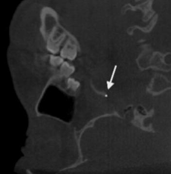
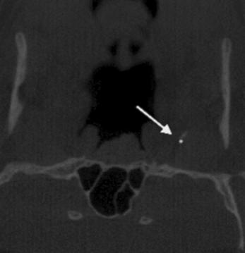
6 Stepanko and Lagravère Sphenoid bone changes in maxillary expansion landmark positions. The landmarks used in the present study are defined in Table 2 and shown in Figures 1 3. The principal investigator located the landmarks on each image. The intra-examiner reliability of landmark identification was determined by measuring ten randomly selected images, each repeated three times. Comparisons between different time-points and between patients were made by calculating distances and angles formed by the landmark coordinates. The distance, d, was determined using the following equation: X1 -X2 2 Y1 -Y2 2 Z1 -Z2 2 Intra-examiner reliability values were determined using the intraclass correlation coefficient (ICC). Mean differences between two time-points were obtained for each distance measured (T2 T1). Statistical analysis The sole examiner (LS) was standardized, as pre viously mentioned, with 10 randomized patients, each completed at 3 separate times. Once the patients were A B Figure 1. A frontal slice of the foramina rotundum, pterygoid canals, and optic canals in an ortho slice (A) and a volume-rendered image (B). A B Figure 2. A coronal slice demonstrating the foramina ovale and foramina spinosum landmarks in an ortho slice (A) and a volume-rendered image (B) on AVIZO software (FEI Company, Hillsboro, OR, USA). 274

 Distance number 1 Change (mm) Between foramina ovales 0.25 ± 1.")
7 Stepanko and Lagravère Sphenoid bone changes in maxillary expansion A B Figure 3. A coronal slice showing the pterygoid plate landmarks at the anterior and posterior of both the medial and lateral plates. A, Orthoslice of the landmarked structure. B, Three-dimensional view of the landmarked structure. Table 3. Descriptive statistics for changes in distances measured between T1 and T2 Distance (T1 T2) Distance number 1 Change (mm) Between foramina ovales 0.25 ± Vertical height right side, anterior of lateral plate to hypophysial fossa 0.78 ± Vertical height left side, anterior of lateral plate to hypophysial fossa 0.51 ± Anterior medial pterygoid plate distance 0.36 ± Posterior medial pterygoid plate distance 0.16 ± Anterior lateral pterygoid plate distance 0.56 ± Posterior lateral pterygoid plate distance 0.73 ± Left anterior, intra plates distance 0.07 ± Right anterior, intra plates distance 0.07 ± Left posterior, intra plates distance 0.13 ± Right posterior, intra plates distance 0.41 ± Right optic canal to right pterygoid canal 0.15 ± Left optic canal to left pterygoid canal 0.02 ± 1.06 Values are presented as mean ± standard deviation. evaluated, a 1-week interval was implemented before the second or third round of examination was under taken. This format was followed to ensure consistency in research. The ICC was calculated to determine the reliability of the 22 landmarks. Only two values calculated were below 0.90, with a reliability of the landmark location of at least 0.783, and the largest ICC mean measurement error was 2.32 mm. Descriptive statistics, ANOVA, a t -test, and univariate analysis were applied to the data collected. IBM SPSS Statistics 23.0 (IBM Co., Armonk, NY, USA) was used for statistical analysis. RESULTS The descriptive statistics summarized in Table 3 demonstrate that the largest mean measurement was calculated for distance 2, between the right hypophyseal fossa and the anterior edge of the right lateral pterygoid plate, with a mean value of 0.78 ± 1.78 mm. The largest 275
8 intra-plate distance was calculated for distance 11, between the right medial and lateral plates posteriorly, at 0.41 ± 1.46 mm. The largest transverse pterygoid plate distance was found between the posterior of the left and right plates, with a mean change of 0.73 ± 1.72 mm. The mean distance between the posteriors of the left and right medial plates was 0.16 ± 1.41 mm. Intraplate distances anteriorly were almost identical on the left and right, at 0.07 ± 0.85 mm and 0.07 ± 0.81 mm respectively. Table 4 shows the descriptive statistics for each treatment group. The largest mean change found was in the left vertical distance between the anterior of the left lateral plate and the left hypophyseal fossa, at 1.11 ± 2.16 mm. In the traditional expander group, this distance was 0.69 ± 1.45 mm, while in the control group it was only 0.54 ± 1.69 mm. The next largest distance was between the posteriors of the lateral pterygoid plates, at 1.01 ± 1.79 mm. In the traditional expander group, this distance was 0.35 ± 1.96 mm, and in the control group, it was 0.83 ± 1.40 mm. Univariate analysis yielded only three areas of statistical significance when correlating gender to distance observed, treatment to distance observed, or gender and treatment to distance observed. As described in Table 5, distance 2 (T 2 T 1 ) was statistically significantly correlated with sex and treatment (p = 0.012). Distances 4 and 8 also were also significantly correlated with sex and treatment, with p-values of and 0.033, respectively. DISCUSSION RME treatment-related structural changes have been measured using 2D radiographs and dental casts for many years, with each modality demonstrating limitations. Two-dimensional radiographs present many visual problems owing to the superimposition of structures and internal or external orientation errors, 10 whereas dental casts can only analyze dental changes with reference to other structures found on the cast itself. Few studies exist where the effects of RME on the facial complex have been studied using 3D imaging. Schlicher et al. 11 reported 3D CT to be accurate and reproducible for landmark placement for the analysis of bony structures. CBCT provides clinicians with a means to measure distances between anatomical landmarks, eliminating the drawbacks of traditional auxiliary examinations, thus ensuring more reliable and accurate measurements. The use of CBCT allows clinicians to analyze different bony structures, eliminating the undesirable factor of superimposition. This is especially true in the case of the sphenoid bone, where 3D imaging allows for the changes or effects of treatment to be visualized solely on the bone itself. In the present study, the landmarks were tested for reliability with an ICC. This study included a tooth-borne expander group, a bone-borne expander group, and a control group. Both tooth- and bone-borne expanders have been proven to be clinically effective methods, 10 yet Lin et al. 12 Table 4. Descriptive statistics comparing treatment modalities (bone, traditional, and control) Change (mm) No Distance (T 1 T 2 ) Group A (BAME) Group B (TAME) Group C (control) 1 Between foramen ovales 0.28 ± ± ± Vertical height right side, anterior of lateral plate to hypophysial fossa 1.11 ± ± ± Vertical height left side, anterior of lateral plate to hypophysial fossa 0.81 ± ± ± Anterior medial pterygoid plate distance 0.48 ± ± ± Posterior medial pterygoid plate distance 0.21 ± ± ± Anterior lateral pterygoid plate distance 0.25 ± ± ± Posterior lateral pterygoid plate distance 1.01 ± ± ± Left anterior, intra plates distance 0.15 ± ± ± Right anterior, intra plates distance 0.06 ± ± ± Left posterior, intra plates distance 0.03 ± ± ± Right posterior, intra plates distance 0.57 ± ± ± Right optic canal to right pterygoid canal 0.27 ± ± ± Left optic canal to left pterygoid canal 0.13 ± ± ± 1.05 Values are presented as mean ± standard deviation. BAME, Bone-anchored maxillary expander; TAME, traditional tooth-anchored maxillary expander. 276
9 Table 5. Statistical significance of treatment modalities and sex correlations Distance (T 1 T 2 ) Correlation Significance 1 Gender Treatment Gender Treatment Gender Treatment Gender Treatment Gender Treatment Gender Treatment Gender Treatment Gender Treatment Gender Treatment Gender Treatment Gender Treatment Gender Treatment Gender Treatment Gender Treatment Gender Treatment Gender Treatment Gender Treatment Gender Treatment Gender Treatment Gender Treatment Gender Treatment Gender Treatment Gender Treatment Gender Treatment Gender Treatment Gender Treatment demonstrated that patients later in adolescence exhibited larger skeletal movement with less dentoalveolar aftereffects from bone-borne expanders. Lagravère et al. 3 found that there was no clinical difference in expansion of the dentition between a TAME and a BAME. The primary difference found between the appliances was increased expansion of the upper first premolar in the tooth-anchored group compared to the other groups. Furthermore, Lagravère et al. 3 reported tipping in the molars after both bone and tooth-borne expanders, and Nada et al. 13 reported an average increase of 9.7% in the nasal airway with hyrax expanders. As measured in crosssection, pharynx enlargement has been reported to be 16.96% and 24.87% at the middle and lower levels, respectively. 14 This suggested the possibility that forces created by RME could be transferred to other bony structures. As the sphenoid bone is attached directly posterior to the maxilla via the pterygoid plates, examining the effects of RME on the sphenoid seemed logical. Although the true anchoring effect of the pterygoid plates during RME is still under debate, other studies 15,16 have concluded that it is a major source of resistance during expansion of the maxilla. Lee et al. 17 used finite element analysis to confirm there are higher stresses in the pterygoid region during expansion. Ghoneima et al. 2 found negligible expansion of the pterygomaxillary suture as a result of RME, leading to the possibility of force being transferred directly posterior through the suture. An attempt was made to determine whether any of the forces created during RME were being transmitted posteriorly causing expansion of the sphenoid. To analyze this process, the sphenoid was fully captured through the inclusion of landmarks on the greater and lesser wings as well as the pterygoid plates. Focus was placed on the plates due to their close proximity to the maxilla. It should also be noted that landmarks were placed in the coronal and frontal planes to ensure proper analysis. The largest mean change was found in the vertical distance between the anterior of the right lateral pterygoid plate and the right edge of the hypophyseal fossa, at 0.78 mm (Table 2). Comparing this to the vertical distance on the left side between the lateral plate and hypophyseal fossa at 0.51 mm (Table 2), it is reasonable to assume this was an artifact of analysis, and thus is of no clinical importance. This vertical distance is also described in Table 3, where the boneborne expander was associated with a mean change in height of 1.11 ± 2.16 mm. It is interesting to note that the largest mean change was in a vertical distance, rather than a transverse one. This is an indication of the limited capacity for force to be transferred through the maxilla to the sphenoid during RME. It was thought that if any change occurred it would 277
10 be located in the anterior of the sphenoid bone, particularly the pterygoid plates. Although this structure occurs bilaterally, there is no central suture to allow for expansion. It has been previously reported that the pterygoid plates are subject to bending anteriorly, further away from the body of the sphenoid. 18 The distances from the pterygoid fossa (the space between the medial and lateral pterygoid plates) to landmarks on each plate, medial and lateral at the anterior and posterior borders were analyzed. With the largest average intra-plate change discovered at 0.41 mm (Table 2), it was confirmed that there was no widening of the pterygoid plates due to RME, in either the anterior or posterior pterygoid fossa. When comparing the different treatment modalities, as seen between the foramina ovale (Table 3), the boneborne, tooth-borne, and control groups all exhibited relatively similar results, with average distance changes of 0.28 ± 1.39 mm, 0.24 ± 0.88 mm, and 0.24 ± 1.12 mm respectively. While no comparison of the efficacy of the treatment modalities was performed, as this was not the purpose of the study, it was observed that neither the bone nor tooth expanders resulted in noticeable changes in the sphenoid. Overall, this study yielded findings different from those of Leonardi et al. 8 The age range tested differed between the two studies, with the current study having an older population. Furthermore, the present study analyzed different areas of the sphenoid bone. This study did not quantify the force of the RME treatment on the sphenoid directly, but it did analyze potential changes created if forces were present. It is probable that a slight amount of force is transmitted posteriorly, but because of the sphenoid s size and interdigitation among intracranial bony structures, the force does not reach the threshold needed to produce noticeable movement. In either of the proposed possibilities of no force or a very slight force reaching the sphenoid, the outcome is still no clinical change. The preceding descriptive statistics are sufficient evidence that no clinical movement occurred due to the maxilla expanding. With a maximum mean value of 0.78 mm, which actually represents a vertical distance rather than a horizontal one, there is no clinical relevance in sphenoid bone changes as a result of RME. The univariate analysis demonstrated correlations between treatment and sex and three distances, which was merely a statistical finding rather than a clinical one. Although the present study used CBCT in patients, this is not common practice in the clinical scenario. Given the risks associated with ionizing radiation, obtaining frequent radiograms is not recommended. CONCLUSION The analysis provided evidence that there were no clinically significant changes in the sphenoid bone due to the RME treatments investigated, regardless of sex or treatment type. REFERENCES 1. Angell EH. Treatment of irregularity of the permanent or adult teeth. Dent Cosmos 1860;1: Ghoneima A, Abdel-Fattah E, Hartsfield J, El- Bedwehi A, Kamel A, Kula K. Effects of rapid maxillary expansion on the cranial and circummaxillary sutures. Am J Orthod Dentofacial Orthop 2011;140: Lagravère MO, Gamble J, Major PW, Heo G. Transverse dental changes after tooth-borne and boneborne maxillary expansion. Int Orthod 2013;11: Lione R, Ballanti F, Franchi L, Baccetti T, Cozza P. Treatment and posttreatment skeletal effects of rapid maxillary expansion studied with low-dose computed tomography in growing subjects. Am J Orthod Dentofacial Orthop 2008;134: Timms DJ, Preston CB, Daly PF. A computed tomographic assessment of maxillary movement induced by rapid expansion - a pilot study. Eur J Orthod 1982;4: Merrett SJ, Drage NA, Durning P. Cone beam computed tomography: a useful tool in orthodontic diagnosis and treatment planning. J Orthod 2009; 36: Gribel BF, Gribel MN, Frazäo DC, McNamara JA Jr, Manzi FR. Accuracy and reliability of craniometric measurements on lateral cephalometry and 3D measurements on CBCT scans. Angle Orthod 2011; 81: Leonardi R, Cutrera A, Barbato E. Rapid maxillary expansion affects the spheno-occipital synchondrosis in youngsters. A study with low-dose computed tomography. Angle Orthod 2010;80: Magnusson A, Bjerklin K, Kim H, Nilsson P, Marcusson A. Three-dimensional assessment of transverse skeletal changes after surgically assisted rapid maxillary expansion and orthodontic treatment: a prospective computerized tomography study. Am J Orthod Dentofacial Orthop 2012;142: Gunyuz Toklu M, Germec-Cakan D, Tozlu M. Periodontal, dentoalveolar, and skeletal effects of tooth-borne and tooth-bone-borne expansion appliances. Am J Orthod Dentofacial Orthop 2015;148: Schlicher W, Nielsen I, Huang JC, Maki K, Hatcher 278
11 DC, Miller AJ. Consistency and precision of landmark identification in three-dimensional cone beam computed tomography scans. Eur J Orthod 2012;34: Lin L, Ahn HW, Kim SJ, Moon SC, Kim SH, Nelson G. Tooth-borne vs bone-borne rapid maxillary expanders in late adolescence. Angle Orthod 2015; 85: Nada RM, van Loon B, Schols JG, Maal TJ, de Koning MJ, Mostafa YA, et al. Volumetric changes of the nose and nasal airway 2 years after toothborne and bone-borne surgically assisted rapid maxillary expansion. Eur J Oral Sci 2013;121: Vinha PP, Faria AC, Xavier SP, Christino M, de Mello- Filho FV. Enlargement of the Pharynx resulting from surgically assisted rapid maxillary expansion. J Oral Maxillofac Surg 2016;74: Lima SM Jr, de Moraes M, Asprino L. Photoelastic analysis of stress distribution of surgically assisted rapid maxillary expansion with and without separation of the pterygomaxillary suture. J Oral Maxillofac Surg 2011;69: Seeberger R, Kater W, Davids R, Thiele OC. Long term effects of surgically assisted rapid maxillary expansion without performing osteotomy of the pterygoid plates. J Craniomaxillofac Surg. 2010;38: Lee SC, Park JH, Bayome M, Kim KB, Araujo EA, Kook YA. Effect of bone-borne rapid maxillary expanders with and without surgical assistance on the craniofacial structures using finite element analysis. Am J Orthod Dentofacial Orthop 2014;145: Bishara SE, Staley RN. Maxillary expansion: clinical implications. Am J Orthod Dentofacial Orthop 1987;91:
Three-dimensional analysis of effects of rapid maxillary expansion on facial sutures and bones A systematic review
 Systematic Review Article Three-dimensional analysis of effects of rapid maxillary expansion on facial sutures and bones A systematic review Farhan Bazargani a ; Ingalill Feldmann b ; Lars Bondemark c
Does hyrax expansion therapy affect maxillary sinus volume? A cone-beam computed tomography report
 Imaging Science in Dentistry 2012; 42 : 83-8 http://dx.doi.org/10.5624/isd.2012.42.2.83 Does hyrax expansion therapy affect maxillary sinus volume? A cone-beam computed tomography report Drew M. Darsey,
Changes of the Transverse Dental Arch Dimension, Overjet and Overbite after Rapid Maxillary Expansion (RME)
") Dental Journal Changes of the Transverse Dental Arch Dimension, Overjet and Overbite after Rapid Maxillary Expansion (RME) Department of Advanced General Dentistry Faculty of Dentistry, Mahidol University.
Dental Journal Changes of the Transverse Dental Arch Dimension, Overjet and Overbite after Rapid Maxillary Expansion (RME) Department of Advanced General Dentistry Faculty of Dentistry, Mahidol University.
Normal orbit skeletal changes in adolescents as determined through cone-beam computed tomography
 Lee et al. Head & Face Medicine (2016) 12:32 DOI 10.1186/s13005-016-0130-0 RESEARCH Open Access Normal orbit skeletal changes in adolescents as determined through cone-beam computed tomography B. Lee 1,
Skull-2. Norma Basalis Interna Norma Basalis Externa. Dr. Heba Kalbouneh Associate Professor of Anatomy and Histology
 Skull-2 Norma Basalis Interna Norma Basalis Externa Dr. Heba Kalbouneh Associate Professor of Anatomy and Histology Norma basalis interna Base of the skull- superior view The interior of the base of the
Case Report: Long-Term Outcome of Class II Division 1 Malocclusion Treated with Rapid Palatal Expansion and Cervical Traction
 Case Report Case Report: Long-Term Outcome of Class II Division 1 Malocclusion Treated with Rapid Palatal Expansion and Cervical Traction Roberto M. A. Lima, DDS a ; Anna Leticia Lima, DDS b Abstract:
Anatomy and Physiology. Bones, Sutures, Teeth, Processes and Foramina of the Human Skull
 Anatomy and Physiology Chapter 6 DRO Bones, Sutures, Teeth, Processes and Foramina of the Human Skull Name: Period: Bones of the Human Skull Bones of the Cranium: Frontal bone: forms the forehead and the
Infratemporal fossa: Tikrit University college of Dentistry Dr.Ban I.S. head & neck Anatomy 2 nd y.
 Infratemporal fossa: This is a space lying beneath the base of the skull between the lateral wall of the pharynx and the ramus of the mandible. It is also referred to as the parapharyngeal or lateral pharyngeal
International Journal of Current Medical and Pharmaceutical Research
 ISSN: 2395-6429 International Journal of Current Medical and Pharmaceutical Research Available Online at http://www.journalcmpr.com DOI: http://dx.doi.org/10.24327/23956429.ijcmpr20170169 RESEARCH ARTICLE
AAO 115th Annual Session San Francisco, CA May 17 (Sunday), 1:15-2:00 pm, 2015
, 1:15-2:00 pm, 2015") AAO 115th Annual Session San Francisco, CA May 17 (Sunday), 1:15-2:00 pm, 2015 Title: Clinical and iomechanical Considerations of TADs in Challenging Cases: Sagittal Correction beyond Orthodontic oundaries
AAO 115th Annual Session San Francisco, CA May 17 (Sunday), 1:15-2:00 pm, 2015 Title: Clinical and iomechanical Considerations of TADs in Challenging Cases: Sagittal Correction beyond Orthodontic oundaries
Temporal fossa Infratemporal fossa Pterygopalatine fossa Terminal branches of external carotid artery Pterygoid venous plexus
 Outline of content Temporal fossa Infratemporal fossa Pterygopalatine fossa Terminal branches of external carotid artery Pterygoid venous plexus Boundary Content Communication Mandibular division of trigeminal
Cephalometric Analysis
 Cephalometric Analysis of Maxillary and Mandibular Growth and Dento-Alveolar Change Part III In two previous articles in the PCSO Bulletin s Faculty Files, we discussed the benefits and limitations of
A cone-beam computed tomography evaluation of buccal bone thickness following maxillary expansion
 Imaging Science in Dentistry 2013; 43: 85-90 http://dx.doi.org/10.5624/isd.2013.43.2.85 A cone-beam computed tomography evaluation of buccal bone thickness following maxillary expansion Sercan Akyalcin,
 www.oralradiologists.com CONE BEAM CT REPORT CASE XXXX Patient information Patient Name: - Referring Doctor: - Patient DOB: - Scan Date: [Start date] Reason for Exam: Maxillary facial pain Doctor Notes:
Anatomic Relations Summary. Done by: Sohayyla Yasin Dababseh
 Anatomic Relations Summary Done by: Sohayyla Yasin Dababseh Anatomic Relations Lecture 1 Part-1 - The medial wall of the nose is the septum. - The vestibule lies directly inside the nostrils (Nares). -
Skeletal Changes after Rapid Maxillary Expansion and Fixed Orthodontic Treatment: A CBCT Study
 Loma Linda University TheScholarsRepository@LLU: Digital Archive of Research, Scholarship & Creative Works Loma Linda University Electronic Theses, Dissertations & Projects 9-204 Skeletal Changes after
Mohammad Hisham Al-Mohtaseb. Lina Mansour. Reyad Jabiri. 0 P a g e
 2 Mohammad Hisham Al-Mohtaseb Lina Mansour Reyad Jabiri 0 P a g e This is only correction for the last year sheet according to our record. If you already studied this sheet just read the yellow notes which
Chapter 7 Part A The Skeleton
 Chapter 7 Part A The Skeleton Why This Matters Understanding the anatomy of the skeleton enables you to anticipate problems such as pelvic dimensions that may affect labor and delivery The Skeleton The
Dr.Noor Hashem Mohammad Lecture (5)
") Dr.Noor Hashem Mohammad Lecture (5) 2016-2017 If the mandible is discarded, the anterior part of this aspect of the skull is seen to be formed by the hard palate. The palatal processes of the maxillae
Dr.Noor Hashem Mohammad Lecture (5) 2016-2017 If the mandible is discarded, the anterior part of this aspect of the skull is seen to be formed by the hard palate. The palatal processes of the maxillae
Visibility of Maxillary and Mandibular Anatomical Landmarks in Digital Panoramic Radiographs: A Retrospective Study
 Visibility of Maxillary and Mandibular Anatomical Landmarks in Digital Panoramic Radiographs: A Retrospective Study Srisha Basappa, Smitha JD, Nishath Khanum*, Santosh Kanwar, Mahesh MS and Archana Patil
Research Article Length and Geometric Patterns of the Greater Palatine Canal Observed in Cone Beam Computed Tomography
 International Dentistry Volume 2010, Article ID 292753, 6 pages doi:10.1155/2010/292753 Research Article Length and Geometric Patterns of the Greater Palatine Canal Observed in Cone Beam Computed Tomography
Dental tipping and rotation immediately after surgically assisted rapid palatal expansion
 European Journal of Orthodontics 25 (2003) 353 358 2003 European Orthodontic Society Dental tipping and rotation immediately after surgically assisted rapid palatal expansion Chun-Hsi Chung and Adena M.
KJLO. A Sequential Approach for an Asymmetric Extraction Case in. Lingual Orthodontics. Case Report INTRODUCTION DIAGNOSIS
 KJLO Korean Journal of Lingual Orthodontics Case Report A Sequential Approach for an Asymmetric Extraction Case in Lingual Orthodontics Ji-Sung Jang 1, Kee-Joon Lee 2 1 Dream Orthodontic Clinic, Gimhae,
Original Article. Hoon Kim a Kyung-Suk Cha b. Key words: Class III malocclusion, Orthognathic surgery, Osteotomy, Segmental Le Fort I osteotomy
 Original Article THE KOREAN JOURNAL of ORTHODONTICS pissn 2234-7518 eissn 2005-372X https://doi.org/10.4041/kjod.2018.48.1.63 Evaluation of the stability of maxillary expansion using cone-beam computed
PTERYGOPALATINE FOSSA
 PTERYGOPALATINE FOSSA Outline Anatomical Structure and Boundaries Foramina and Communications with other spaces and cavities Contents Pterygopalatine Ganglion Especial emphasis on certain arteries and
Temporal region. temporal & infratemporal fossae. Zhou Hong Ying Dept. of Anatomy
 Temporal region temporal & infratemporal fossae Zhou Hong Ying Dept. of Anatomy Temporal region is divided by zygomatic arch into temporal & infratemporal fossae. Temporal Fossa Infratemporal fossa Temporal
A correlation between a new angle (S-Gn-Go angle) with the facial height
 with the facial height") A correlation between a new angle (S-Gn-Go angle) with the facial height Esraa S. Jassim B.D.S., M.Sc. (1) Marwan S. Al-Daggistany B.D.S., M.Sc. (1) Jinan E. Saloom B.D.S., M.Sc. (1) ABSTRACT Background:
A correlation between a new angle (S-Gn-Go angle) with the facial height Esraa S. Jassim B.D.S., M.Sc. (1) Marwan S. Al-Daggistany B.D.S., M.Sc. (1) Jinan E. Saloom B.D.S., M.Sc. (1) ABSTRACT Background:
Distribution of the maxillary artery related to sinus graft surgery for implantation
 42 Distribution of the maxillary artery related to sinus graft surgery for implantation LvingWell Dental Hospital LivingWell Institute of Dental Research Jang-yeol Lee, Hyoun-chull Kim, Il-hae Park, Sang-chull
Correction of Crowding using Conservative Treatment Approach
 Case Report Correction of Crowding using Conservative Treatment Approach Dr Tapan Shah, 1 Dr Tarulatha Shyagali, 2 Dr Kalyani Trivedi 3 1 Senior Lecturer, 2 Professor, Department of Orthodontics, Darshan
Bones of the skull & face
 Bones of the skull & face Cranium= brain case or helmet Copyright The McGraw-Hill Companies, Inc. Permission required for reproduction or display. The cranium is composed of eight bones : frontal Occipital
Original Research THE USE OF REFORMATTED CONE BEAM CT IMAGES IN ASSESSING MID-FACE TRAUMA, WITH A FOCUS ON THE ORBITAL FLOOR FRACTURES
 DOI: 10.15386/cjmed-601 Original Research THE USE OF REFORMATTED CONE BEAM CT IMAGES IN ASSESSING MID-FACE TRAUMA, WITH A FOCUS ON THE ORBITAL FLOOR FRACTURES RALUCA ROMAN 1, MIHAELA HEDEȘIU 1, FLOAREA
Chapter 7: Head & Neck
 Chapter 7: Head & Neck Osteology I. Overview A. Skull The cranium is composed of irregularly shaped bones that are fused together at unique joints called sutures The skull provides durable protection from
Skeletal System: Skull.
 Skeletal System: Skull www.fisiokinesiterapia.biz Bones of the Skull SPLANCHNOCRANIUM Nasal (2) Maxilla (2) Lacrimal (2) Zygomatic (2) Palatine (2) Inferior concha (2) Vomer Mandible NEUROCRANIUM Frontal
APPENDICULAR SKELETON 126 AXIAL SKELETON SKELETAL SYSTEM. Cranium. Skull. Face. Skull and associated bones. Auditory ossicles. Associated bones.
 SKELETAL SYSTEM 206 AXIAL SKELETON 80 APPENDICULAR SKELETON 26 Skull Skull and associated s 29 Cranium Face Auditory ossicles 8 4 6 Associated s Hyoid Thoracic cage 25 Sternum Ribs 24 Vertebrae 24 column
Structure Location Function
 Frontal Bone Cranium forms the forehead and roof of the orbits Occipital Bone Cranium forms posterior and inferior portions of the cranium Temporal Bone Cranium inferior to the parietal bone forms the
Dr.Ban I.S. head & neck anatomy 2 nd y جامعة تكريت كلية طب االسنان مادة التشريح املرحلة الثانية أ.م.د. بان امساعيل صديق 6102/6102
 جامعة تكريت كلية طب االسنان مادة التشريح املرحلة الثانية أ.م.د. بان امساعيل صديق 6102/6102 Pterygopalatine fossa: The pterygopalatine fossa is a cone-shaped depression, It is located between the maxilla,
EXPANSION. Effective Management of Transverse Problems in the Growing Patient: Evidence-based Approach
 Effective Management of Transverse Problems in the Growing Patient: Evidence-based Approach Lorenzo Franchi, DDS, PhD The transverse deficiency of the maxillary arch is the most common occlusal problem
Dr. Sami Zaqout, IUG Medical School
 The skull The skull is composed of several separate bones united at immobile joints called sutures. Exceptions? Frontal bone Occipital bone Vault Cranium Sphenoid bone Zygomatic bones Base Ethmoid bone
CASE REPORT. CBCT-Assisted Treatment of the Failing Long Span Bridge with Staged and Immediate Load Implant Restoration
 Computer Aided Implantology Academy Newsletter - Newsletter 20 - July 2009 CASE REPORT CBCT-Assisted Treatment of the Failing Long Span Bridge with Staged and Immediate Load Implant Restoration Case Report
Maxillary Sinus Measurements in Different Age Groups of Human Cadavers
 Tikrit Journal for Dental Sciences 1(2013)107-112 Maxillary Sinus Measurements in Different Age Groups of Human Cadavers Mohammad A. Abd-alla BDS, MSc., Ph.D. (1) Abdul-Jabbar J. Mahdi BDS, MSc., Ph.D.
Quantitation of transverse maxillary dimensions using computed tomography: a methodological and reproducibility study
 European Journal of Orthodontics 26 (2004) 209 215 European Journal of Orthodontics vol. 26 no. 2 European Orthodontic Society 2004; all rights reserved. Quantitation of transverse maxillary dimensions
Does a correlation exist between nasal airway volume and craniofacial morphology: A cone beam computed tomography study
 Original Research Does a correlation exist between nasal airway volume and craniofacial morphology: A cone beam computed tomography study Jeenal V Gupta, Makhija PG, Gupta KC 1 Departments of Orthodontics
Introduction to Local Anesthesia and Review of Anatomy
 5-Sep Introduction and Anatomy Review 12-Sep Neurophysiology and Pain 19-Sep Physiology and Pharmacology part 1 26-Sep Physiology and Pharmacology part 2 Introduction to Local Anesthesia and Review of
The orbit-1. Dr. Heba Kalbouneh Assistant Professor of Anatomy and Histology
 The orbit-1 Dr. Heba Kalbouneh Assistant Professor of Anatomy and Histology Orbital plate of frontal bone Orbital plate of ethmoid bone Lesser wing of sphenoid Greater wing of sphenoid Lacrimal bone Orbital
Changes in Lip, Cheek, and Tongue Pressures After Rapid Maxillary Expansion Using a Diaphragm Pressure Transducer
 Original Article Changes in Lip, Cheek, and Tongue Pressures After Rapid Maxillary Expansion Using a Diaphragm Pressure Transducer Nazan Küçükkeleş, DDS, PhD a ; Cenk Ceylanoğlu, DDS b Abstract: The purpose
Dental and Buccal Bone Stability After Rapid Maxillary Expansion and Fixed Orthodontic Treatment
 Loma Linda University TheScholarsRepository@LLU: Digital Archive of Research, Scholarship & Creative Works Loma Linda University Electronic Theses, Dissertations & Projects 8-1-2012 Dental and Buccal Bone
Mixed Dentition Treatment and Habits Therapy
 Interception Mixed Dentition Treatment and Habits Therapy Anterior Crossbites Posterior Crossbites Interference s with Normal Eruption Habit Therapy Tsung-Ju Hsieh, DDS, MSD 1 2 Anterior Crossbites Anterior
Skull-2. Norma Basalis Interna. Dr. Heba Kalbouneh Assistant Professor of Anatomy and Histology
 Skull-2 Norma Basalis Interna Dr. Heba Kalbouneh Assistant Professor of Anatomy and Histology Norma basalis interna Base of the skull- superior view The interior of the base of the skull is divided into
Palatal Depth and Arch Parameter in Class I Open Bite, Deep Bite and Normal Occlusion
 26 Iraqi Orthod J 1(2) 2005 Palatal Depth and Arch Parameter in Class I Open Bite, Deep Bite and Normal Occlusion Ahmad A. Abdulmawjood, a Mahmood K. Ahmed, a and Ne am R. Al-Saleem a Abstract: This study
A SIMPLE METHOD FOR CORRECTION OF BUCCAL CROSSBITE OF MAXILLARY SECOND MOLAR
 Short Communication International Journal of Dental and Health Sciences Volume 01,Issue 03 A SIMPLE METHOD FOR CORRECTION OF BUCCAL CROSSBITE OF MAXILLARY SECOND MOLAR Sumit Yadav 1,Davender Kumar 2,Achla
Evaluation of Cone Beam Computed Tomography in Diagnosis and Treatment Plan of Impacted Maxillary Canines
 Original Research Evaluation of Cone Beam Computed Tomography in Diagnosis and Treatment Plan of Impacted Maxillary Canines Seyed Hossein Hoseini Zarch 1, Farzin Heravi 2, Adineh Javadian Langaroodi 3,
The Position of Anatomical Porion in Different Skeletal Relationships. Tarek. EL-Bialy* Ali. H. Hassan**
 The Position of Anatomical Porion in Different Skeletal Relationships Tarek. EL-Bialy* Ali. H. Hassan** Abstract Previous research has shown that the position of glenoid fossa differs in different skeletal
Sample Case #1. Disclaimer
 ABO Sample Cases Disclaimer Sample Case #1 The following sample questions and answers were composed and vetted by a panel of experts in orthodontics and are intended to provide an example of the types
European Veterinary Dental College
 European Veterinary Dental College EVDC Training Support Document Preparation of Radiograph Sets (Cat and Dog) Document version : evdc-tsd-radiograph_positioning_(dog_and_cat)-20120121.docx page 1 of 13
Biology 218 Human Anatomy. Adapted from Martini Human Anatomy 7th ed. Chapter 6 The Skeletal System: Axial Division
 Adapted from Martini Human Anatomy 7th ed. Chapter 6 The Skeletal System: Axial Division Introduction The axial skeleton: Composed of bones along the central axis of the body Divided into three regions:
Do changes in spheno-occipital synchondrosis after rapid maxillary expansion affect the maxillomandibular complex?
 A. Silvestrini-Biavati, F. Angiero*, A. Gambino, A. Ugolini University of Genoa, Italy Department of Surgical Sciences, Orthodontics Unit *Department of Surgical Sciences, the University of Genoa, Italy
Low Dose Excellent Image Quality Rapid Reconstruction
 Low Dose Excellent Image Quality Rapid Reconstruction Efficient 3 in 1 Dental X-ray System CBCT > Precise 3-D Anatomical structures - Accurate diagnosis for doctors - Safe implant for patients > Significant
Extraoral Radiology October 10th, 2008
 Extraoral Radiology October 10th, 2008 Steven R. Singer, DDS srs2@columbia.edu 212.305.5674 November 8 th, 1895 Extraoral Projections Images can be produced in the dental office X-ray source can be Intraoral
Maxilla, ORBIT and infratemporal fossa. Neophytos C Demetriades MD, DDS, MSc Associate professor European University of Cyprus School of Medicine
 Maxilla, ORBIT and infratemporal fossa Neophytos C Demetriades MD, DDS, MSc Associate professor European University of Cyprus School of Medicine MAXILLA Superior, middle, and inferior meatus Frontal sinus
Omran Saeed. Luma Taweel. Mohammad Almohtaseb. 1 P a g e
 2 Omran Saeed Luma Taweel Mohammad Almohtaseb 1 P a g e I didn t include all the photos in this sheet in order to keep it as small as possible so if you need more clarification please refer to slides In
Arch dimensional changes following orthodontic treatment with extraction of four first premolars
 Received: 14 June. 2015 Accepted: 7 Dec. 2015 Arch dimensional changes following orthodontic treatment with extraction of four first premolars Abstract Asghar Ebadifar DDS, MSc 1, Mohammad Hossien Shafazand
Lingual correction of a complex Class III malocclusion: Esthetic treatment without sacrificing quality results.
 SM 3M Health Care Academy Lingual correction of a complex Class III malocclusion: Esthetic treatment without sacrificing quality results. Christopher S. Riolo, DDS, M.S, Ph.D. Dr. Riolo received his DDS
Monday Morning Pearls of Practice by Bobby Baig
 Dec 19, 2016 Monday Morning Pearls of Practice by Bobby Baig baig@buildyoursmile.com Prosthodontic Associates 2300 Yonge St, suite 905 Toronto, M4P1E4 www.buildyoursmile.com CBCT and Implant Dentistry:
Comparison between the external gonial angle in panoramic radiographs and lateral cephalograms of adult patients with Class I malocclusion
 425 Journal of Oral Science, Vol. 51, No. 3, 425-429, 2009 Original Comparison between the external gonial angle in panoramic radiographs and lateral cephalograms of adult patients with Class I malocclusion
Xbow Blended Two Phase The Other Way To Use Class II Springs
 Xbow Blended Two Phase The Other Way To Use Class II Springs Conflict of Interest Declaration I receive royalties from orthodontic labs that are licensed to fabricate the appliance discussed in this presentation.
Human, Male, White, Healed hammer blows
 Human, Male, White, Healed hammer blows Product Number: Specimen Evaluated: Skeletal Inventory: BC-217 Bone Clones replica 1 intact cranium General observations: In general, the molding process has preserved
Thakur H et al.applicability of various Mixed Dentition analysis among Sriganganagar School children
 Original Article APPLICABILITY OF MOYER S AND TANAKA-JOHNSTON MIXED DENTITION ANALYSIS IN SCHOOL CHILDREN OF SRI GANGANAGAR DISTRICT (RAJASTHAN) A PILOT STUDY Thakur H, Jonathan PT Postgraduate student,
Original Article. Jusuk Eom a Mohamed Bayome b,c Jae Hyun Park d,e Hee Jin Lim f Yoon-Ah Kook f Seong Ho Han g
 Original Article THE KOREAN JOURNAL of ORTHODONTICS pissn 2234-7518 eissn 2005-372X Displacement and stress distribution of the maxillofacial complex during maxillary protraction using palatal plates:
The conservative treatment of Class I malocclusion with maxillary transverse deficiency and anterior teeth crowding
 B B O C a s e R e p o r t The conservative treatment of Class I malocclusion with maxillary transverse deficiency and anterior teeth crowding Lincoln I. Nojima* Abstract This report describes the treatment
Cone Beam 3D Imaging
 Cone Beam 3D Imaging NewTom Sets the Standard in 3D Maxillofacial Imaging Cone Beam 3D Imaging The Global Market Leader The Inventors n of Cone Beam 3D In 1996, QR srl developed the first generation of
THE USE OF TEMPORARY ANCHORAGE DEVICES FOR MOLAR INTRUSION & TREATMENT OF ANTERIOR OPEN BITE By Eduardo Nicolaievsky D.D.S.
 THE USE OF TEMPORARY ANCHORAGE DEVICES FOR MOLAR INTRUSION & TREATMENT OF ANTERIOR OPEN BITE By Eduardo Nicolaievsky D.D.S. Skeletal anchorage, the concept of using the facial skeleton to control tooth
Trigeminal Nerve Worksheets, Distributions Page 1
 Trigeminal Nerve Worksheet #1 Distribution by Nerve Dr. Darren Hoffmann Dental Gross Anatomy, Spring 2013 We have drawn out each of the branches of CN V in lecture and you have an idea now for their basic
Introduction to Occlusion and Mechanics of Mandibular Movement
 Introduction to Occlusion and Mechanics of Mandibular Movement Dr. Pauline Hayes Garrett Department of Endodontics, Prosthodontics, and Operative Dentistry University of Maryland, Baltimore Assigned reading
#45 Ortho-Tain, Inc PREVENTIVE ERUPTION GUIDANCE -- PREVENTIVE OCCLUSAL DEVELOPMENT
 #45 Ortho-Tain, Inc. 1-800-541-6612 PREVENTIVE ERUPTION GUIDANCE -- PREVENTIVE OCCLUSAL DEVELOPMENT Analysis and Diagnosis of Occlusion: The ideal child of 5 y ears of age that probably has the best chance
Bones Ethmoid bone Inferior nasal concha Lacrimal bone Maxilla Nasal bone Palatine bone Vomer Zygomatic bone Mandible
 splanchnocranium - Consists of part of skull that is derived from branchial arches - The facial bones are the bones of the anterior and lower human skull Bones Ethmoid bone Inferior nasal concha Lacrimal
Application of augmented reality for inferior alveolar nerve block anesthesia: A technical note
 Technical Note pissn 2383-9309 eissn 2383-9317 J Dent Anesth Pain Med 2017;17(2):129-134 https://doi.org/10.17245/jdapm.2017.17.2.129 Application of augmented reality for inferior alveolar nerve block
Dental Data Checklist. UNIDENTIFIED PERSON FILE Data Collection Entry Guide. City, State, and ZIP. Street Address. FAX Number.
 Investigating Agency Agency Case Number Street Address City, State and Zip Telephone Number FAX Number Medical Examiner/Coroner Medical Examiner/Coroner Case Number Street Address City, State, and ZIP
Upper arch. 1Prosthodontics. Dr.Bassam Ali Al-Turaihi. Basic anatomy & & landmark of denture & mouth
 1Prosthodontics Lecture 2 Dr.Bassam Ali Al-Turaihi Basic anatomy & & landmark of denture & mouth Upper arch Palatine process of maxilla: it form the anterior three quarter of the hard palate. Horizontal
Dentoskeletal effects of a temporary skeletal anchorage devicesupported. rapid maxillary expansion appliance (TSADRME): A pilot.
: A pilot.") Dentoskeletal effects of a temporary skeletal anchorage devicesupported rapid maxillary expansion appliance (TSADRME): A pilot study Jason William Vassar a *; Anastasios Karydis b *; Terry Trojan c ; Jack
Dentoskeletal effects of a temporary skeletal anchorage devicesupported rapid maxillary expansion appliance (TSADRME): A pilot study Jason William Vassar a *; Anastasios Karydis b *; Terry Trojan c ; Jack
Canine Extrusion Technique with SmartClip Self-Ligating Brackets
 Canine Extrusion Technique with SmartClip Self-Ligating Brackets Dr. Luis Huanca Ghislanzoni Dr. Luis Huanca received his DDS in 2006 and the MS and Specialist in Orthodontics in 2009 from the University
Molar distalisation with skeletal anchorage
 Molar distalisation with skeletal anchorage Antonio Gracco, Lombardo Luca and Giuseppe Siciliani Department of Orthodontics, University of Ferrara, Ferrara, Italy Background: Distalisation of the upper
Prosthetic Options in Implant Dentistry. Hakimeh Siadat, DDS, MSc Associate Professor
 Prosthetic Options in Dentistry Hakimeh Siadat, DDS, MSc Associate Professor Dental Research Center, Department of Prosthodontics & Dental s Faculty of Dentistry, Tehran University of Medical Sciences
Human, Male, Single gunshot wound
 Human, Male, Single gunshot wound Product Number: Specimen Evaluated: Skeletal Inventory: BC-152 Bone Clones replica 1 intact cranium - left inferior nasal concha absent - middle nasal conchae absent 1
3D-MODEL CUSTOM-MADE MODELS SEGMENTATION AND PRODUCTION SERVICE OF BONE MODELS WITH HIGHEST 3D PRINTING RESOLUTION
 CUSTOM-MADE MODELS 3D-MODEL SEGMENTATION AND PRODUCTION SERVICE OF BONE MODELS WITH HIGHEST 3D PRINTING RESOLUTION FOLLOW US ON CUSTOM-MADE MODELS 3D-MODEL From a CT or CBCT scan, 3D-model service provides
Keywords Cone beam computed tomography, impacted maxillary canine, palatal depth and width
 32 Investigating the correlation between palatal depth and width measurements in impacted maxillary canine patients by using cone beam computed tomography 1 Omar Faruq Mohammed, B.D.S., 2 Alah Dawood Mahmood,
Benefits of CBCT in Implant Planning
 10.5005/jp-journals-10012-1032 CLINICAL SCIENCE 1 Gregori M Kurtzman, 2 Douglas F Dompkowski 1 Private General Practice in Silver Spring, Maryland, USA 2 Private Periodontal Practice in Bethesda, Maryland,
The Quality Leader in 3D Cone Beam CT
 The Quality Leader in 3D Cone Beam CT The Complete 2-in-1 or 3-in-1 Multi-modality Solution PreXion, with over 15 years of innovation in the medical and dental fields, introduces the PreXion3D Eclipse.
Invisalign technique in the treatment of adults with pre-restorative concerns
 Mampieri and Giancotti Progress in Orthodontics 2013, 14:40 REVIEW Open Access Invisalign technique in the treatment of adults with pre-restorative concerns Gianluca Mampieri * and Aldo Giancotti Abstract
Bisection of Head & Nasal Cavity 頭部對切以及鼻腔. 解剖學科馮琮涵副教授 分機
 Bisection of Head & Nasal Cavity 頭部對切以及鼻腔 解剖學科馮琮涵副教授 分機 3250 E-mail: thfong@tmu.edu.tw Outline: The structure of nose The concha and meatus in nasal cavity The openings of paranasal sinuses Canals, foramens
Original Article. Paschalis Pamporakis a ;Şirin Nevzatoğlu b ; Nazan Küçükkeleş c
 Original Article Three-dimensional alterations in pharyngeal airway and maxillary sinus volumes in Class III maxillary deficiency subjects undergoing orthopedic facemask treatment Paschalis Pamporakis
SARME - Hyrax expander treatment of severe transverse and sagittal maxillary deficiency: A case report
 Article ID: WMC004488 ISSN 2046-1690 SARME - Hyrax expander treatment of severe transverse and sagittal maxillary deficiency: A case report Peer review status: No Corresponding Author: Dr. Giorgia Calicchia,
Reliability of anatomic structures as landmarks in three-dimensional cephalometric analysis using CBCT
 Original Article Reliability of anatomic structures as landmarks in three-dimensional cephalometric analysis using CBCT Pegah Naji a ; Noura A. Alsufyani b ; Manuel O. Lagravère c ABSTRACT Objective: To
Biomechanical Analysis of Maxillary Expansion in CLP Patients
 Original Article Biomechanical Analysis of Maxillary Expansion in CLP Patients Christof Holberg a ; Nikola Holberg b ; Katja Schwenzer c ; Andrea Wichelhaus d ; Ingrid Rudzki-Janson e ABSTRACT Objective:
Miniscrews were initially proposed as a means
 From Planning to Delivery of a Bone-Borne Rapid Maxillary Expander in One Visit B. GIULIANO MAINO, MD, DDS EMANUELE PAOLETTO LUCA LOMBARDO, DDS GIUSEPPE SICILIANI, DDS Miniscrews were initially proposed
Dr.Sepideh Falah-kooshki
 Dr.Sepideh Falah-kooshki MAXILLA Premaxillary/median palatal suture (radiolucent). Incisive fossa and foramen (radiolucent). Nasal passages (radiolucent). Nasal septum (radiopaque). Anterior nasal spine
With judicious treatment planning, the clinical
 CLINICIAN S CORNER Selecting custom torque prescriptions for the straight-wire appliance Earl Johnson San Francisco, Calif Selecting custom torque prescriptions based on the treatment needs of each patient
HHS Public Access Author manuscript Am J Orthod Dentofacial Orthop. Author manuscript; available in PMC 2016 December 16.
 Effects of rapid maxillary expansion on the cranial and circummaxillary sutures Ahmed Ghoneima a, Ezzat Abdel-Fattah b, James Hartsfield c, Ashraf El-Bedwehi d, Ayman Kamel e, and Katherine Kula f a Lecturer,
Ectopic upper canine associated to ectopic lower second bicuspid. Case report
 Original Article Published on 15-06-2001 In Italiano, per favore En Español, por favor Ectopic upper canine associated to ectopic lower second bicuspid. Case report A.R. Mazzocchi* * MD DDS. Corresponding
Two- and Three-dimensional Orthodontic Imaging Using Limited Cone Beam Computed Tomography
 Original Article Two- and Three-dimensional Orthodontic Imaging Using Limited Cone Beam Computed Tomography Akira Nakajima a ; Glenn T. Sameshima b ; Yoshinori Arai c ; Yoshito Homme d ; Noriyoshi Shimizu