KNEE S MOTION PATH RELATIVE TO THE PASSIVE COUPLED KINEMATIC ENVELOPE
|
|
|
- Arthur Roberts
- 6 years ago
- Views:
Transcription
1 KNEE S MOTION PATH RELATIVE TO THE PASSIVE COUPLED KINEMATIC ENVELOPE By Kevin Dodd Submitted to the Department of Mechanical Engineering and the Graduate Faculty of the University of Kansas in partial fulfillment of the requirements for the degree of Masters of Science Dr. Lorin Maletsky, Advisor Dr. Lisa Friis, Committee member Dr. Sara Wilson, Committee member Date Approved
2 The Thesis Committee for Kevin Dodd certifies that this is the approved Version of the following thesis: KNEE S MOTION PATH RELATIVE TO THE PASSIVE COUPLED KINEMATIC ENVELOPE By Kevin Dodd Committee: Dr. Lorin Maletsky, Advisor Dr. Lisa Friis, Committee member Dr. Sara Wilson, Committee member Date Approved ii
3 Abstract Laxity assessments are done before, during, and after intervention of knee injuries to assess potential outcomes. Study objectives were to create a method to define the passive kinematic limits, without artificially constraining coupled motion, and describe motion relative to them. The coupled envelopes of internal/external (IE), varus/ valgus (VV), and anterior/ posterior (AP) motion and a neutral path were used to describe loaded lunges and a simulated walk cycle. The envelopes were created by manual manipulation to motion limits. Lunges with ±3.3 Nm IE torques and ±4.7 Nm VV torque were used to verify the IE-VV coupled kinematic envelope. The IE envelope compared well, while the VV envelope was constantly offset. For six of the eight knees, a repeatable internalvalgus-anterior path relative to the center of laxity was observed for the walk cycle. All eight displayed an average anterior displacement outside the boundary at mid-stance of 4.3 ± 5.0mm. iii
4 Acknowledgments This written document did not come about by the sole efforts of the author alone but by the encouragement, friship and guidance of many, to whom I owe a debt of gratitude. First to Dr. Lorin Maletsky for selecting me to be part of his research team and entrusting in me knowledge and growth, he is a man truly working out of his giftedness for many. To my committee members Dr. Lisa Friis and Sara Wilson along with other faculty that have taught me and guided me in this pursuit of this degree To the members of the Experimental Joint Biomechanics Research laboratory; Amit Mane for working long hours in the lab and a consistent source of encouragement, Amber Reeve for being an example of organization and thoroughness in tirelessly a pursuit of sound science, Chadd Clary for your leadership and humor, your lighthearted nature is infections and encouraging, Nathan Lenz for your time and effort to pass on your knowledge and experience, Nicholas Morton for your intellectual political orations. Working with you all has been a pleasure. To my wife Tonya, for your infinite love and support of your husband s silly ideas, you have seen something in me from the beginning and without fail you continue to call out the best of who I am. And to Avery, you have no idea how wildly you have changed my life forever. Finally if it were not a call to seek the better and strive towards a prize not clearly seen, I surly would have failed. Thanks be to God the giver of all good gifts. You have all been a good gift in my life. This work was funded by the National Science Foundation, Grant Number , under the IMAG program for Multiscale Modeling and DePuy Orthopaedics, Inc. iv
5 Table of Content Abstract... iii Acknowledgments... iv Table of Content... v List of Figures... vi List of Tables... xi List of Tables... xi List of Abbreviations... xii 1 Introduction Literature Review Passive Range of Motion Envelope of Motion and Laxity Methods in Assessing PROM Uses of the Envelope and Laxity in Model Validation Experimental Joint Biomechanics Research Lab Contribution Knee s Motion Paths Relative to the Passive Coupled Kinematic Envelope Introduction Material and Methods Results Comparison of QKR and Hand Manipulation Interdepent Measures QKR Lunges Walk Cycle Relative to Coupled Envelopes Discussion Tables and Figures Discussion / Conclusion References A Appix A1 Wrapping the Envelopes A1.1 Discretization A1.2 Wrapping A1.3 Smoothing Boundaries Between the Flexion Steps A1.4 Checking the Boundary A1.5 Wrapping Conclusion A2 Envelope Fit and Figures A3 Additional plots A4 Programs v
6 List of Figures Fig. 1 Experimental manual manipulation of specimen NK06L IE and VV coupled interactions Fig. 2 Experimental manual manipulation of specimen NK06L IE and AP coupled interactions Fig 3 Experimental manual manipulation of specimen NK06L VV and AP coupled interactions Fig. 4 Initial scatter plot on NK06L experimental data at 20 knee flexion for all envelopes Fig. 5 Initial wrapping of the scattered data for NK06L experimental data at 20 knee flexion for all envelopes Fig. 6 a-d. Final IE-VV, IE-AP, and VV-AP coupled kinematic envelope of NK06L at 20 flexion. The shaded regions were the laxity quadrants after smoothing. The black dots were the original experimental poses at 20 ± 1 of flexion. The VV-AP interdepency region (a), IE-VV interdepency (b) and the IE-AP interdepency (c) each had the final laxity regions shaded. An isometric view for the three envelopes together was shown in (d). The axes were in real units of tibial position relative to the anatomical coordinate frame of the femur. As seen, the projections still do not account for interdepencies of two or more axis of measurements Fig. 7 The full IE-VV coupled kinematic envelope for one specimen. The interdepencies at selected flexion steps (a-i). The numbers below the flexion cross section represent the number of data points within 2% of the boundary / the number of data points in the cross section / the number of data points that was used in the initial boundary wrapping. The complete assembled interdepencies shaded in blue (j). The flexion steps of 30, 60 and 100 were shown inside the IE-VV volume. The phase plot of the simulated walk cycle was shown relative to the boundary. The center of the interdepency was represented by the lines on the typically given envelope, shown in the grey shaded region on the IE and VV respective planes. It was clear to see the relationship between the valgus and internal laxity region in this figure. Also the walk cycle was observed mostly on the IE-VV envelope, indicating that constraints of the VV and IE motion were potentially guiding the motion path of the walk cycle vi
7 Fig. 8 Final smoothed laxity boundary of the IE-VV interdepencies for one specimen (NK06L). Included in the figure were the trials containing the QKR lunges and the KKS simulated walk cycle. The pattern of the paths were guided by the ligaments, articular geometry and other connective tissue as loads, no matter how small, are transmitted across the knee. This figure illustrates what was thought to be a relationship between the passive constraints (boundary) and normal amblitory motion (lines) Fig. 9 The normalized area of laxity was described as the fractional area of the interdepent area relative the maximum laxity range in the two DoF. The location of the indepent area relative to the interdepent area was of no concern. This illustration was for one specimen Fig. 10 Displacement measure of the activity relative to the kinematic envelope. These measurements were used in Table 4 and Fig. 20-Fig. 28. This figure was of a valgus loaded knee at 20 of flexion relative to the IE-VV kinematic envelope for one specimen. The measurements were that of the coupled DoF relative to the indepent IE and VV envelope and the coupled IE-VV envelope. VV ievv was the measurement of the VV displacement relative to the IE-VV envelope, whereas the VV vv was the VV displacement relative to the indepent VV envelope. The measurements were taken as polar measurements in that there is a direction (region of laxity) and magnitude either inside (negative) or outside (positive) from the boundary Fig. 11 Individual comparison of the IE envelopes of the lunge (solid) and the hand manipulation (dashed) for the knees that underwent the QKR portion of the protocol Fig. 12 Individual comparisons of the VV envelopes of the 4.7 Nm VV lunge (solid) and the hand manipulation (dashed) for the knees that underwent the QKR portion of the protocol Fig. 13 IE laxity of the hand manipulation compared to the QKR IE loaded lunges. Each color represents one specimen Fig. 14 VV laxity of the hand manipulation compared to the QKR VV loaded lunges. Each color represents one specimen. Note that NK02R did not have QKR VV laxity and therefore only the hand laxity was presented Fig. 15 Average laxity of all specimens as determined by the manual manipulation. (a) the mean rotational laxity associated with the VV (dotted line) and IE (solid line) with one standard deviation given by the shaded region. (b) The mean (solid line) and one standard deviation (shaded region) of the AP laxity vii
8 Fig. 16 Interdepent laxity regions as a fraction of the full range of motion in two axes for all specimens (refer to fig. 9 for the method of calculating). The shaded region was the mean (± one standard deviation) of all knees in the IE-VV (a), VV-AP (b), and IE-AP (c) interdepent normalized laxities. All knees were represented to show the patterns of the kinematic envelope interdepencies Fig. 17 Motion paths for the loaded lunges in the QKR for each test specimen (IE Lunges n=4, VV lunges n=3). The shaded regions were the range of each test. The flexion and extension coupled paths of the loaded lunges relative to the IE-VV (a), IE-AP (b), and VV-AP (c) envelopes. The flexion (solid) and extension (dashed) paths were shown relative to the center of the respective envelope. The y axis on each represents the laxity quadrant location of the activity relative to the center Fig. 18 Motion paths for the varus lunge (with respect to the IE-AP (a)) and internally lunge (with respect to the VV-AP (b)) for each test specimen (Int lunges n=4, Var lunges n=3). The flexion (solid) and extension (dashed) paths were shown relative to the center of the respective envelope. The y axis on each represents the laxity quadrant location of the activity relative to the center Fig. 19 No load lunge for each knee (n=4) in the QKR relative to the IE-AP(a), VV- AP(b), and IE-AP(c) envelopes. The flexion (solid) and extension (dashed) paths were shown relative to the center of the respective envelope Fig. 20 QKR externally loaded lunge kinematic displacement from respective envelopes for four specimens Fig. 21 QKR internally loaded lunge kinematic displacement from respective envelopes for four specimens Fig. 22 QKR varus loaded lunge kinematic displacement from respective envelopes for three specimens Fig. 23 QKR valgus loaded lunge kinematic displacement from respective envelopes for three specimens Fig. 24 QKR unloaded lunge kinematic displacement from respective envelopes for four specimens Fig. 25 The walk cycle coupled paths as compared to the IE-VV, VV-AP and IE-AP coupled passive kinematic envelope for all specimens. Figures represent the coupled path of the walking activity relative to the (a) IE-VV envelope, (b) VV- AP envelope, and (c) IE-AP envelope. The coupled path was represented at the direction relative to the center of the envelope viii
9 Fig. 26 The average (±one standard deviation) IE displacement of all knees relative to (a) the IE-VV envelope, (b) the IE-AP envelope, and (c) IE envelope for one walk cycle Fig. 27 The average (±one standard deviation) VV displacement of all knees relative to (a) the IE-VV envelope, (b) the VV-AP envelope, and (c) VV envelope for one walk cycle Fig. 28 The average (±one standard deviation) AP displacement of all knees relative to (a) the IE-AP envelope, (b) the VV-AP envelope, and (c) AP envelope for one walk cycle Fig. A1 Dotted lines are the concave (black) and convex (red) and the solid lines are the corresponding smoothed boundaries. The centers of the polygons are the x smoothed and o for the initial wrapping. As you can see on this data set all wrappings visually match well except for the concave region in the External and valgus pose. See figure 4 for a better view of how the smoothing alters the data wrapping. Other data sets are included in the appix Fig. A2 This plot is of the total laxity volume over the experimented flexion range (n-11). If the knee were to have 100% IE laxity in extension to flexion and 100% indepent VV laxity as well, then the Volume percentage would be 100%. Due to the interdepencies the percentages are less. Four conditions are considered with a convex and concave wrap and smoothing of each Fig. A3 Average number of data points that make up the surface of the laxity interdepencies boundary (n-11). All interdepencies were considered so the higher the percentage indicates the knee was posed such that at least one interdepent point was reached. Endpoint would be a pose in which the structures or geometry begins to restrict further motion. The filtered 5% and 2% indicate poses that are within 5% and 2 % respectively from the smoothed interdepency boundary. This is one check to make sure the smoothing step does not under or over estimate the interdepencies Fig. A4 Area of the IE VV and AP interdepencies for one specimen. These show how the concavities do not seem to play a large role in the surface generation as the smoothing does. The smoothing also removes discontinuities between flexion steps. All knees followed the same tr concerning the concave or convex wrapping Fig. A5 Density plot of number of experimental poses that is within 2% of the IE-AP boundary Fig. A8 Density plot of number of experimental poses that is within 2% of the IE-VV boundary ix
10 Fig. A9 Density plot of number of experimental poses that is within 2% of the VV-AP boundary x
11 List of Tables Table 1 Specimen vital information. Not all knees were used in the analysis as NK01R, NK04R, and DP09L were excluded from the analysis (see appix). Height and weight for NK02R were unknown 39 Table 2 RMS, RMS error, and correlation coefficient of the hand manipulation as compared to the loaded lunges (* p<.005). There were no values for shaded regions. 40 Table 3 Comparisons of different techniques in measured laxity. QKR ranges were for IE laxity (n=4) and VV laxity (n=3). Hand manipulation was the mean (± standard deviation) for the IE, VV and AP laxities (n=8). * Approximations from literature [6,52]. 40 Table 4 The mean (±standard deviation) of the activity relative to the laxity boundary. The displacement of the activity relative to a coupled kinematic envelope is noted by the kinematic DoF magnitude from the boundary relative to the IE-VV (ievv), IE-AP (ieap), VV-AP (vvap), IE (ie), VV (vv) or AP (ap) boundary. The light grey boxes indicate activities in which the loading was about the DoF under investigation relative to the boundaries that included that DoF kinematic envelope. The darker grey is the coupled displacements of the IE and VV squats relative its coupled envelope. Positive is external to the boundary and negative internal to the boundary. The larger the negative displacement the closer the pose is to the center of the kinematic envelope. 41 xi
12 List of Abbreviations DoF ACL Ant AP AP ap AP ieap AP vvap CD Ext Int IE IE ie IE ieap IE ievv IS KKS MCL ML MS Post PROM QKR Degree of Freedom Anterior cruciate ligament Anterior Anterior Posterior DoF Anterior Posterior displacement relative to the VV envelope Anterior Posterior displacement relative to the IE-VV envelope Anterior Posterior displacement relative to the VV-AP envelope Compression distraction DoF External Internal Internal External DoF Internal External displacement relative to the IE envelope Internal External displacement relative to the IE-AP envelope Internal External displacement relative to the IE-VV envelope Initial Swing phase Kansas Knee Simulator Medial collateral ligament Medial lateral DoF Mid-stance phase Posterior Passive range of motion Kansas Quasi-Static Knee Rig xii
13 RMS TKA TS TW Val Var VV VV ievv VV vv VV vvap Root mean square Total knee arthroplasty Terminal stance phase Terminal swing phase Valgus Varus Varus Valgus DoF Varus Valgus displacement relative to the IE-VV envelope Varus Valgus displacement relative to the VV envelope Varus Valgus displacement relative to the VV-AP envelope xiii
14 1 Introduction Injuries that affect the knee are common in daily activities, athletic activities, and working conditions. Knee injuries accounted for 543,000 emergency room visits in 2006 in the United States[1]. Another study found that 50,000 knee injuries required surgical intervention [2]. Overall 40% of the acute knee injuries are ligamentous, and of those 46% are anterior cruciate ligament (ACL) and 29% are medial collateral ligament (MCL) [3]. Further damage to the knee by injury or disease may warrant the need for a total knee arthroplasty (TKA). Between 1990 and 2004 there were 4.1 million TKA s and 8% of those were revisions [4]. Research and interventions have helped many improve there daily activity level. However, with the increasing population and rising injury rates, a better understanding of diagnostic and intervention practices are a must. The function of the knee has been described as a biological transmission that accepts and transmits loads across the lower limb. The muscles and soft tissues create and limit the motion in such a manner that enables locomotion [5]. The passive restraints of the knee are of importance in the role they play in transmitting ambulatory forces while maintaining a normal range of motion. Typical clinical evaluations, such as the Lachmans test, drawer test, pivot shift, and others, will assess structure integrity by manipulating the knee to its passive kinematic limits of motion. Understanding the role of the passive limits and the coupling nature of the structures working together during normal conditions are useful in determining diagnostic, functional parameters, and intervention outcome tools for those that are treating and researching the knees behavior. The soft tissue constrains have been shown to have both primary and secondary constraints thus creating coupled motion limits [6-10]. The ACL, for example, 1
15 primarily constrains the anterior motion and functions as an internal motion constraint. The MCL constrains external and anterior motion. These two ligaments, along with others contribute to the anterior motion limits of the knee. The passive envelope has been used to describe the function of these ligaments working in conjunction with one another [6]. The coupled motion constraint has been shown to be sensitive to experimental set up [11]. Therefore a method to determine kinematic limits without imposed external constriction is important. The objective of this research was to create a method to define the kinematic limits of the knee without artificially constricting coupled motion. The defined kinematic limits are then used as a base measurement from which ambulatory activities can be compared. The methods of this research will be used in future research of the Experimental Joint Biomechanical Research Lab in describing structure function and knee behavior. Currently kinetic envelopes are being used to describe how the structures limit motion under loaded activities. The outcome of these kinetic envelopes can be used in model validation. A review of literature identifies the uses, methods and definition of laxity assessment (Chapter 2). Chapter three describes the experimental set up and uses of the boundary in identifying motion paths that are guided by the ligamentous constraint. A discussion of the implications and future work conclude the description of the motion paths. Finally in the appix a more detailed description of the analysis are given so that the research started here can be continued and built upon as described in the concluding remarks. 2
16 2 Literature Review Investigation into the ligament passive function of the knee has led to many breakthroughs in rehabilitation, ligament repair, prosthetic design, and even exercise training and injury prevention. It is the ligaments, articular geometry, in combination with external loading and muscular activation that guides the motion enabling ambulatory activates. The complexities of these structures however, have led to many different avenues of investigation, deping, of course, on the expected outcome of the investigation. Passive range of motion (PROM) continues to be a comparative assessment that many investigators use, in one form or another. It is the passive constraint to motion that lays the foundation of understanding how the structures function and creates a point of reference readily realized in clinical applications. No matter the approach to understanding the knee function, PROM assessment is a must. This review highlights different approaches in literature that are commonly used to describe knee function and its relationship to clinical application and passive assessments, as well as the methods of capturing the PROM measurements. Finally the uses of PROM in defining laxity, envelope of motion, and coupled guiding motion is further defined as essential investigating activities in understanding knee function, within the scope of secondary constraint interactions. This review is inted to enlighten the reader on the approach, method and use of PROM in 3
17 identify knee passive secondary constraint function and behavior to better equip researchers and clinicians incurrent and future practices. 2.1 Passive Range of Motion Envelope of Motion and Laxity The term passive range of motion can be applied to a broad range of investigations dealing with a measurement of joint motion. PROM assessments are done routinely in clinical evaluations to determine gross limb motion limits, for the knee this is typically from full extension to a terminal flexion. In literature there are those that present PROM as a laxity, envelope of motion, or simply coupled guided flexion extension paths. The motion limit assessments include, internal-external (IE), varus-valgus (VV), anterior-posterior (AP), medial-lateral (ML), and compressiondistraction (CD relative to a flexion angle. There can be some misconceptions in interpreting the laxity, envelopes and motion paths as the same. Therefore it is important to differentiate between passive laxity, envelope of motion, and PROM literature. Passive knee laxity is the range between the maximum motion limits of the tibia in one degree of freedom (DoF) at a given flexion angle, as produced by the connective tissue upon minimal external loading conditions without any muscular or internal force activation. As defined by Daniel and Stone, the flexion angle is critical as the displacement limits varies with flexion angle [12]. Laxity is an point assessment in that the displacement between two limits (anterior and posterior, internal and external etc.) are used to identify the range of motion at a given flexion angle. Typical assessments include the AP drawer exam, VV, and IE stress test [13, 4
18 14]. These assessments are typically the initial indication that the connective tissue has been compromised. A compromised ligament has a reduced ability to constrain motion, thus increasing laxity in both the primary and secondary motion associated with that ligament. The point measurement is then represented as a single value at a given flexion angle. The envelope of motion on the other hand is a set of secondary tibia positional limits along the full flexion range, and the path associated with the motion limit. The positions between internal and external throughout the full flexion range bounds the IE envelope of motion. Blankevoort et al. describes the IE envelope of motion as a region of freedom-of-motion, where positions inside the region are less influenced by the knee stiffness and for positions outside the envelope the stiffness matters [11]. Paths inside the envelope are highly influenced by external loading, while paths along the envelope are reproducible and coupled. The pivot shift can be viewed as an envelope assessment as the knee is flexed while maintaining tissue limitation to an internal and valgus position. A subluxation, or feel of an abnormal boundary limit, indicates a possible ACL injury as indicated by a different stiffness feel of the knee [15-17]. The International Knee Documentation Committee grades the feel as a glide, clunk, and gross. Envelope boundaries t to influence subjective assessment of function and can be more difficult to quantify, in that a larger range of motion is used to identify the motion limits. Nielsen et al. defined three envelopes of motion in the AP, IE, and VV directions, yet presented only the laxity as a function of flexion [6]. The intention of 5
19 the study was to identify the functional aspects of the ligaments and connective tissue. In doing so it was observed that continuity of the DOF is lost when presented in numerical terms of laxity or when the maximum extent of movement is recorded regardless of the position of the knee joint in other aspects. Essentially there is lost coupling motion constraints of the ligaments when only observing one secondary motion limit. Inference is made to the primary and secondary motion restraint of the connective tissue and the effect all tissue has in the coupling of all secondary motions restraint. Blankevoort s envelope description only considered IE limits but suggested the other secondary motions limits were assessable [11]. The motion paths of the extreme internal and external pose of the knee were described for four knees and no noticeable correlation was found between the IE and VV coupled motion. Finally PROM has been represented as the passive flexion and extension path. The path of flexion is controlled by the ligaments and articular geometry, creating coupled secondary motion. Wilson et al. stated that a simple PROM or Freedom-ofmotion, (i.e. envelope of motion), does not show the extent of secondary coupled motion and found that as the knee is flexed there is a coupled motion between the primary and secondary motions [10]. A flexion extension path that is not influenced by external loads was shown to follow an IE path within 2, with proper experimental set up. The path exists inside the envelope of motion and is sensitive to experimental set up. Also it must be noted that the experiment did not include the influence of the patella femur interaction. 6
20 It is clear from literature that ligaments and articular geometries of the knee create secondary coupled motion constraints in the flexion-extension path, as well as an envelope of motion that is typically described in terms of laxity as a function of flexion angle. The coupling of all degrees of freedom is assumed in the study done by Nielsen and should be investigated further [6]. PROM assessments lead to better understanding of ligament function and create opportunity to improve existing clinical practices. The link of PROM and other activities exerting higher internal and external forces has yet to be quantified. 2.2 Methods in Assessing PROM Methods for assessing laxity and the envelope are similar and can include, but are not limited to, manual, instrumented manual, use of a loading rig or robotic manipulation. Testing differs deping on in vivo or in vitro examinations; however, the methods are fairly similar. Simple manual manipulation would be the least sophisticated, yet easiest to reproduce in a clinical environment. The tibia is maneuvered by the examiner with unknown forces to positions of structural restraint to further motion. In some cases a comparison of motion feel to the contralateral knee is used to make any judgments on ligament function. This method is quick and needs no special equipment to perform. However, as previously mentioned, the forces and displacements are not quantifiable, and therefore subjective and vulnerable to false indications of damage. The measurement system is the examiner and the flexion angle of the knee is assumed apart from a local knee coordinate system. 7
21 To better define the axis of loading and the loads applied, cadaveric researchers manipulated knees with instrumented handlebars, something that could not easily be done in clinical environments [6]. With defined displacement and loading, knee stiffness and ligament function can be identified. In many studies the manipulation of an intact knee would be compared to the ligament deficient knee. Still, the amount of force to manipulate the knee as to the extent the ligaments were restraining motion and accepting the manipulating forces was largely unknown. More refined loading and controlled measurements were needed. Loading rigs and fixtures manipulate the limb with controlled loads. The displacements were also measured along or about the axis of loading [11, 18, 19]. The benefit of the rigs are that the loads and the displacements satisfy the measurement system, initial joint position, motion constraints of the system, and applied forces; five of the six parameters outlined by Daniel and Stone [12]. In vitro muscular activation are simple to assume as marginal or null while in vivo studies muscular forces are difficult to quantify. While loading rigs may seem to quantify joint laxity the best, clinical application have not been as easily recognized. Most clinical laxity loading rigs examine the ACL function by measuring the anterior displacement at a given flexion, such as the KT-1000, while there are not many clinical rotational laxity devices [20-24]. As for all rigs, the motion constraint of the system can induce unwanted results [11, 25]. Therefore, caution should be used when using the displacement to describe ligament function. However, without such loading rigs the laxity of the knee throughout flexion creating the envelope of motion would 8
22 not be so clearly identified. The loading rig used by Blankevoort et al. was able to identify the loading necessary to manipulate the knee at the structural passive positional restraint [11]. A set of loading parameters and displacement outcomes resulted in an envelope of passive motion. However, the apparatus was not suited for identifying the passive guiding function of the ligaments within the envelope is highly sensitive to external resistance or loading by the rig constraints. Such a path can be considered the center motion path within the envelope. To identify the guiding function of the ligaments within the envelope, a method to measure the center path without introducing unwanted external loads must be created. There have been two methods in determining the guiding function of the structures, and the motion path they create. The first is a principal of minimization of energy at stepwise flexion angles [26]. This method uses computer controlled robotic arms to identify the position of the knee at flexion steps in which there are negligible resisting forces. The other method uses an apparatus with negligible frictional force to guide the knee into flexion without constraining any secondary motion [10]. Both methods report to identify the guiding function of the structures and a point of reference to measure laxity displacements at a flexion angle. The path created in these two experiments can be used describe the center motion path within the envelope from which any measurement of motion can be referenced. These methods have identified and supported laxity assessments as indicators of structure function. The secondary motion in question is compared to databases of normal function, or to that of the contralateral knee. Envelope measures take laxity 9
23 assessments further by identifying a full range of laxity and the boundary at which the knee motion is passively constrained by its structures. Finally, identifying the guiding path, or center of envelope, creates a point of reference that other motion can be compared. However, the coupled motion limits at the envelope boundary have not been clearly identified, though they have been suggested as an important component of an envelope assessment. 2.3 Uses of the Envelope and Laxity in Model Validation As presented earlier, the uses for laxity data is primarily to identify structure anatomy and function or malfunction, in the case of damage or intervention. The function the structures play in knee stability is largely unclear as stability infers neurological feedback to the mechanical and muscular structures of the knee. Stability is also rather subjective in the way a patient may express instability in a particular situation as climbing stairs or kneeling. Though no link between stability and laxity has been made the idea of reproducing a natural range of passive motion is still desired. In an attempt to bridge such a gap, and with the feasibility of computational efficiencies, models have been developed to predict knee kinematics under many loading configurations that have been validated against PROM examinations. A model needs the mechanical properties of the structure, insertion and origin location, cross-sectional area, and unloaded length of ligaments in order to correctly predict displacements due to loading conditions [27]. The passive envelope of motion gives positions in which the structures are not significantly strained. Such 10
24 data sets of positions are used to optimize the structure parameters of ligament length, and insertion and origin sites for both model validation and surgical intervention [28, 29]. Loading and positional data sets are then used in the validation of the model to experimental set ups. Currently the envelope data sets have been limited to only one secondary motion, and have largely neglected interactions between the secondary motions. Given that the structures play a role in a primary and secondary constraint then the interactions between the secondary motions of the knee (IE-VV constraints at given flexion angles or AP-IE interactions) must also give indications to the anatomical and functional limits of the structures. The usefulness of creating these models is in an attempt to better predict patient outcome with knees that undergo surgical or rehabilitation intervention procedures. Better models and individualized parameters have been used to validate models in an effort to bring these models to the surgical room for interoperative real time assessment of outcome. Such models can be used in TKA and ACL reconstructions. A PROM done by the physician, which, is currently practiced, would be used as the optimization kinematic motion solution to inter-operative individualized models. The force required to reach the passive constraints are easily realized by manual manipulation. Envelope data creates a fuller solution set to identify when the parameters of the intervention matches that of a normal or contralateral knee. 11
25 2.4 Experimental Joint Biomechanics Research Lab Equipment The equipment available in the Experimental Joint Research Lab (EJBRL) made it ideal to study the passive kinematic envelope and its relationship to dynamic activities. Equipment necessary for the study of PROM include a device to measure kinematics, loading rigs to repeatable load the knee to its passive ranges, and equipment that will load the knee in some ambulatory activity such as walking. All three of these pieces are bound in the EJBRL. Capturing motion using an Optotrak 3020 system (Northern Digital Inc., Ontario, Canada) with rigid bodies attached to the tibia, femur and patella, allow for less interference from mechanical means of capturing motion. It has been shown that external fixation device across the knee can artificially constrain knee motion, which is undesirable for passive envelope testing. The Kansas quasi-static knee loading rig (QKR) is a simple device which uses dead weights to load the knee along anatomical coordinates [30]. The knee is flexed about its flexion axis with, or without, loads applied to the tibia. A small load is placed on the patella to maintain a more natural motion patella-femoral kinematics. It has been shown that the patella-femoral kinematics affect tibia femoral motion, therefore the small load makes this machine better utilized. The device is also set up to go into deep flexion and used to recreate clinical motion paths such as a pivot shift. The Kansas knee simulator (KKS) is another powerful piece of equipment that can be used to create several dynamic loading conditions a knee experiences in a daily activity from walking to stairs or more dynamic athletic maneuvers [31]. The 12
26 loads are controlled by servo-hydraulic solenoid actuators. Three actuators load the distal tibia; one in the medial-lateral horizontal plane, a second about the vertical axis, and a third acting as an ankle flexor. The medial-lateral and vertical torque actuators are not loaded anatomically but reflect reaction forces seen in force plate data. Two more actuators are placed at the hip. One is attached to the quadriceps ton and the second simulates vertical weight at the hip. A control system loads the knee recreating walking. The KKS has been used to investigate ACL strain in cutting maneuvers, patella tracking during walk, and walking kinematics after TKA. This equipment make the EJBRL an excellent choice for studying low load kinematic constraints and more high dynamic activities without having cumbersome mechanical linkages measuring kinematics. However, like any study involving cadaver tissue the set up and position of the knee in the equipment is essential. 13
27 3 Knee s Motion Paths Relative to the Passive Coupled Kinematic Envelope 3.1 Introduction Typically a passive range of motion (PROM) is used in the assessment of how a knee s constraint structures function. The knee is typically manipulated by hand or some device to move the knee to its passive connective tissue restraint under minimal load. The resulting maximal rotation or displacement at a given flexion angle is presented as the knee s laxity. This technique has been used in clinical practices and experimental research to assess injury, ideally help predict likely surgical outcomes, and computational model verification [6, 24, 27, 32-36]. Though no connection between passive laxity and patient outcome has been made, there is still a desire to maintain or reproduce the natural passive laxity of the knee after an intervention such as a total knee arthroplasty (TKA), ligament reconstruction or some other tissue repair [37]. Passive knee laxity, defined in this paper, is the limit of tibial motion relative to the femur, as produced by the ligaments and articular geometry upon minimal external loading conditions without any muscular or internal force activation. These limits form a set of possible knee poses where the tissue constrains further motion. The boundary of these limits form, what this paper will call the passive kinematic envelope of motion. Knee laxity is a complex quantification, in that there are six degrees of freedom (DoF) that are interdepent due to geometric and soft tissue constraints. Typically the laxity is described as five indepent degrees of freedom, 14
28 all as a function of flexion angle, internal-external (IE), varus-valgus (VV), anteriorposterior (AP), medial-lateral (ML), and compression-distraction (CD). An assessment that does not examine the interdepency of laxity could potentially limit the understanding of the total knee laxity and its role in other more complex motions such as walking, kneeling, turning, stairs, and athletic maneuvers to name a few. Consider a child s paddle ball game as an analogy in understanding the passive kinematic boundaries of the knee. The ball s kinematic motion is limited by the elastic string and the geometry of the paddle and ball. Likewise to the knee, the balls envelopes boundary changes under one of four conditions: an external force stretches the string, an internal force (elastic energy stored in the string) moves the ball to a reduced energy state, a deformation of the ball or paddle geometry or lastly some combination of the others. With a minimization of internal and external forces (such as a defined passive condition) and an assumption of non-deformable geometry, the boundary limits define an initial condition of the elastic string and define the passive kinematic envelope. The ball can be positioned at any distance the string allows from the connection to the paddle. The larger the volume of space the ball can be manipulated to without stretching the elastic band the more lax the system is. It should be understood that the passive boundary can be exceeded without breaking the system as the elastic band simply stretches beyond a no no-load length. The knee, being more complicated, includes positions and poses that are limited by the many 15
29 connective tissue not just one string as in the illustration. Understanding the limits may form better understanding of the connective tissue function. To accommodate for the complexities of the PROM, Blankevoort et al. introduced the idea of a passive envelope of motion [11]. The envelope described was a single motion limit along or about an anatomical coordinate axis as defined by experimental set up. The envelope was simply the maximum rotation or translation obtained by loads applied to the axis of interest. Therefore, each DoF maximum displacement was observed. This information gives insight to the maximum IE, VV, AP, and ML laxities as indepent secondary motion limits to flexion. This technique has been widely used in the mapping of the passive envelope [22, 24, 38, 39]; however, while the loading was along an anatomical direction, the resulting motion was more complex and coupled. Other techniques mimic that of clinical evaluations in that the knee is manipulated by hand throughout the PROM. By manipulating by hand there is not an experimental set up that interferes with the loading of the knee [11], though in some cases the method of measuring the displacement can interfere [22, 40-44]. Küpper et al. suggest that there needs to be a new method in describing the complexities of the lax knee [37]. The passive point positions of the knee are not only of interest but also the paths which the tissue and geometry guides the knee. Wilson et al. identified that the connective tissue and articular geometry constrain the knee such that there are coupled motion [10]. This passive coupled motion path suggest a path that is within the boundary of the passive envelope to which Blankevoort found to be highly 16
30 influenced by external forces. Such a path indicates the low energy path which the knee s structures will guide the motion. Therefore, Wilson et al. concluded that the structures of the knee are better defined by paths inside the envelope rather than the envelope itself. However, it is believed that a combination of a coupled DoF envelope and a center measurement will give the best possible information pertaining to ligament function in guiding and constringing passive motion inside and along an envelope boundary. The objective of this study was to develop a new method of mapping the coupled passive envelope boundary and more complex motion paths (outside the passive envelope boundary), such as a simulated walk cycle, and passive coupled motion (on or inside the envelope boundary) relative to the boundary. It is believed that these maps will give greater qualitative and quantitative clarity to the knee s overall passive envelope and its relationship to daily motion activities. A method is described in which the interdepencies of knee laxity are quantified by manually manipulating the knee to its passive motion constraints initial resistance to further motion. 3.2 Material and Methods Eight fresh frozen cadaveric knees were used in this study (70.8 ± 12.1 yrs, BMI 24.7 ± 4.9) (Table 1). A total of eleven knees were tested but only the eight were used in the analysis described below for reasons identified in the appix of this document. The ages of the specimens reflect an older population that may receive a TKA or be in need of revisions [4]. The femur and tibia were cut 9 and 7 from 17
31 the epicondyler axis respectively and placed in fixtures using bone cement. Knees supplied from National Disease Research Interchange were supplied without any skin attached and therefore the major muscular tissue of the quadriceps, hamstrings, and gastrocnemius-soleus complex were dissected away leaving only the knee capsule. The other knees retained tissue approximately 5 on the femur and 3 on the tibia respective from the joint center line. Because only a minimal amount of tissue crossed the knee complex it is believed the retained tissue does not play a role in the passively constraining the knee. Tissue was thawed, dissected and imaged in the first day. The study protocol was completed within 24 hours of thawing, ensuring no degradation to the range of motion tests due to loss of ligament mechanical properties [45]. Motion was captured using an Optotrak 3020 system (Northern Digital Inc., Ontario, Canada) with rigid bodies attached to the tibia and femur and collected at 120 Hz. Kinematics were described using a modified Grood and Suntay coordinate system as the hip center was not available [46]. Kinematic description was chosen due to the fact that it is rotationally indepent. The dynamic activities consisted of a simulated walk cycle on the Kansas Knee Simulator (KKS) and loaded lunges in the Kansas Quasi-Static Knee Rig (QKR) [30, 31]. The simulated walk cycle was derived from the ISO standard wear simulator loads and modified to run at 0.1 Hz on the KKS [47]. All eight knees were placed in the KKS and the simulated walk cycle completed. A subset of four knees was placed in the QKR to load the knee along the anatomical axes. Only subsets of 18
32 knees were tested due to protocol changes with the test specimens. The loading of the knee in the QKR was such the femur flexed around the vertical tibia much like a lunge. Internal and external moments of 3.3 Nm were applied to the four knees and the joint was manually moved through the flexion range. Three of the four knees had varus and valgus moment of 4.7 Nm applied and the knees again moved through a full flexion range of motion. The loads were kept small so that the tissue constraints were just tensioned without significant deformation. The passive positional limits of the knee were reached by manual manipulation of the tibia with the femur attached to a grounding structure. The experimental manipulation consisted of moving the tibia throughout the flexion range while maintaining some sort of tissue resistant specifically the IE, VV, and AP motion limit. Three methods of manipulation were used. The first consisted of positioning the tibia to an external limit in full extension and then maintaining a consistent taught feel into full flexion and back into extension. The same was done in that internal, varus and valgus limits. Then combinations of the limits were used and the knee flexed and exted. The second method consisted of holding the tibia at a flexion angle and then manipulating in combinations of rotation limits as well as anterior and posterior limits. Finally the knee was manipulated randomly to combined motion limits. All manipulation was done by one researcher for consistency and in order to not introduce intraoperator error. A comparison of the hand manipulation to the QKR lunges was done to verify the envelope boundary. 19
33 The result of the manipulations were a series of five DoF data points representing knee positions described as a function of flexion angle. One specimen (NK06L) was used to illustrate analysis process. Two DoF were analyzed separately thus the interdepencies of IE-VV, IE-AP, VV-AP contribution to motion constraint were investigated as a function of flexion angle. It should be noted that the IE-VV and IE-AP envelopes are not identical in that one contains the coupling limits with the VV limits and the other with the AP limits (Fig. 1 - Fig 3). The ML and CD were not analyzed in this paper. The data was then grouped based on ± 1 flexion taken at every 2 (e.g. 1 to 3, 3 to 5 all the way to full flexion 139 to 141 ). For each flexion step an initial closed boundary polygon encircled the coupled motion limits. The polygon represents the bounded interdepencies of the two DoF at a given flexion angle, much like contour lines on a topographical map indicate similar surface elevations. For illustration purposes, the envelopes flexion step was arranged so that all three coupled envelopes can be viewed, with the initial and finial wrapping shown for one specimen (Fig. 4- Fig. 6). A wrapping of each flexion step was completed for a flexion range of 0, full extension, to 140 terminal flexion. After the completion of each flexion step polygon, the series of polygons were stacked, much like imaging slices, and smoothed, to interpolate regions that may have missing data points or regions that the interdepencies were not realized in the manipulation. A representative specimen IE-VV coupled envelope was given to illustrate the laxity regions and the final smoothed boundary, along with typical represented single DoF envelopes (Fig. 7). Such as a position of the internal and 20
34 valgus or external and varus limit. The final smoothed polygons are then considered the coupled passive kinematic envelope. A final smoothed envelope is depicted with several activities on and around the boundary in order to visually appreciate the coupling components of the passive constraints and their effect on other activities. For this specimen in the figure all loading conditions and trials are represented in the IE-VV envelope (Fig. 8). With the boundary determined, a center of laxity was chosen such that activities may be measured consistently from any pose. The measurement point must be inside the envelope, therefore the geometric center of each polygon was used to determine the center of passive motion. It must be noted that this center measurement was not a guided flexion path but rather a point of reference. Any repeatable center path, given it exists inside the passive envelope could be used as a reference measurement. Within the envelope all interactions are assumed possible in that a minimal amount of force was required to change positions [10, 11], thus the center of interdepencies seemed a good reference path. The polygons were then broken into quadrants of laxity regions. The quadrants indicate a region of laxity as a function of two ranges of motion; therefore the anterior-external or internal-valgus laxity regions can be used to further define knee laxity. Laxity results were expressed as a percentage of the full range of the combined interactions. The percentage is taken from equation (1), Nrmalized Laxity = ( Max ( Combined Laxity laxity range 1) ( Max Area ) laxity range 100 2) (1) 21
35 where the normalized laxity area is equal to the combined interdepent laxity area, divided by the maximum displacement area of the indepent laxity of each DoF. An illustration of this calculation for a sample specimen at 60 of flexion is shown below (Fig. 9). The result was that the interdepencies will only be a fraction of the laxities that are normally presented as indepent. Functionally this measurement indicates how potentially overestimated indepent laxities can be when the coupling boundaries are neglected. A method was then developed to express the relationship of an activity, such as walking, relative to the passive envelope. The angle and magnitude displacements from the center to the edge of the envelope indicate the laxity region the activity occupies and whether the activity was within, along the edge, or outside the passive boundary. The angle calculated is between the positive axis of the first DoF and activity as measured from the center of the envelope. The displacement magnitudes from the envelope are presented as the difference from the intersection of the line between the center and the activity and the envelope boundary (Fig. 10). It should be noted that a negative displacement is internal of the envelope while a positive displacement is outside the envelope. The results of the QKR laxity limits are compared to that of the hand manipulation as both IE envelope and laxity range of motion. The root square mean (RMS), RMS error and correlation coefficient were used to assess the closeness of the manual manipulation to the QKR lunges. The QKR lunges were also measured as magnitude and direction from the coupled envelope boundary. Because of the small 22
36 number of specimen for the lunges only ranges are presented. For the walk cycles the average displacement and standard deviation from the envelope are presented. The coupled motion paths for all activities are presented as single specimen. 3.3 Results Comparison of QKR and Hand Manipulation Before referencing the coupled boundary it was necessary to ensure that the boundary of the hand manipulation reached established limits found in literature. Because there was no target loading of the ligament structures, and the author relied on feel of an point, which was believed to be the toe regions of ligament strain, it was only natural to compare to traditional methods of establishing envelope boundaries. The hand manipulation envelope was compared to the 3.3 Nm internal and external loaded lunge envelope as well as the 4.7 Nm valgus and varus loaded lunge envelope. The positive paths represent the external and valgus respectively and the more negative paths represent the internal and varus paths as a function of flexion angle (Fig. 11 and Fig. 12). Only the flexion envelope is shown for the QKR lunges as the flexion and extension paths were similar. The two methods were compared by taking the root mean squared (RMS) of the internal, external, varus, and valgus limits in relation to the hand manipulation. The normalized RMS value indicates the error associated with any offset. A correlation of the paths were measured and statistical significance (p<.05) identified. The hand manipulation and the lunges followed similar paths into flexion. The IE envelopes were clearly captured by hand with the largest RMS between
37 and 3.4, and an error between 0.21 and 0.68 (Table 2). This indicated that only a small offset of less than 3.4 was seen between the two methods, and that was mostly on NK05L near full extension (Fig. 11). As indicated in literature such a small load is easily realized by manual manipulation [11]. Of all the knees NK06L had the highest correlation coefficient of 0.97, 0.99, 0.97, and 0.99 for the external, internal, varus, and valgus motion limits respectively. Such high correlation suggests that the RMS observed was simply an offset between the two techniques. Ideally the manual manipulation would yield a high correlation coefficient and a low RMS. The VV comparison, however, was not as close as the IE envelope comparisons. The VV limits achieved in the hand manipulation and QKR both follow similar paths with a consistently appearing offset for the valgus loaded knee in each specimen and both boundaries had similar shapes into flexion (Fig. 12). The RMS of the varus and valgus envelopes were between 1.5 and 3.6 with an error about twice as large as the IE error (Table 2Error! Reference source not found.). The larger error indicated that the QKR and the hand data did not fully match, yet from the figures one could conclude either that the 4.7 Nm moments were too large resulting in more deformation of the ligaments than inted, the hand manipulations were not enough to reach the believed toe region of the ligament constraint, or both. However, the consistency of the paths suggested the first or second scenario would be plausible, otherwise the paths of the two would cross and the error would be higher. The laxities for the hand manipulation were consistently below the QKR results, as expected. The overall laxity of the knee joint was calculated by using the 24
38 difference between the two motion path IE and VV limits. The IE laxity shape of the four specimen appeared similar, in that there was an increase of laxity from extension to about 30 of flexion, where there was then a plateau, of sorts, or a more gradual increase of laxity to about 100 of flexion, followed by a decline on into deep flexion past 110 (Fig. 13). Specimen NK05L, however, displayed less laxity in mid flexion as compared to exted and deep flexion regions. The shape of the hand manipulation laxity followed a similar path into flexion, reflecting smaller laxity of at most 5 for NK03R around 25 of flexion. However, it was observed that NK02R hand manipulation and IE lunges both created laxity regions that were relatively identical, as the RMS was less than 1 for both the internal and external lunge and therefore the laxity was be expected to have the same characteristics of being closely aligned. The laxity of the VV rotation comparisons were similar to that of the IE laxity in that the hand manipulation laxity was offset from the QKR laxity, but created similar laxity patterns into flexion for all three specimens (Fig. 14). The offset was expected due to the greater envelope created by the QKR. However, a similar offset for each specimen again seemed to indicate that either the load was too great resulting in greater deformation of the ligaments or that the hand manipulation failed to reach the toe region of the ligament constraints. There were no comparisons of the AP envelope and laxities of the QKR trials to the hand manipulation because the AP DoF was not loaded during the test. However, the average and standard deviation of the hand manipulated AP laxity was 25
39 calculated along with the IE and VV laxities for all specimens (Fig. 15). There was an increase in laxity from full extension to 20 of flexion for IE and AP laxity, then the laxity remained relatively constant till deep flexion, where there was an observed reduction of laxity. The VV laxity increased in flexion and had greater deviations between knees into deeper flexion. The average laxity of all hand manipulation and range for the QKR laxities are given for selected flexion angles. As typically observed, the joint was less lax in full extension, 15.1 ±9.9 IE, 4.6 ± 1.0 VV and 2.7mm ± 1.9mm AP. There was an increase in laxity from 0 flexion to about 20 flexion of 32.6 ± 4.7 IE and 4.4mm ± 2.6mm AP. Finally in deep flexion, there was a decrease in IE laxity from 29.7 ± 12.8 at 120 to 16.0 ±16.2 at 140 flexion. There was a small increase of VV laxity from full extension to 140 flexion. The laxities observed in this study compared well to other studies, however a direct correlation can not be made due to the difference in measuring systems (Table 3) Interdepent Measures Each interdepent laxity DoF was analyzed at flexion steps from 0 to 140 of flexion as defined by the anatomical coordinate frame. As presented earlier, each interaction boundary was found along with a center reference point. The reference point introduced a measurement of laxity regions, that until now, had not been characterized. The shape of the coupled boundary was of interest throughout the flexion range, as it indicated the interdepent contribution to laxity. The flexion steps laxity interdepencies were plotted along the flexion cycle and the assembly of the steps was shown in an isometric view of the three DoF envelope (Fig. 7 a-j). 26
40 Figure 7 illustrated the full interdepencies of the IE and VV laxities. The projections of typical one DoF envelopes were also shown. Qualitative results included the proximity of the valgus and internal boundary poses. Each knee exhibited different laxity interactions. The averages (± standard deviation) for the normalized area were presented along with each individual specimen normalized laxity interaction. The reason for this was to show the great variability between knees when analyzed in this method and to illustrate the uniqueness of the coupled envelope. Determined individual coupled laxity parameters have the potential in characterizing the interaction of the ligaments in constraining knee motion. For instance, while most knees increased in IE-VV laxity gradually from full extension to about 30 of flexion and then plateau, there were two knees that rapidly increased from extension and reached its maximum interdepent laxity at less than 20 of flexion (Fig. 16 a). Some other knees can be characterized by slow gradual increasing laxity from 0 flexion all the way to terminal flexion. Similar trs were observed for the IE-AP and VV-AP laxities with one exception. There appeared to be a slight decrease in laxities when coupled with the AP DoF at mid flexion (Fig. 16 b-c). Such a decrease was of interest in that the constraints were acting together to create such a pattern QKR Lunges The motion paths for all the knees were represented separately as flexion and extension paths relative to the region of laxity. The vertical axis was divided into laxity interdepent regions reflecting the IE-VV, VV-AP, and IE-AP coupled 27
41 envelopes as a function of flexion angle (Fig. 17-Fig. 19). The three knees motion paths created by the 4.7 Nm varus loaded lunge resulted in a flexion-extension path that followed a varus-external-neutral AP position at full extension and then followed a neutral AP-varus path in mid flexion and returned to a varus-external pose around 110 until a final neutral IE and AP varus pose in deep flexion. The 4.7 Nm valgus loaded knees followed a path valgus and internal of the center of the IE-VV kinematic envelope, valgus-anterior when compared to the IE-AP and valgus-anterior compared the VV-AP. The three knees started valgus-anterior-internal in extension and went to a more internal-valgus neutral AP pose at about 40 and stayed in that pose on into deep flexion. The 3.3 Nm internally loaded lunge was held at an internal neutral AP position throughout the flexion extension cycle. The 3.3 Nm externally loaded knee started external-valgus-anterior and moved to a more external-valgus-posterior position into flexion when compared to the IE-VV, VV-AP and IE-AP envelopes. Not all coupled paths however were so clearly defined. When the varus loaded knee was compared to the out of plane IE-AP envelope there was no clear motion path between the knees although the flexion extension path was similar with few exceptions (Fig. 18 a). One exception was the different more posterior path one knee took back into extension. As for the internally loaded lunge compared to the VV-AP, again no reasonable path was noticed as consistent, though the flexion extension paths were similar for each individual knee (Fig. 18 b). The unloaded lunges did not follow consistent paths between the knees. This was expected as similar studies had found that motion paths inside the envelope 28
42 boundary were highly sensitive to any external forces that may be present across the knee joint [10, 11]. The motion paths were presented but there are no comments about the individual motion paths (Fig. 19). Each displacement relative to the envelope was placed in a matrix form, where the first plot row was the IE DoF; second, the VV DoF; and third, AP DoF. The plot columns were denoted in the same fashion starting with the IE followed by the VV and AP DoF. A plot representing the DoF displacement relative to the combined DoF envelope was placed at the intersections of the row and columns. Because of the small sample size, each knee is represented. The displacement ranges for all knees in the activity were shown by the shaded region. Both the flexion and extension cycle were represented (Fig Fig. 24). The 3.3 Nm externally loaded knees would be expected to follow a path relatively close to the boundary no matter the reference envelope of measurement. The IE displacement for two of the four knees were near 5 to 10 external to the IE-VV and IE-AP respective envelopes in extension but quickly moved to a position closer to the boundary as the knee flexed past 50 (Fig. 20 a-c). The other two knees remained close to the boundary. The VV displacement was observed to be close to the boundary when compared to the IE-VV envelope for all knees, which was to be expected, given that the motion path was a pure external rotation relative to the center when compared to the same envelope (Fig. 17 a and Fig. 20d-f). Compared to the VV and VV-AP envelope the displacement was within the respective envelope but showed a more valgus position from the center when compared to the motion paths 29
43 (Fig. 17b-c and Fig. 20 e-f). Finally the AP displacement could be clearly seen as an anterior displacement relative to the IE-AP, VV-AP and AP envelope for two of the knees near full 10 of flexion and then moves toward the laxity boundary but remained anterior as shown by the motion path (Fig. 17b-c and Fig. 20g-i). The 3.3 Nm internally loaded lunge again was expected to follow a path with a zero displacement from any of the envelopes of reference. Like the externally loaded lunge, the internally loaded lunge IE displacement magnitude was no more than 5 away from any reference envelope throughout the flexion cycle for all four knees (Fig. 21a-c). The one knee that displayed a large displacement near terminal flexion could have been caused by a lack of good boundary definition at terminal flexion. The offset displacement, however, was consistent with the 2.4 RMS value for NK05L presented earlier (Table 2). The VV displacement of NK06L revealed a move away from the boundary of less than 2 valgus displacement, with respect to all three envelopes at approximately 70 of flexion (Fig. 17b and Fig. 21d-f). The other knees remained valgus but mostly inside the envelopes. Finally, the AP displacement showed motion that was observed to be anterior but inside the envelopes for all knees throughout the flexion range, with exception to one knee (Fig. 21 g-i). One knee however, moved to a more anterior position outside each respective envelope in deeper flexion. Interestingly, the same knee was found to have the opposite tr for the externally loaded lunge where it followed an anterior displacement in extension and then more neutral past 50 flexion. 30
44 The varus loaded knee was expected to follow a path with no VV displacement from the boundary. However, as mentioned earlier the varus and valgus loaded lunges produced envelope boundaries larger than the manual manipulation and therefore, some offset for each knee was expected. Each knee followed a displacement of about 1.75 to about 3 of varus position relative to each envelope (Fig. 22 d-f). NK05L displayed the largest variation and was consistent to the 2.57 RMS value presented earlier (Table 2). The AP displacement was not conclusive, one knee was observed to be outside and anterior of the VV-AP envelope, while compared to the other envelopes, that same knee followed paths inside the envelopes boundary (Fig. 22 g-i). The large variation in the IE displacement relative to the IE-AP envelope was found to be consistent to the motion paths presented earlier. Measurements of activities that were loaded out of plane from the reference envelope, displayed motion paths that were more erratic. However, it should be noted that the motion was found to be internal of the envelope and followed similar flexion and extension paths (Fig. 22 c). The valgus loaded lunge was observed to follow similar displacements no matter the reference envelope. The knees started near the internal and valgus position relative to the envelope and moved to a more internal displacement when compared to the IE-VV and IE-AP envelopes, but appeared to remain internal to the single DoF IE envelope (Fig. 17 a, c and Fig. 23a-c). The VV displacements followed a similar pattern as the varus loaded knees, revealing a consistent offset as presented earlier (Fig. 23d-f). NK06L displayed the greatest displacement no matter the reference 31
45 envelope consistent with the 3.66 RMS and 1.22 error (Table 2). The AP displacement revealed that all three knees were mostly outside and anterior when compared to the coupled envelopes (Fig. 23 g-h). But when compared to the single DoF AP envelope one knee appeared to remain inside the AP limits (Fig. 23 i). Finally, the unloaded lunge displacements were expected to reveal that all knees remained inside or on the boundary with respect to the IE and VV single DoF and coupled envelopes. With few exceptions this was found to be the case (fig. 24 a-f). The AP displacement revealed that the knees were inside and were anterior or posterior of the envelopes as each knee took different flexion and extension motion paths (Fig. 19) Walk Cycle Relative to Coupled Envelopes Motion paths were typically represented by individual kinematics. By observing two DoF the coupling effect of the paths were more clearly understood and, therefore, a comment on the constraints of the knee could be made. The coupling paths were denoted by the region of laxity it was in throughout the cycle and was represented here on the vertical axis as combinations of the laxity regions. The walking activity was primarily in the internal position throughout the cycle for six of the eight knees when compared to the IE-VV and IE-AP coupled envelopes (Fig. 25 a-c). During the stance phase the knees followed an anterior-valgus pose and moved to a more valgus and neutral AP poses at the beginning of the swing phase 32
46 (Fig. 25 b). The unique paths depicted the constraining function of the knee, which created repeatable motion paths. The displacements of the walk cycle were shown relative to the coupled envelopes and the single DoF envelopes. A positive displacement was outside the envelope and a negative was inside the envelope. All knee displacements were averaged and represented with given standard deviations (Fig. 26- Fig. 28). The IE displacement of the walk cycle relative to the IE-VV envelope at mid-stance (MS), terminal-stance (TS), initial swing (IS) and terminal swing (TW) were 0.4 ± 0.7, -1.7 ± 0.7, 0.8 ± 0.8, and -0.3 ± 0.5 respectively (table 4). At TS the IE displacement was furthest inside the coupled IE-VV envelope and in IS the IE displacement is furthest from the IE-VV envelope. For the two knees that followed a more external path relative to the center, the displacements should be read as external from the boundary while the other six were internally posed and displaced from the boundary. The VV displacement with respective to the IE-VV envelope remained, on average, close to the envelope boundary for all knees throughout the walk cycle. While with respect to the VV-AP envelope there was a more valgus and anterior displacement on average for all the knees as can be observed from the motion path (Fig. 25). Interestingly, however, when the displacement was measured relative to the single DoF axis the knee appeared to be on average well within the passive laxity regions (Fig. 27). 33
47 Finally the average AP displacement seemed to be in agreement no matter the reference envelope. However, the deviation of the measurements varied greatly deping on the measurement reference envelope. The displacements were in agreement yet the IE-AP envelope displays greater measurement variances between the knees. The AP displacement magnitude of the knee relative to the VV-AP envelope was 4.1 ± 1.4mm AP at MS and -0.5 ± 0.7mm AP at IS. 3.4 Discussion The typical method of representing knee laxity includes only the primary motion restraint but neglects the secondary constraints the kinematic envelope captures. The IE-VV, IE-AP and VV-AP kinematic envelope boundaries shown in this work present a more complete description of IE, VV and AP motion limits created by the primary and secondary constraints of the connective tissue, by describing kinematic motion relative to a neutral position and the coupled secondary motion limits. The motion of the knee during gait relative to the laxity limits appeared to be limited by anterior constraints, as indicated by the agreement with respect to all envelopes. It was the method of measuring the displacement relative to a center and boundary which influenced the anterior displacement variations when compared to the three envelopes displacement measurement. The measurements used in this study may be the reason for such variations. The anterior DoF influenced the outcome more greatly than the others given that the IE-AP variations were found to be larger 34
48 than the IE-VV. Though this can be the case it was still evident that the method described here was able to capture the coupling effect of the constraints. There were inherent limitations to the methods described in this paper. One of particular interest was that the limits of motion were obtained by manual manipulation without any force feedback thus the point was subjective to the feel of the researcher. However, it has been shown that passive limits are easily realized by hand manipulation [6, 11, 29]. The loaded lunges also suggest that good points were achieved. All four knees that had IE loads followed a path that was relatively on the IE-VV boundary, between 5 to 130 of flexion, therefore the manual manipulation of the IE extremes were captured. The VV loaded knees followed paths that were as much as 4.6 varus and 3.1 valgus in deep flexion from the laxity boundary. This could be due to either not reaching the true VV limits of the passive knee or that the loads of the lunge were too large. Because of the consistency in the pose of the varus and valgus loaded knee between 10 to 130, it can be that the load was too high. Therefore, the author decided to use hand manipulation to generate the multidimensional representation of knee laxity. Hand manipulation also only defines the kinematic envelope which is then compared to a known loaded path. As different loads are placed on the knee the envelope shape will change due to the soft tissue viscoelastic properties. The kinematic envelope described here is thought to be the toe region of the viscoelastic properties, thus the goal was to make the ligaments just taught enough to resist further motion [27]. These poses, however, do not reflect the loads required to draw the 35
49 ligaments to the beginnings of being taught, though it has been shown that passive limits are easily realized by manual manipulation [11, 32, 48]. When loads move the knee beyond the passive limits and thus beyond the envelopes the structures could be assumed to be in more of the linear region of elasticity but not to a point of failure. A perfect addition to a study similar to this would be to find the failure envelope boundary, such as a cutting maneuver or some other coupled impact loading to structure failure. The method used to surround the kinematic boundary limited the laxity representation to two DoF interactions, which is just one more DoF than the common method of describing the laxity. A method that can find all interdepent laxity limits would provide a better map of the regions of laxity and a comparison of the envelope to dynamic activities such as walking and out of plane loaded lunges. Again this would need to be introduced with a new metric and validation to accepted boundary descriptions. The center measurement of the interdepent centriod was chosen due to the consistency between knees and simplicity to duplicate. The two conditions necessary for the center path are: one, the path must be contained within or on the boundary of any laxity limit [11], and two, the path must be reasonably repeatable in flexion and extension [10]. The centriod satisfied these conditions; however, a natural motion path that is repeatable within some hysteresis range would be preferable. One could also determine if robotic manipulation of a path of minimized energy would lay within the kinematic envelope [38]. The unloaded lunges in the QKR were found to 36
50 not have consistent flexion and extension paths and were anterior of the IE-AP and VV-AP envelopes and therefore did not satisfy the above conditions. This could be due to the equipment or a failure to fully define the AP boundaries. Despite the limitations of this current study it is evident that there are coupled secondary motion boundaries and motion paths will follow the coupled boundary, while being within the single envelope. The method of presenting the path as a magnitude and direction better illustrates the relationship of the path to the laxity regions. Others have identified passive motion paths, but not the couple envelope boundaries [10, 11, 49, 50]. Nor has there been a comparison to other tasks. The coupled motion envelope interdepency itself is understood, and now has been identified. It has been shown that the posterior translation of the knee is greatest without internal rotations [51]. Mapping the IE-AP interdepencies better reflects this condition for the most anterior position of the knee is with valgus and internal while the most posterior is achieved with neutral or external rotations (Fig. 6). The same mapping explains why the pivot shift occurs with internal and valgus rotations as such rotations places the knee in a more anterior position. This method can be used to indicate how the passive envelope of motion changes with altered tissue conditions, such as with a ruptured cruciate ligament or surgical intervention. The repaired condition can be compared to the natural, indicating how well the intervention restored the passive envelope constraints. Computational models use boundary conditions to set up knee parameters. A more complete envelope will aid in the model s validation. Simply viewing laxity data as 37
51 interactions of the knee s degrees of freedom gives insight into the true laxity and can map points of interest such as the valgus-internally rotated knee during a pivot shift exam. Other applications will be to quantify other dynamic activities within the envelope of passive motion and the locations to which the activity cross a boundary thus straining the connective tissue beyond the passive constraint. 38
52 3.5 Tables and Figures Table 1 Specimen vital information. Not all knees were used in the analysis as NK01R, NK04R, and DP09L were excluded from the analysis (see appix). Height and weight for NK02R were unknown Knee Height Weight Age sex Name (in) (lbs) BMI NK01R 64 F NK02R 83 F NK03R 77 M NK04R 78 F NK05L 68 M NK06L 55 F DP06R 76 M DP08R 55 M DP09L 51 F DP10R 67 M DRC02L 64 M
53 Table 2 RMS, RMS error, and correlation coefficient of the hand manipulation as compared to the loaded lunges (* p<.005). There were no values for shaded regions. Varus Valgus RMS( ) error( ) Corr RMS( ) error( ) Corr RMS( ) error( ) Corr RMS( ) error( ) Corr NK02R * * NK03R * * * * NK05L * * * * NK06L * * * * Table 2 RMS, RMS error, and correlation coefficient of the hand manipulation as compared to the loaded lunges (* p<.005). There were no values for shaded regions. Table 3 Comparisons of different techniques in measured laxity. QKR ranges were for IE laxity (n=4) and VV laxity (n=3). Hand manipulation was the mean (± standard deviation) for the IE, VV and AP laxities (n=8). * Approximations from literature [6,52]. Internal External Table 3 Comparisons of different techniques in measured laxity. QKR ranges were for IE laxity (n=4) and VV laxity (n=3). Hand manipulation was the mean (± standard deviation) for the IE, VV and AP laxities (n=8). * Approximations from literature [6,52]. QKR Hand Manipulation (n=8) Nielsen et al.* Martelli et al. IE ( ) (n=4) VV( ) (n=3) IE( ) VV( ) AP(mm) IE( ) VV( ) AP(mm) IE( ) AP(mm) (2.9) 4.6 (1.1) 3.7 (1.2) 17 (5) 3 (1) 1.7 (.5) (5.2) 7.0 (2.1) 5.3 (2.0) 33 (5) 8 (3) 6.5 (2.5) (6.1) 8.3 (3.0) 5.9 (2.3) 38 (7) 10 (4) 6.0 (2.5) (6.2) 9.7 (3.5) 6.3 (1.8) 38 (7) 11 (4) 4.0 (2.5) (8.9) 11.2 (5.3) 6.4 (2.5) 35 (7) 12 (5) 40
54 Table 4 Mean (± standard deviation) of the activity relative to the laxity boundary. The displacements are noted by figure 9. The light grey boxes indicate activities in which the displacement was measured in the direction of the loading. The darker grey displacements were coupled motion relative to the single DoF envelope. Positive displacements were outside the boundary and negative inside the boundary. The larger the negative displacement the closer the pose is to the center of the kinematic envelope. Table 4 The mean (±standard deviation) of the activity relative to the laxity boundary. The displacement of the activity relative to a coupled kinematic envelope is noted by the kinematic DoF magnitude from the boundary relative to the IE-VV (ievv), IE-AP (ieap), VV-AP (vvap), IE (ie), VV (vv) or AP (ap) boundary. The light grey boxes indicate activities in which the loading was about the DoF under investigation relative to the boundaries that included that DoF kinematic envelope. APap (mm) APvvap (mm) The darker grey is the coupled displacements of the IE and VV squats relative its coupled envelope. Positive is external to the boundary and negative internal to the boundary. The larger the negative displacement the closer the pose is to the center of the kinematic envelope. APieap (mm) VVvv ( ) VVvvap ( ) VVievv ( ) IEie ( ) IEieap ( ) IEievv ( ) % Cycle Flex angle MS (~15%) 27.9 (7 ) 0.4 (0.7) -6.9 (4.9) -4.8 (5.5) -0.1 (0.8) 1.4 (1.4) -1.2 (1.0) 4.3 (5.0) 4.1 (1.4) 4.0 (1.7) TS (~47%) 24.6 (7 ) -1.7 (0.7) -3.9 (5.5) -4.6 (5.1) -0.3 (0.6) 0.6 (1.3) -1.7 (0.7) 2.6 (5.6) 2.5 (1.3) 2.2 (1.9) IS (~60%) 50.0 (7 ) 0.8 (0.8) -0.6 (3.6) -3.0 (4.7) -0.3 (0.8) -0.2 (0.8) -1.8 (0.8) -0.3 (3.3) -0.5 (0.7) -1.4 (1.7) Walk (n=8) TS (~90%) 25.0 (7 ) -0.3 (0.5) -4.1 (4.3) -4.8 (4.1) -0.2 (0.6) 0.7 (1.1) -1.3 (0.9) 1.6 (4.2) 1.4 (1.1) 1.1 (1.7) (4.2) -1.7 (2.7) -9.3 (2.6) -0.8 (0.8) -0.3 (1.2) -1.5 (0.6) -0.5 (2.1) 0.3 (0.4) -1.1 (1.7) (4.9) -0.7 (1.0) (2.4) -1.2 (1.0) -0.3 (0.6) -2.0 (0.9) -0.6 (1.0) -0.3 (0.7) -1.2 (1.0) (8.0) -3.6 (3.7) (1.3) -1.5 (1.2) -1.0 (1.1) -2.7 (1.1) -0.4 (0.7) -0.5 (0.8) -1.3 (0.6) (3.8) -1.2 (1.0) (0.6) -2.5 (0.6) -0.7 (0.5) -3.1 (0.1) 0.2 (1.0) -0.1 (0.8) -0.9 (0.8) Lunge (n=4) (1.9) -0.5 (0.6) (2.8) -1.9 (0.8) -1.2 (1.5) -3.3 (1.2) -1.0 (0.3) -0.6 (0.2) -1.1 (0.3) (1.5) 0.3 (1.6) -0.2 (1.6) 0.2 (0.2) 0.0 (0.5) -0.8 (1.3) 0.1 (0.1) 0.1 (0.3) -0.5 (0.6) (1.1) 1.5 (1.4) 1.0 (0.8) 0.3 (0.2) -0.3 (0.9) -1.1 (1.3) 0.2 (0.2) -0.2 (0.5) -1.2 (1.2) (1.7) 2.7 (1.3) 1.2 (0.5) 0.5 (0.6) 0.5 (0.8) -1.2 (1.7) 0.2 (0.2) 0.2 (0.4) -0.5 (0.4) (1.3) 2.4 (3.3) 1.2 (1.6) 0.3 (0.1) 0.1 (0.7) -1.9 (0.9) 0.5 (0.9) 0.4 (1.3) 0.0 (1.3) 3.5 Nm Int Lunge (n=4) (0.9) 2.0 (1.2) 1.9 (1.0) 0.4 (0.1) -0.8 (0.6) -1.7 (0.7) 0.1 (0.1) -0.1 (0.2) -1.3 (0.3) (3.0) 5.4 (4.5) 3.3 (3.1) 0.1 (0.1) -0.2 (0.3) -2.2 (0.9) 0.9 (4.3) 0.4 (1.4) 0.1 (1.6) (1.8) 4.1 (3.0) 2.5 (1.4) 0.1 (0.1) -0.7 (1.4) -2.9 (0.5) 0.5 (3.3) -0.1 (1.8) -0.6 (1.8) (1.2) 1.5 (1.4) 0.8 (1.0) 0.1 (0.0) -1.1 (1.4) -3.1 (0.2) 0.1 (0.7) -0.8 (0.2) -1.0 (0.4) (0.9) 1.1 (0.9) 0.9 (0.8) 0.1 (0.1) -1.2 (0.9) -3.7 (1.0) 0.0 (0.8) -0.8 (0.5) -1.8 (0.7) 3.5 Nm Ext Lunge (n=4) (1.2) 2.5 (0.4) 2.3 (0.2) 0.2 (0.3) -1.3 (1.0) -4.2 (2.1) 0.1 (1.5) -0.9 (1.0) -1.2 (0.9) (1.0) -4.3 (5.7) (3.1) 1.8 (0.6) 2.0 (0.5) 1.6 (0.6) -1.4 (2.2) 0.5 (0.8) -1.7 (1.5) (0.4) -4.6 (7.1) (0.1) 1.4 (0.3) 1.6 (0.3) 1.3 (0.2) -1.7 (0.9) 0.4 (0.4) -2.1 (0.7) (0.5) -3.7 (5.9) (1.8) 1.9 (0.5) 1.9 (0.4) 1.6 (0.3) -0.4 (0.2) 0.2 (0.2) -1.3 (1.4) (0.8) -2.0 (3.2) (2.4) 2.2 (0.3) 2.3 (0.2) 2.1 (0.3) -0.6 (0.3) 0.5 (0.3) -0.9 (0.6) 4.5 Nm Var Lunge (n=3) (1.7) -3.8 (3.9) (4.8) 3.1 (1.8) 3.1 (1.7) 2.8 (1.9) -0.8 (0.9) 0.5 (0.5) -1.7 (0.4) (0.8) 0.8 (1.0) -8.0 (1.6) 2.7 (0.7) 2.5 (0.4) 2.3 (0.4) 0.3 (0.5) 1.2 (0.3) 0.1 (0.4) (0.4) 1.6 (1.6) -7.9 (1.0) 2.6 (0.7) 2.1 (0.4) 2.1 (0.5) 0.6 (0.5) 1.2 (0.2) 0.1 (1.1) (2.4) 4.2 (3.2) -4.1 (0.4) 2.9 (1.6) 3.4 (1.7) 2.5 (1.2) 0.7 (0.4) 1.0 (0.4) 0.0 (0.7) (1.7) 2.0 (2.3) -2.9 (2.0) 3.2 (1.2) 3.4 (1.1) 2.5 (0.8) 0.1 (0.2) 0.4 (0.6) -1.6 (0.6) 4.5 Nm Val Lunge (n=3) (1.5) 3.0 (0.5) -1.1 (0.7) 4.6 (1.4) 4.4 (1.3) 4.1 (1.2) 0.4 (0.3) 0.9 (0.7) -1.1 (1.5) 41
55 Fig. 1 Experimental manual manipulation of specimen NK06L IE and VV coupled interactions. Fig. 2 Experimental manual manipulation of specimen NK06L IE and AP coupled interactions. 42
56 Fig 3 Experimental manual manipulation of specimen NK06L VV and AP coupled interactions. 43
57 Fig. 4 Initial scatter plot on NK06L experimental data at 20 knee flexion for all envelopes. 44
58 Fig. 5 Initial wrapping of the scattered data for NK06L experimental data at 20 knee flexion for all envelopes. 45

59 Fig. 6 a-d. Final IE-VV, IE-AP, and VV-AP coupled kinematic envelope of NK06L at 20 flexion. The shaded regions were the laxity quadrants after smoothing. The black dots were the original experimental poses at 20 ± 1 of flexion. The VV-AP interdepency region (a), IE-VV interdepency (b) and the IE-AP interdepency (c) each had the final laxity regions shaded. An isometric view for the three envelopes together was shown in (d). The axes were in real units of tibial position relative to the anatomical coordinate frame of the femur. As seen, the projections still do not account for interdepencies of two or more axis of measurements. 46

60 Fig. 7 The full IE-VV coupled kinematic envelope for one specimen. The interdepencies at selected flexion steps (a-i). The numbers below the flexion cross section represent the number of data points within 2% of the boundary / the number of data points in the cross section / the number of data points that was used in the initial boundary wrapping. The complete assembled interdepencies shaded in blue (j). The flexion steps of 30, 60 and 100 were shown inside the IE-VV volume. The phase plot of the simulated walk cycle was shown relative to the boundary. The center of the interdepency was represented by the lines on the typically given envelope, shown in the grey shaded region on the IE and VV respective planes. It was clear to see the relationship between the valgus and internal laxity region in this figure. Also the walk cycle was observed mostly on the IE-VV envelope, indicating that constraints of the VV and IE motion were potentially guiding the motion path of the walk cycle. 47

61 Fig. 8 Final smoothed laxity boundary of the IE-VV interdepencies for one specimen (NK06L). Included in the figure were the trials containing the QKR lunges and the KKS simulated walk cycle. The pattern of the paths were guided by the ligaments, articular geometry and other connective tissue as loads, no matter how small, are transmitted across the knee. This figure illustrates what was thought to be a relationship between the passive constraints (boundary) and normal amblitory motion (lines). 48

62 Fig. 9 The normalized area of laxity was described as the fractional area of the interdepent area relative the maximum laxity range in the two DoF. The location of the indepent area relative to the interdepent area was of no concern. This illustration was for one specimen. 49

63 Fig. 10 Displacement measure of the activity relative to the kinematic envelope. These measurements were used in Table 4 and Fig. 20-Fig. 28. This figure was of a valgus loaded knee at 20 of flexion relative to the IE-VV kinematic envelope for one specimen. The measurements were that of the coupled DoF relative to the indepent IE and VV envelope and the coupled IE-VV envelope. VV ievv was the measurement of the VV displacement relative to the IE-VV envelope, whereas the VV vv was the VV displacement relative to the indepent VV envelope. The measurements were taken as polar measurements in that there is a direction (region of laxity) and magnitude either inside (negative) or outside (positive) from the boundary. 50
64 Fig. 11 Individual comparison of the IE envelopes of the lunge (solid) and the hand manipulation (dashed) for the knees that underwent the QKR portion of the protocol. 51
65 Fig. 12 Individual comparisons of the VV envelopes of the 4.7 Nm VV lunge (solid) and the hand manipulation (dashed) for the knees that underwent the QKR portion of the protocol. 52
66 Fig. 13 IE laxity of the hand manipulation compared to the QKR IE loaded lunges. Each color represents one specimen. 53
67 Fig. 14 VV laxity of the hand manipulation compared to the QKR VV loaded lunges. Each color represents one specimen. Note that NK02R did not have QKR VV laxity and therefore only the hand laxity was presented. 54
 the mean rotational laxity associated with the VV (dotted line) and IE (solid line) with one standard deviation given by the shaded region.")
68 Fig. 15 Average laxity of all specimens as determined by the manual manipulation. (a) the mean rotational laxity associated with the VV (dotted line) and IE (solid line) with one standard deviation given by the shaded region. (b) The mean (solid line) and one standard deviation (shaded region) of the AP laxity. 55
 of all knees in the IE-VV (a), VV-AP (b), and IE-AP (c) interdepent normalized laxities.")
69 Fig. 16 Interdepent laxity regions as a fraction of the full range of motion in two axes for all specimens (refer to fig. 9 for the method of calculating). The shaded region was the mean (± one standard deviation) of all knees in the IE-VV (a), VV-AP (b), and IE-AP (c) interdepent normalized laxities. All knees were represented to show the patterns of the kinematic envelope interdepencies. 56
, IE-AP (b), and VV-AP (c) envelopes.")
70 Fig. 17 Motion paths for the loaded lunges in the QKR for each test specimen (IE Lunges n=4, VV lunges n=3). The shaded regions were the range of each test. The flexion and extension coupled paths of the loaded lunges relative to the IE-VV (a), IE-AP (b), and VV-AP (c) envelopes. The flexion (solid) and extension (dashed) paths were shown relative to the center of the respective envelope. The y axis on each represents the laxity quadrant location of the activity relative to the center. 57
71 Fig. 18 Motion paths for the varus lunge (with respect to the IE-AP (a)) and internally lunge (with respect to the VV-AP (b)) for each test specimen (Int lunges n=4, Var lunges n=3). The flexion (solid) and extension (dashed) paths were shown relative to the center of the respective envelope. The y axis on each represents the laxity quadrant location of the activity relative to the center. 58
 and extension (dashed) paths were shown relative to the center of the respective envelope.")
72 Fig. 19 No load lunge for each knee (n=4) in the QKR relative to the IE-AP(a), VV-AP(b), and IE-AP(c) envelopes. The flexion (solid) and extension (dashed) paths were shown relative to the center of the respective envelope. 59
73 Fig. 20 QKR externally loaded lunge kinematic displacement from respective envelopes for four specimens. 60

74 Fig. 21 QKR internally loaded lunge kinematic displacement from respective envelopes for four specimens. 61
75 Fig. 22 QKR varus loaded lunge kinematic displacement from respective envelopes for three specimens. 62
76 Fig. 23 QKR valgus loaded lunge kinematic displacement from respective envelopes for three specimens. 63

77 Fig. 24 QKR unloaded lunge kinematic displacement from respective envelopes for four specimens. 64
 IE-VV envelope, (b) VV-AP envelope, and (c) IE-AP envelope.")
78 Fig. 25 The walk cycle coupled paths as compared to the IE-VV, VV-AP and IE-AP coupled passive kinematic envelope for all specimens. Figures represent the coupled path of the walking activity relative to the (a) IE-VV envelope, (b) VV-AP envelope, and (c) IE-AP envelope. The coupled path was represented at the direction relative to the center of the envelope. 65
 the IE- VV envelope, (b) the IE-AP envelope, and (c) IE envelope for one walk cycle.")
79 Fig. 26 The average (±one standard deviation) IE displacement of all knees relative to (a) the IE- VV envelope, (b) the IE-AP envelope, and (c) IE envelope for one walk cycle. 66
 the IE-VV envelope, (b) the VV-AP envelope, and (c) VV envelope for one walk cycle.")
80 Fig. 27 The average (±one standard deviation) VV displacement of all knees relative to (a) the IE-VV envelope, (b) the VV-AP envelope, and (c) VV envelope for one walk cycle. 67
 the IE-AP envelope, (b) the VV-AP envelope, and (c) AP envelope for one walk cycle.")
81 Fig. 28 The average (±one standard deviation) AP displacement of all knees relative to (a) the IE-AP envelope, (b) the VV-AP envelope, and (c) AP envelope for one walk cycle. 68
82 4 Discussion / Conclusion The objective of this research was to create a method to define the kinematic limits of the knee without artificially constricting coupled motion. The defined kinematic limits are then used as a base measurement from which ambulatory activities can be compared. The methods of this research will be used in future research of the Experimental Joint Biomechanical Research Lab in describing structure function and knee behavior. Currently kinetic envelopes are being used to describe how the structures limit motion under loaded activities. The outcome of these kinetic envelopes can be used in model validation. Collecting the kinematic envelope passive limits without artificially constricting coupled secondary motion was achieved by manual manipulation. This has been done successfully by validating the kinematic limits achieved by hand to that of limits obtained by flexing and exting the knee with known loads that place the knee in poses that just begins to engage the ligaments elastic properties. Although only four knees were successful tested with internal and external torques the repeatability in placing the knee in extreme poses was acceptable and gives confidence in the manual manipulation methods. The three knees tested with varus and valgus torques however were not as consistent, except that all the varus and valgus paths were as much as 150% to 200% that of the distance from the centriod to the IE-VV boundary. The translation and rotation boundaries seemed to have greater displacement which could be a combination of rotational and translational limits that were not successfully reached by hand or the QKR artificially restricted the paths beyond the manual manipulated kinematic envelope boundaries. The QKR, though designed to have 6 degrees of freedom, however, may 69
83 induce unwanted coupled motion due to friction and alignment. A kinetic boundary that is found by force coupled limits may prove to be a better method to define the limits of passive motion. The experimental method of manipulation also seems to have an influence on finding the boundary interdepencies. Most knees were manipulated by flexing and exting the knee with combined out of plane loads that positioned the knee to an point. By doing this coupled rotations of varus and external may not have been realized. To accommodate for this discrepancies the knee was held at full extension, 30, 60, 90,and 120 and then a combination of the out of plane torques were used to fill in the missing quadrant of interactions. While this provided a good path around the kinematic envelope it produced areas on the entire envelope which bulged from the smoother flexion extension paths. While not more than 10% for NK05L, it did create problems in smoothing the boundary. Therefore, a better smoothing method should be considered. Comparisons of the laxity to some dynamic activity are an area of great interest. As doctors use laxity in the assessment of how well an intervention may be, such as a TKA or ligament repair. Perhaps there are links to ACL deficient coopers and their natural laxity limits interdepencies, or a link between false negative pivot shifts and the soft tissue constraint of the subject. All these research questions deal with real life manipulation of the knee relative to the passive constraints of the knee. The tool that was developed in this paper describes the laxity of the knee in regions and activities are presented as a magnitude and direction from the center of laxity. 70
84 The tool was created by mapping the boundary as described above and then the center was used as a point, or rather path, of reference. The centriod was chosen because it satisfied two conditions in that it was inside the laxity region and the FE path of the centriod was consistent. While a natural FE path would be preferable the experimental equipment did not conform to the requirements in locating the center path. The QKR unloaded lunges were constantly anterior of the envelope and did not follow a repeatable path in flexion and extension. Wilson et al. suggests, with the correct experimental set up, a knee will follow a path that is repeatable in flexion and extension to within 2 IE and 0.2 VV. The QKR did was unable to find such a repeatable path. Another means to determine the center would be with robotic manipulation but again this was not available to the lab. The centriod therefore was used due to the constancy and the fact that the interdepencies determined the location of the center path. The equipment available in the Experimental Joint Research lab made it idea to study the passive kinematic envelope and its relationship to dynamic activity. The QKR is a simple device that can be used to further validate the limits of the boundary as well as create clinical motion paths such as a pivot shift that can be compared to the envelope. The KKS is another powerful tool that can be used to create several dynamic motion conditions a knee experiences in a daily activity from walking to stairs or more dynamic athletic maneuvers. Further analysis may use the kinematic boundary as tool to better describe the function of ligaments and the kinematic constrains they place on the knee. Each ligament constrains both a primary and secondary motion, as the ligament are compromised the primary and secondary laxity region should reflect a growth in laxity. 71
85 Finally the data boundary itself is a description of the soft tissue constraints as a whole and can be used to capture knee parameters for computational models. The boundaries of the envelope depict poses in which ligaments are recruited to constrain motion. Therefore, the boundary itself can indicate the length of ligaments and possible locations of ligament on ligament wrapping. This technique has been used already to determine the best location for single bundle ACL reconstruction [29]. 72
86 5 References [1] Pitts, S. R., Niska, R. W., Xu, J., and Burt, C. W., 2008, "National Hospital Ambulatory Medical Care Survey: 2006 emergency department summary," Natl Health Stat Report(7), pp [2] Sonzogni, J., 1996, "Examining the injured knee," Emergency medicine clinics of North America, 28, pp [3] Myasaka, K., Daniel, D. M., and Stone, M. L., 1991, "The incidence of knee ligament injuries in the general puplic," Am J Knee Surg, 4, pp [4] Memtsoudis, S. G., Gonzalez Della Valle, A., Besculides, M. C., Gaber, L., and Sculco, T. P., 2008, "In-hospital complications and mortality of unilateral, bilateral, and revision TKA: based on an estimate of 4,159,661 discharges," Clin Orthop Relat Res, 466(11), pp [5] Dye, S. F., 1996, "The knee as a biologic transmission with an envelope of function: a theory," Clin Orthop Relat Res(325), pp [6] Nielsen, S., 1987, "Kinesiology of the knee joint. An experimental investigation of the ligamentous and capsular restraints preventing knee instability," Dan Med Bull, 34(6), pp [7] Blankevoort, L., and Huiskes, R., 1996, "Validation of a three-dimensional model of the knee," J Biomech, 29(7), pp [8] Daniel, D. M., and Stone, M. L., 1990, Instrumented measurement of knee motion, Raven, New York. [9] Zalzal, P., Papini, M., Petruccelli, D., de Beer, J., and Winemaker, M. J., 2004, "An in vivo biomechanical analysis of the soft-tissue envelope of osteoarthritic knees," J Arthroplasty, 19(2), pp [10] Wilson, D. R., Feikes, J. D., Zavatsky, A. B., and O'Connor, J. J., 2000, "The components of passive knee movement are coupled to flexion angle," J Biomech, 33(4), pp [11] Blankevoort, L., Huiskes, R., and de Lange, A., 1988, "The envelope of passive knee joint motion," J Biomech, 21(9), pp
87 [12] Daniel, D. M., Malcom, L. L., Losse, G., Stone, M. L., Sachs, R., and Burks, R., 1985, "Instrumented measurement of anterior laxity of the knee," J Bone Joint Surg Am, 67(5), pp [13] Ostrowski, J. A., 2006, "Accuracy of 3 diagnostic tests for anterior cruciate ligament tears," J Athl Train, 41(1), pp [14] Khan, R. T., Lie, D. T., Cashman, P. M., Thomas, R. W., and Amis, A. A., 2007, "Measurement of laxity in the anterior cruciate ligament-deficient knee: a comparison of three different methods in vitro," Proc Inst Mech Eng [H], 221(6), pp [15] Losee, R. E., 1994, "Pivot Shift," The Crucial Ligaments, J. A. Feagin, ed., Churchhill Livingstone, New York, pp [16] Jensen, K., 1990, "Manual laxity tests for anterior cruciate ligament injuries," J Orthop Sports Phys Ther, 11(10), pp [17] Jakob, R. P., Staubli, H. U., and Deland, J. T., 1987, "Grading the pivot shift. Objective tests with implications for treatment," J Bone Joint Surg Br, 69(2), pp [18] Ahmed, A. M., and Burke, D. L., 1983, "In-vitro measurement of static pressure distribution in synovial joints--part I: Tibial surface of the knee," J Biomech Eng, 105(3), pp [19] Bull, A. M., Kessler, O., Alam, M., and Amis, A. A., 2008, "Changes in knee kinematics reflect the articular geometry after arthroplasty," Clin Orthop Relat Res, 466(10), pp [20] Beynnon, B. D., Johnson, R. J., Fleming, B. C., Renstrom, P. A., Nichols, C. E., Pope, M. H., and Haugh, L. D., 1994, "The measurement of elongation of anterior cruciate-ligament grafts in vivo," J Bone Joint Surg Am, 76(4), pp [21] Shino, K., Inoue, M., Horibe, S., Nakamura, H., and Ono, K., 1987, "Measurement of anterior instability of the knee. A new apparatus for clinical testing," J Bone Joint Surg Br, 69(4), pp [22] Fleming, B. C., Brattbakk, B., Peura, G. D., Badger, G. J., and Beynnon, B. D., 2002, "Measurement of anterior-posterior knee laxity: a comparison of three techniques," J Orthop Res, 20(3), pp [23] Shultz, S. J., Shimokochi, Y., Nguyen, A. D., Ambegaonkar, J. P., Schmitz, R. J., Beynnon, B. D., and Perrin, D. H., 2006, "Nonweight-bearing anterior knee laxity is 74
88 related to anterior tibial translation during transition from nonweight bearing to weight bearing," J Orthop Res, 24(3), pp [24] Shultz, S. J., Shimokochi, Y., Nguyen, A. D., Schmitz, R. J., Beynnon, B. D., and Perrin, D. H., 2007, "Measurement of varus-valgus and internal-external rotational knee laxities in vivo--part I: assessment of measurement reliability and bilateral asymmetry," J Orthop Res, 25(8), pp [25] Walker, P. S., Kurosawa, H., Rovick, J. S., and Zimmerman, R. A., 1985, "External knee joint design based on normal motion," J Rehabil Res Dev, 22(1), pp [26] Li, G., Gil, J., Kanamori, A., and Woo, S. L., 1999, "A validated threedimensional computational model of a human knee joint," J Biomech Eng, 121(6), pp [27] Weiss, J. A., Gardiner, J. C., Ellis, B. J., Lujan, T. J., and Phatak, N. S., 2005, "Three-dimensional finite element modeling of ligaments: technical aspects," Medical engineering & physics, 27(10), pp [28] Nadzadi, M. E., Nielsen, J. K., Ecker, T. M., and Murphy, S. B., 2007, "Passive kinematics and laxity of prosthetic knees and intact knees as measured by a novel computer-assisted system," Orthopedics, 30(8 Suppl), pp [29] Sidles, J. A., Larson, R. V., Garbini, J. L., Downey, D. J., and Matsen, F. A., 3rd, 1988, "Ligament length relationships in the moving knee," J Orthop Res, 6(4), pp [30] Clary, C., 2007, "Design and validation of a knee-loading rig to perform clinical injury assessments in vitro," MS Thesis, University of Kansas, Department of Mechanical Engineering, Lawrence, KS. [31] Maletsky, L. P., and Hillberry, B. M., 2005, "Simulating dynamic activities using a five-axis knee simulator," J Biomech Eng, 127(1), pp [32] Zaffagnini, S., Martelli, S., Falcioni, B., Motta, M., and Marcacci, M., 2000, "Rotational laxity after anterior cruciate ligament injury by kinematic evaluation of clinical tests," J Med Eng Technol, 24(5), pp [33] Shultz, S. J., Shimokochi, Y., Nguyen, A. D., Schmitz, R. J., Beynnon, B. D., and Perrin, D. H., 2007, "Measurement of varus-valgus and internal-external rotational knee laxities in vivo--part II: relationship with anterior-posterior and general joint laxity in males and females," J Orthop Res, 25(8), pp
89 [34] Musahl, V., Bell, K. M., Tsai, A. G., Costic, R. S., Allaire, R., Zantop, T., Irrgang, J. J., and Fu, F. H., 2007, "Development of a simple device for measurement of rotational knee laxity," Knee Surg Sports Traumatol Arthrosc, 15(8), pp [35] Wang, C. J., Chen, H. S., Huang, T. W., and Yuan, L. J., 2002, "Outcome of surgical reconstruction for posterior cruciate and posterolateral instabilities of the knee," Injury, 33(9), pp [36] Blankevoort, L., Huiskes, R., and de Lange, A., 1991, "Recruitment of knee joint ligaments," Journal of biomechanical engineering, 113(1), pp [37] Kupper, J. C., Loitz-Ramage, B., Corr, D. T., Hart, D. A., and Ronsky, J. L., 2007, "Measuring knee joint laxity: a review of applicable models and the need for new approaches to minimize variability," Clin Biomech (Bristol, Avon), 22(1), pp [38] Darcy, S. P., Gil, J. E., Woo, S. L., and Debski, R. E., 2009, "The importance of position and path repeatability on force at the knee during six-dof joint motion," Med Eng Phys. [39] Hagemeister, N., Long, R., Yahia, L., Duval, N., Krudwig, W., Witzel, U., and de Guise, J. A., 2002, "Quantitative comparison of three different types of anterior cruciate ligament reconstruction methods: laxity and 3-D kinematic measurements," Biomed Mater Eng, 12(1), pp [40] Webright, W. G., Perrin, D. H., and Gansneder, B. M., 1998, "Effect of Trunk Position on Anterior Tibial Displacement Measured by the KT-1000 in Uninjured Subjects," J Athl Train, 33(3), pp [41] Schuster, A. J., McNicholas, M. J., Wachtl, S. W., McGurty, D. W., and Jakob, R. P., 2004, "A new mechanical testing device for measuring anteroposterior knee laxity," Am J Sports Med, 32(7), pp [42] Hurley, W. L., Denegar, C., and Buckley, W. E., 2008, "The relationship between grading and instrumented measurements of anterior knee joint laxity," J Sport Rehabil, 17(1), pp [43] Huber, F. E., Irrgang, J. J., Harner, C., and Lephart, S., 1997, "Intratester and intertester reliability of the KT-1000 arthrometer in the assessment of posterior laxity of the knee," Am J Sports Med, 25(4), pp [44] Daniel, D. M., Stone, M. L., Sachs, R., and Malcom, L., 1985, "Instrumented measurement of anterior knee laxity in patients with acute anterior cruciate ligament disruption," Am J Sports Med, 13(6), pp
90 [45] Panjabi, M. M., Krag, M., Summers, D., and Videman, T., 1985, "Biomechanical time-tolerance of fresh cadaveric human spine specimens," J Orthop Res, 3(3), pp [46] Grood, E. S., and Suntay, W. J., 1983, "A joint coordinate system for the clinical description of three-dimensional motions: application to the knee," J Biomech Eng, 105(2), pp [47] Guess, T. M., and Maletsky, L. P., 2005, "Computational modeling of a dynamic knee simulator for reproduction of knee loading," J Biomech Eng, 127(7), pp [48] Markolf, K. L., Graff-Radford, A., and Amstutz, H. C., 1978, "In vivo knee stability. A quantitative assessment using an instrumented clinical testing apparatus," J Bone Joint Surg Am, 60(5), pp [49] Wilson, D. R., Feikes, J. D., and O'Connor, J. J., 1998, "Ligaments and articular contact guide passive knee flexion," J Biomech, 31(12), pp [50] Dyrby, C. O., and Andriacchi, T. P., 2004, "Secondary motions of the knee during weight bearing and non-weight bearing activities," J Orthop Res, 22(4), pp [51] Bergfeld, J. A., McAllister, D. R., Parker, R. D., Valdevit, A. D., and Kambic, H., 2001, "The effects of tibial rotation on posterior translation in knees in which the posterior cruciate ligament has been cut," J Bone Joint Surg Am, 83-A(9), pp
91 A A1 Appix Wrapping the Envelopes To identify the interdepencies of each degree of freedom with respect to flexion angle, the experimental data was treated as single poses of the tibia relative to the femur without respect to time. The data sets then are used to create laxity boundaries of interdepencies at identified flexion angles. The boundary is smoothed to account for missing or discontinuous features along the flexion range. The process included an initial discretization of the five degrees of freedom along the flexion range from 0 to approximately 140 or full flexion of the tissue. Once discretized, two of the degrees of freedom were bounded by a polygon, at each flexion step; both convex and concaving methods were used. These polygons are referred as polygons, as each polygon represents the interdepency of two degrees of freedom at a given flexion angle. This step was followed by a filtering method between the flexion steps to smooth out the boundary. Comparisons of the concave and convex polygons are presented with corresponding smoothing of each method. Finally a check was done to verify that the parameters on the smoothing process did not under or over estimate the experimental data boundaries. This is done by verifying that the experimental data that originally is suspect of being on the boundary of interdepency is within 5% of smoothed surface. A1.1 Discretization A polygon is created every 2 of flexion from 0 to 140 or full flexion of the knee. Because the experimental data did not have data sets falling on every 2 of flexion, a range of ±1 is used, thus 2 represents interaction between 1 and 3 of flexion and 10 represents 9 to 11 and so forth. 78
92 A1.2 Wrapping The data points in the each step are used to outline two degree of freedom relationship. Before the wrapping takes place each flexion set of poses are normalized to eliminate any bias towards a degree of freedom with a larger range. The data poses of each flexion step are then initially wrapped with a convex polygon. A polygon overestimation is identified as any poses in which the motion is limited more in the combination of the degree of freedom than in the singular degree of freedom. This appears as a concavity in the wrapped data set, of which a convex polygon overestimates the relationship of the boundary. A method of finding areas of overestimation or poses that were not achieved in the experiment is used to define the boundary more clearly. Finding the overestimations involves searching for points inside the convex polygon along the longest edges. The edge is then bisected and the new inside point is checked for being a boundary point. If the new edges form an angle of 155 then it is considered to be on the boundary and the new wrapping is saved. This process is done until there are no points inside the wrapping that meats this criteria or the edges are within 2 standard deviations of the initial edge lengths. The result is a polygon that wraps the boundary of the passive kinematic envelope and includes concaving interdepencies (Fig. A1). A1.3 Smoothing Boundaries Between the Flexion Steps Smoothing between the flexion steps is necessary in order to fill in poses that were missed. An example of this would be a manipulation of the knee a 60 and 70 with missing interaction at 65 of flexion. Another use of the smoothing is to eliminate poses 79
93 where the ligaments were inadvertently moved beyond the passive limit. The author acknowledges that this method biases a conservative boundary, however the final checking process ensures that there are no over smoothing of the boundary. Smoothing also removes discontinuities in the boundary along the surface (Fig. A4). The boundary polygons are smoothed along the flexion range. A Butterworth filter is used with the following parameter assumptions. One data set is a string of corresponding boundary points, this creates an edge along the flexion range, and therefore there are as many data sets as there are boundary segments. The data set has as many data points as there are flexion steps. There are 71 flexion steps 0 to 140 by steps of 2. The Butterworth filter is used by fitting a third order polynomial to 5 flexion steps to use only the local interactions in the smoothing. A1.4 Checking the Boundary The smoothed boundary is then check to the original data set to ensure the final boundary is within acceptable limits of the experimental data. The envelope is again normalized to exclude bias to a lager range of one degree of freedom over another. The experimental data set is measured as a percentage of the distance from the center of the envelope at the target flexion step to boundary. An experimental data point that is 100% is exactly on the surface of the kinematic boundary. The boundary is accepted if the experimental data is within 2% of the surface as measured from the center. Only points that were within 2% of the boundary were counted in its respective laxity region. The more points that represent the interdepency at a location indicate the knee was sufficiently posed in that combination and the boundary represents the experimental data well. The locations were there are no data points the boundary was interpolated, as such 80
94 the boundary may not represent the interdepency well. The more missing data the less accurate the boundary is in representing the interdepencies. The wrapping shows a consistency with respect to concave or convex wrapping (Fig. A1). There seems to not be a significant difference between these two methods in terms of Total interdepent laxity (Fig. A2). However, in terms of points on the surface the concave method captures more poses that define the kinematic envelope (Fig. A3). As for the smoothing, the area of laxity is altered from the raw data set (Fig. A2). This can be viewed as an improvement in that there are no discontinuities along the surface of the boundary due to a few missing data points at certain flexion steps (Fig. A4). A1.5 Wrapping Conclusion The Wrapping to determine the kinematic envelope is more sensitive to the smoothing than the concaving interdepencies of the degrees of freedom, as the smoothing affected the laxity volume and points close to the surface more so then the concave polygons. However the concaving polygons did have a significant more amount of points on defining the surface then the convex method indicating that the experimental data was more full and complete. Either way the result of a identifying a center of measurement and a continuous surface of interdepencies of the degrees of freedom were successful. Therefore the most important element of the wrapping is in the data collection in making sure the tissue is manipulated in poses that just begin to stress the tissue in restring further motion. Using force feedback and creating a kinetic envelope of motion using the input of force and moments to define the surface may have a better advantage then simply the kinematic feel of the points. With that understanding the 81
95 feel is still a necessity in that most all clinical evaluations are based on point boundary feel and a subjective assessment. Finally based on the wrapping density maps NK01R and NK04R were taken out of the study because the boundary was so sparsely recreated. This was even more evident for NK04R when viewed in the three isometric view of for all three envelope boundaries. It is clearly seen that there was a large section of missing data below 50 of knee flexion. As for NK01R, this was the first knee in the study and as the density maps point out most of the experimental data was taken in the IE plane with very little interaction with the VV plane. Secondly it was clear to see from the density plots that the AP interaction was more difficult to capture. A2 Envelope Fit and Figures The experimental data was collected in such a way as to pose the knee in as many combined limits as possible, however not all combinations were achieved and this left missing data along those combined interdepencies. The following figures are maps of the number of data points (experimental poses) that define the interdepencies of the boundary. Only points that were within 2% of the boundary were counted in its respective laxity region. The more points that represent the interdepency at a location indicate the knee was sufficiently posed in that combination and the boundary represents the experimental data well. The locations were there are no data points the boundary was interpolated, as such the boundary may not represent the interdepency well. The more missing data the less accurate the boundary is in representing the interdepencies. The x-axis is flexion and the y axis is the laxity regions. Each quadrant was divided into four regions and the poses that were close to the boundary (within 2%) in 82
96 that region were counted as a pose representing the combined laxity interdepency. The blue indicates regions of interdepency where the experimental data is missing and the boundary was interpolated at that location (Fig. A5 - Fig. A9). If there were at least 1-3 points that identified the boundary at that interdepency then the boundary can be considered a good representation of the data set. 83
97 Fig. A1 Dotted lines are the concave (black) and convex (red) and the solid lines are the corresponding smoothed boundaries. The centers of the polygons are the x smoothed and o for the initial wrapping. As you can see on this data set all wrappings visually match well except for the concave region in the External and valgus pose. See figure 4 for a better view of how the smoothing alters the data wrapping. Other data sets are included in the appix 84
98 50 45 Laxity Interdepency Volume % Raw Convex Wrap Raw Concav Wrap Smoothed Surface Convex Smoothed Surface Concav 5 0 IEVV IEAP VVAP Interdepency Fig. A2 This plot is of the total laxity volume over the experimented flexion range (n-11). If the knee were to have 100% IE laxity in extension to flexion and 100% indepent VV laxity as well, then the Volume percentage would be 100%. Due to the interdepencies the percentages are less. Four conditions are considered with a convex and concave wrap and smoothing of each Average % of Data points on surface Convex Concav 10 0 Raw Filtered 5% from surface Filtered 2% from surface Fig. A3 Average number of data points that make up the surface of the laxity interdepencies boundary (n-11). All interdepencies were considered so the higher the percentage indicates the knee was posed such that at least one interdepent point was reached. Endpoint would be a pose in which the structures or geometry begins to restrict further motion. The filtered 5% and 2% indicate poses that are within 5% and 2 % respectively from the smoothed interdepency boundary. This is one check to make sure the smoothing step does not under or over estimate the interdepencies. 85
99 Fig. A4 Area of the IE VV and AP interdepencies for one specimen. These show how the concavities do not seem to play a large role in the surface generation as the smoothing does. The smoothing also removes discontinuities between flexion steps. All knees followed the same tr concerning the concave or convex wrapping. 86

100 Fig. A5 Density plot of number of experimental poses that is within 2% of the IE-AP boundary. Figure A6 Number of experimental poses that is within 2% of the IE-AP boundary. 87
101 Fig. A8 Density plot of number of experimental poses that is within 2% of the IE-VV boundary. Figure A7 Number of experimental poses that is within 2% of the IE-VV boundary. 88
102 Fig. A9 Density plot of number of experimental poses that is within 2% of the VV-AP boundary. Figure A10 Number of experimental poses that was within 2% of the VV-AP boundary. 89
103 A3 Additional plots The full kinematic envelope with the walk cycle (cyan lines) shown is shown for the IE-VV, IE-AP and VV-AP envelopes for each knee. The center of the interdepency is represented by a magenta line and the typically given PROM is shown in the grey shaded region on the IE, VV, or AP respective planes. The numbers below the flexion cross section represent the number of data points within 2% of the boundary / the number of data points in the cross section / the number of data points that was used in the initial boundary wrapping. Each page contains the plots of an individual knee that is broken into the three interdepent envelopes. 90
104 91
105 92
106 93
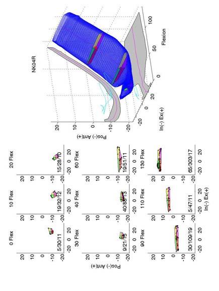
107 94
108 95
109 96
110 97
111 98
112 99
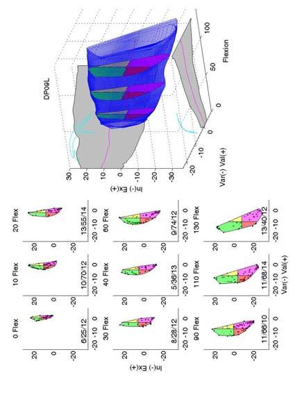
113 100
TOTAL KNEE ARTHROPLASTY (TKA)
") TOTAL KNEE ARTHROPLASTY (TKA) 1 Anatomy, Biomechanics, and Design 2 Femur Medial and lateral condyles Convex, asymmetric Medial larger than lateral 3 Tibia Tibial plateau Medial tibial condyle: concave
TOTAL KNEE ARTHROPLASTY (TKA) 1 Anatomy, Biomechanics, and Design 2 Femur Medial and lateral condyles Convex, asymmetric Medial larger than lateral 3 Tibia Tibial plateau Medial tibial condyle: concave
CONTROL OF THE BOUNDARY CONDITIONS OF A DYNAMIC KNEE SIMULATOR
 CONTROL OF THE BOUNDARY CONDITIONS OF A DYNAMIC KNEE SIMULATOR J. Tiré 1, J. Victor 2, P. De Baets 3 and M.A. Verstraete 2 1 Ghent University, Belgium 2 Ghent University, Department of Physical Medicine
The Knee. Two Joints: Tibiofemoral. Patellofemoral
 Evaluating the Knee The Knee Two Joints: Tibiofemoral Patellofemoral HISTORY Remember the questions from lecture #2? Girth OBSERVATION TibioFemoral Alignment What are the consequences of faulty alignment?
ATTUNE Knee System: Stability in Total Knee Replacement
 ATTUNE Knee System: Stability in Total Knee Replacement Chadd Clary, PhD Staff Engineer DePuy Synthes Joint Reconstruction Young and active total knee replacement (TKR) patients demand a knee that feels
The Effect of Lateral Meniscal Root Injuries on the Stability of the Anterior Cruciate Ligament Deficient Knee
 The Effect of Lateral Meniscal Root Injuries on the Stability of the Anterior Cruciate Ligament Deficient Knee Charles Vega 1, Jebran Haddad 1, Jerry Alexander 2, Jonathan Gold 2, Theodore Shybut 1, Philip
What is Kinesiology? Basic Biomechanics. Mechanics
 What is Kinesiology? The study of movement, but this definition is too broad Brings together anatomy, physiology, physics, geometry and relates them to human movement Lippert pg 3 Basic Biomechanics the
Biomechanics of the Knee. Valerie Nuñez SpR Frimley Park Hospital
 Biomechanics of the Knee Valerie Nuñez SpR Frimley Park Hospital Knee Biomechanics Kinematics Range of Motion Joint Motion Kinetics Knee Stabilisers Joint Forces Axes The Mechanical Stresses to which
Zimmer FuZion Instruments. Surgical Technique (Beta Version)
") Zimmer FuZion Surgical Technique (Beta Version) INTRO Surgical Technique Introduction Surgical goals during total knee arthroplasty (TKA) include establishment of normal leg alignment, secure implant fixation,
Zimmer FuZion Surgical Technique (Beta Version) INTRO Surgical Technique Introduction Surgical goals during total knee arthroplasty (TKA) include establishment of normal leg alignment, secure implant fixation,
Stephen R Smith Northeast Nebraska Orthopaedics PC. Ligament Preserving Techniques in Total Knee Arthroplasty
 Stephen R Smith Northeast Nebraska Orthopaedics PC Ligament Preserving Techniques in Total Knee Arthroplasty 10-15% have Fair to poor Results? Why? The complication rate is 2.567% If It happens To You
ACL Forces and Knee Kinematics Produced by Axial Tibial Compression During a Passive Flexion Extension Cycle
 ACL Forces and Knee Kinematics Produced by Axial Tibial Compression During a Passive Flexion Extension Cycle Keith L. Markolf, Steven R. Jackson, Brock Foster, David R. McAllister Biomechanics Research
Discrepancies in Knee Joint Moments Using Common Anatomical Frames Defined by Different Palpable Landmarks
 Journal of Applied Biomechanics, 2008, 24, 185-190 2008 Human Kinetics, Inc. Discrepancies in Knee Joint Moments Using Common Anatomical Frames Defined by Different Palpable Landmarks Dominic Thewlis,
ACL AND PCL INJURIES OF THE KNEE JOINT
 ACL AND PCL INJURIES OF THE KNEE JOINT Dr.KN Subramanian M.Ch Orth., FRCS (Tr & Orth), CCT Orth(UK) Consultant Orthopaedic Surgeon, Special interest: Orthopaedic Sports Injury, Shoulder and Knee Surgery,
Where Is the Natural Internal-External Rotation Axis of the Tibia?
 Where Is the Natural Internal-External Rotation Axis of the Tibia? Daniel Boguszewski 1, Paul Yang 2, Nirav Joshi 2, Keith Markolf 1, Frank Petrigliano 1, David McAllister 1. 1 University of California
Direct Measurement of Graft Tension in Anatomic Versus Non-anatomic ACL Reconstructions during a Dynamic Pivoting Maneuver
 Direct Measurement of Graft Tension in Anatomic Versus Non-anatomic ACL Reconstructions during a Dynamic Pivoting Maneuver Scott A. Buhler 1, Newton Chan 2, Rikin Patel 2, Sabir K. Ismaily 2, Brian Vial
A Strain-Energy Model of Passive Knee Kinematics for the Study of Surgical Implantation Strategies
 IN:Springer Lecture Notes in Computer Science 1935 A Strain-Energy Model of Passive Knee Kinematics for the Study of Surgical Implantation Strategies E. Chen R. E. Ellis J. T. Bryant Computing and Information
Biomechanical Characterization of a New, Noninvasive Model of Anterior Cruciate Ligament Rupture in the Rat
 Biomechanical Characterization of a New, Noninvasive Model of Anterior Cruciate Ligament Rupture in the Rat Tristan Maerz, MS Eng 1, Michael Kurdziel, MS Eng 1, Abigail Davidson, BS Eng 1, Kevin Baker,
Estimating Total Knee Arthroplasty Joint Loads from Kinematics
 Estimating Total Knee Arthroplasty Joint Loads from Kinematics Clare K. Fitzpatrick, Paul Rullkoetter. University of Denver, Denver, CO, USA. Disclosures: C.K. Fitzpatrick: None. P. Rullkoetter: 5; DePuy
OPEN KNEE: CAPACITY TO REPRODUCE ANTERIOR CRUCIATE LIGAMENT DEFORMATIONS
 OPEN KNEE: CAPACITY TO REPRODUCE ANTERIOR CRUCIATE LIGAMENT DEFORMATIONS A. Erdemir1,2 and S. Sibole3 1. ABSTRACT Simulation-based explorations of the knee have commonly relied on finite element analysis.
Knee Joint Assessment and General View
 Knee Joint Assessment and General View Done by; Mshari S. Alghadier BSc Physical Therapy RHPT 366 m.alghadier@sau.edu.sa http://faculty.sau.edu.sa/m.alghadier/ Functional anatomy The knee is the largest
BIOMECHANICAL MECHANISMS FOR DAMAGE: RETRIEVAL ANALYSIS AND COMPUTATIONAL WEAR PREDICTIONS IN TOTAL KNEE REPLACEMENTS
 Journal of Mechanics in Medicine and Biology Vol. 5, No. 3 (2005) 469 475 c World Scientific Publishing Company BIOMECHANICAL MECHANISMS FOR DAMAGE: RETRIEVAL ANALYSIS AND COMPUTATIONAL WEAR PREDICTIONS
3. Examination of Knee Kinematics In Vitro
 3. Examination of Knee Kinematics In Vitro 3.1 Introduction This chapter details two in vitro studies that were conducted to better understand the kinematic behavior of the knee. First, the role of graft
RN(EC) ENC(C) GNC(C) MN ACNP *** MECHANISM OF INJURY.. MOST IMPORTANT *** - Useful in determining mechanism of injury / overuse
 ENC(C) GNC(C) MN ACNP *** MECHANISM OF INJURY.. MOST IMPORTANT *** - Useful in determining mechanism of injury / overuse") HISTORY *** MECHANISM OF INJURY.. MOST IMPORTANT *** Age of patient Sport / Occupation - Certain conditions are more prevalent in particular age groups (Osgood Schlaters in youth / Degenerative Joint Disease
HISTORY *** MECHANISM OF INJURY.. MOST IMPORTANT *** Age of patient Sport / Occupation - Certain conditions are more prevalent in particular age groups (Osgood Schlaters in youth / Degenerative Joint Disease
Biomechanics of Two Reconstruction Techniques for Elbow Ulnar Collateral Ligament Insufficiency
 Biomechanics of Two Reconstruction Techniques for Elbow Ulnar Collateral Ligament Insufficiency Justin E. Chronister, MD 1, Randal P. Morris, BS 2, Clark R. Andersen, MS 2, J. Michael Bennett, MD 3, Thomas
DYNAMIC ANALYSIS OF THE HUMAN KNEE
 122 Vol. 14 No. 3 June 2002 DYNAMIC ANALYSIS OF THE HUMAN KNEE R. TARLOCHAN,' S. RAMESH,' AND B. M. HILLBERRY 2 ' Department of Mechanical Engineering, University Tenaga Nasional, Selangor, Malaysia. 2Department
ESTIMATION OF ACL FORCES UTILIZING A NOVEL NON-INVASIVE METHODOLOGY THAT REPRODUCES KNEE KINEMATICS BETWEEN SETS OF KNEES. Shon Patrick Darcy
 ESTIMATION OF ACL FORCES UTILIZING A NOVEL NON-INVASIVE METHODOLOGY THAT REPRODUCES KNEE KINEMATICS BETWEEN SETS OF KNEES by Shon Patrick Darcy BS, Walla Walla College, 2000 Submitted to the Graduate Faculty
Ligamentous and Meniscal Injuries: Diagnosis and Management
 Ligamentous and Meniscal Injuries: Diagnosis and Management Daniel K Williams, MD Franciscan Physician Network Orthopedic Specialists September 29, 2017 No Financial Disclosures INTRODUCTION Overview of
Knee Injury Assessment
 Knee Injury Assessment Clinical Anatomy p. 186 Femur Medial condyle Lateral condyle Femoral trochlea Tibia Intercondylar notch Tibial tuberosity Tibial plateau Fibula Fibular head Patella Clinical Anatomy
MCL Injuries: When and How to Repair Scott D. Mair, MD
 MCL Injuries: When and How to Repair Scott D. Mair, MD Professor and Team Physician: Orthopaedic Surgery University of Kentucky School of Medicine Disclosure Institution: Research/Education Smith-Nephew
Knee Movement Coordination Deficits. ICD-9-CM: Sprain of cruciate ligament of knee
 1 Knee Movement Coordination Deficits Anterior Cruciate Ligament ACL Tear ICD-9-CM: 844.2 Sprain of cruciate ligament of knee ACL Insufficiency ICD-9-CM: 717.83 Old disruption of anterior cruciate ligament
JOINT RULER. Surgical Technique For Knee Joint JRReplacement
 JR JOINT RULER Surgical Technique For Knee Joint JRReplacement INTRODUCTION The Joint Ruler * is designed to help reduce the incidence of flexion, extension, and patellofemoral joint problems by allowing
SKELETAL KINEMATICS OF THE ANTERIOR CRUCIATE LIGAMENT DEFICIENT KNEE WITH AND WITHOUT FUNCTIONAL BRACES
 SKELETAL KINEMATICS OF THE ANTERIOR CRUCIATE LIGAMENT DEFICIENT KNEE WITH AND WITHOUT FUNCTIONAL BRACES Dan K. Ramsey 1, Mario Lamontagne, Per F.Wretenberg 3 and Gunnar Németh 1 School of Human Kinetics,
Mako Partial Knee Medial bicompartmental
 Mako Partial Knee Medial bicompartmental Surgical reference guide Mako Robotic-Arm Assisted Surgery Table of contents Implant compatibility.... 3 Pre-operative planning.... 4 Intra-operative planning....
Medical Practice for Sports Injuries and Disorders of the Knee
 Sports-Related Injuries and Disorders Medical Practice for Sports Injuries and Disorders of the Knee JMAJ 48(1): 20 24, 2005 Hirotsugu MURATSU*, Masahiro KUROSAKA**, Tetsuji YAMAMOTO***, and Shinichi YOSHIDA****
Jennifer L. Cook, MD
 Jennifer L. Cook, MD Florida Joint Replacement and Sports Medicine Center 5243 Hanff Lane New Port Richey, FL 34652 Phone: (727)848-4249 Fax: (727) 841-8934 ANTERIOR CRUCIATE LIGAMENT RECONSTRUCTION POST-OPERATIVE
Exam of the Knee and Ankle I HAVE NO FINANCIAL DISCLOSURES RELEVANT TO THIS PRESENTATION
 Exam of the Knee and Ankle I HAVE NO FINANCIAL DISCLOSURES RELEVANT TO THIS PRESENTATION Disclosures I have no relevant financial relationships with the manufacturers of any commercial products and or
Knee Injuries. PSK 4U Mr. S. Kelly North Grenville DHS. Medial Collateral Ligament Sprain
 Knee Injuries PSK 4U Mr. S. Kelly North Grenville DHS Medial Collateral Ligament Sprain Result from either a direct blow from the lateral side in a medial direction or a severe outward twist Greater injury
7/20/14. Patella Instability. Alignment. PF contact areas. Tissue Restraints. Pain. Acute Blunt force trauma Disorders of the Patellafemoral Joint
 Patella Instability Acute Blunt force trauma Disorders of the Patellafemoral Joint Evan G. Meeks, M.D. Orthopaedic Surgery Sports Medicine The University of Texas - Houston Pivoting action Large effusion
Utility of Instrumented Knee Laxity Testing in Diagnosis of Partial Anterior Cruciate Ligament Tears
 Utility of Instrumented Knee Laxity Testing in Diagnosis of Partial Anterior Cruciate Ligament Tears Ata M. Kiapour, Ph.D. 1, Ali Kiapour, Ph.D. 2, Timothy E. Hewett, Ph.D. 3, Vijay K. Goel, Ph.D. 2. 1
Masterclass. Tips and tricks for a successful outcome. E. Verhaven, M. Thaeter. September 15th, 2012, Brussels
 Masterclass Tips and tricks for a successful outcome September 15th, 2012, Brussels E. Verhaven, M. Thaeter Belgium St. Nikolaus-Hospital Orthopaedics & Traumatology Ultimate Goal of TKR Normal alignment
ACL Rehabilitation and Return To Play
 ACL Rehabilitation and Return To Play Seth Gasser, MD Director of Sports Medicine Florida Orthopaedic Institute Introduction Return to Play: the point in recovery from an injury when a person is safely
Mako Partial Knee Patellofemoral
 Mako Partial Knee Patellofemoral Mako Robotic-Arm Assisted Surgery Surgical reference guide Table of contents Implant compatibility.... 3 Pre-operative implant planning... 4 Intra-operative planning....
ACL Athletic Career. ACL Rupture - Warning Features Intensive pain Immediate swelling Locking Feel a Pop Dead leg Cannot continue to play
 FIMS Ambassador Tour to Eastern Europe, 2004 Belgrade, Serbia Montenegro Acute Knee Injuries - Controversies and Challenges Professor KM Chan OBE, JP President of FIMS Belgrade ACL Athletic Career ACL
Introduction to Biomechanical Analysis
 Introduction to Biomechanical Analysis LEARNING OBJECTIVES: At the end of this laboratory exercise the student will be able to: Identify forces used during activities Identify moments used during activities
Anterior Cruciate Ligament Surgery
 Anatomy Anterior Cruciate Ligament Surgery Roger Ostrander, MD Andrews Institute Anatomy Anatomy Function Primary restraint to anterior tibial translation Secondary restraint to internal tibial rotation
TKA Gap Planning. Supporting healthcare professionals
 TKA Gap Planning The NAVIO TKA Gap Planning stage helps you adjust the plan based on gap information between the femur and tibia implants. Supporting healthcare professionals Interactive Views Four interactive
SOFT TISSUE INJURIES OF THE KNEE: Primary Care and Orthopaedic Management
 SOFT TISSUE INJURIES OF THE KNEE: Primary Care and Orthopaedic Management Gauguin Gamboa Australia has always been a nation where emphasis on health and fitness has resulted in an active population engaged
Knee Android Model Reproducing Internal-External Rotation with Screw-Home Movement of the Human Knee
 Journal of Robotics, Networking and Artificial Life, Vol. 3, No. 2 (September 2016), 69-73 Knee Android Model Reproducing Internal-External Rotation with Screw-Home Movement of the Human Knee Daichi Yamauchi,
The ability of isolated and combined ACL reconstruction and/or lateral monoloop tenodesis to restore intact knee laxity in the presence of isolated
 The ability of isolated and combined ACL reconstruction and/or lateral monoloop tenodesis to restore intact knee laxity in the presence of isolated and combined injuries in- vitro. K.C. Lagae, M.D., Antwerp
A Non-CT Based Total Knee Arthroplasty System Featuring Complete Soft-Tissue Balancing
 A Non-CT Based Total Knee Arthroplasty System Featuring Complete Soft-Tissue Balancing Manuela Kunz 1, Matthias Strauss 2, Frank Langlotz 1, Georg Deuretzbacher 2, Wolfgang Rüther 2, and Lutz-Peter Nolte
Lateral knee injuries
 Created as a free resource by Clinical Edge Based on Physio Edge podcast episode 051 with Matt Konopinski Get your free trial of online Physio education at Orthopaedic timeframes Traditionally Orthopaedic
Tensile Forces in Knee Ligaments in Response to Hyperextension
 Tensile Forces in Knee Ligaments in Response to Hyperextension Kei Kimura 1, Hidenori Otsubo 2, Satoshi Yamakawa 1, Toshihiko Yamashita 2, Hiromichi Fujie 1. 1 Tokyo Metropolitan University, hino, Japan,
Evolution. Medial-Pivot Knee System The Bi-Cruciate-Substituting Knee. Key Aspects
 Evolution Medial-Pivot Knee System The Bi-Cruciate-Substituting Knee Key Aspects MicroPort s EVOLUTION Medial-Pivot Knee System was designed to recreate the natural anatomy that is lost during a total
The ADL Force 5 configured for knee testing
 The ADL Force 5 configured for knee testing Description The AMTI Force 5 is a versatile simulator that can be configured for a variety of single and multiaxis tests, such as joint simulation, product testing,
Multiapical Deformities p. 97 Osteotomy Concepts and Frontal Plane Realignment p. 99 Angulation Correction Axis (ACA) p. 99 Bisector Lines p.
 p. 99 Bisector Lines p.") Normal Lower Limb Alignment and Joint Orientation p. 1 Mechanical and Anatomic Bone Axes p. 1 Joint Center Points p. 5 Joint Orientation Lines p. 5 Ankle p. 5 Knee p. 5 Hip p. 8 Joint Orientation Angles
Normal Lower Limb Alignment and Joint Orientation p. 1 Mechanical and Anatomic Bone Axes p. 1 Joint Center Points p. 5 Joint Orientation Lines p. 5 Ankle p. 5 Knee p. 5 Hip p. 8 Joint Orientation Angles
CLASSIFICATION OF MOBILE BEARING KNEE DESIGN: MOBILITY AND CONSTRAINT
 CLASSIFICATION OF MOBILE BEAING KNEE DESIGN: MOBILITY AND CONSTAINT Orthopaedic esearch Laboratories Lutheran Hospital Cleveland Clinic Health System Christine S. Heim, B.Sc. Paul. D. Postak, B.Sc. Nicholas
Constrained Posterior Stabilized (CPS) Surgical Technique
 Surgical Technique") Constrained Posterior Stabilized (CPS) Surgical Technique Constrained Posterior Stabilized (CPS) Surgical Technique INTRO Introduction The Constrained Posterior Stabilized (CPS) articular surfaces can
Constrained Posterior Stabilized (CPS) Surgical Technique Constrained Posterior Stabilized (CPS) Surgical Technique INTRO Introduction The Constrained Posterior Stabilized (CPS) articular surfaces can
BIOMECHANICS AND CONTEXT OF ACUTE KNEE INJURIES. Uwe Kersting MiniModule Idræt Biomekanik 2. Objectives
 BIOMECHANICS AND CONTEXT OF ACUTE KNEE INJURIES Uwe Kersting MiniModule 06 2011 Idræt Biomekanik 2 1 Objectives Know about the static and dynamic organisation of the knee joint (anatomy & function) Be
Tensioning a Soft Tissue ACL Graft
 Tensioning a Soft Tissue ACL Graft By Stephen M. Howell, MD Maury L. Hull, PhD. Sacramento, CA The method of tensioning a soft tissue ACL graft is controversial, because surgeons do not agree on how much
Prevention and Treatment of Injuries. Anatomy. Anatomy. Chapter 20 The Knee Westfield High School Houston, Texas
 Prevention and Treatment of Injuries Chapter 20 The Knee Westfield High School Houston, Texas Anatomy MCL, Medial Collateral Ligament LCL, Lateral Collateral Ligament PCL, Posterior Cruciate Ligament ACL,
A Patient s Guide to Knee Anatomy. Stephanie E. Siegrist, MD, LLC
 A Patient s Guide to Knee Anatomy Hands, shoulders, knees and toes (and elbows and ankles, too!) Most bone and joint conditions have several treatment options. The best treatment for you is based on your
ACL Patient Assessment and Progress Sheet. Patient Sticker
 Patient Sticker Thank you for taking the time to answer these questions which should only take a few minutes. The answers you give are very useful as they will help us assess your progress following your
Rotating Platform. stabilityinmotion
 Rotating Platform stabilityinmotion BRINGING PATENTED TECHNOLOGIES TO A SEAMLESS SYSTEM, FROM PRIMARY THROUGH REVISION The ATTUNE Revision Rotating Platform Knee System is a comprehensive system that is
Muscle-Tendon Mechanics Dr. Ted Milner (KIN 416)
") Muscle-Tendon Mechanics Dr. Ted Milner (KIN 416) Muscle Fiber Geometry Muscle fibers are linked together by collagenous connective tissue. Endomysium surrounds individual fibers, perimysium collects bundles
Muscle-Tendon Mechanics Dr. Ted Milner (KIN 416) Muscle Fiber Geometry Muscle fibers are linked together by collagenous connective tissue. Endomysium surrounds individual fibers, perimysium collects bundles
Distal Cut First Femoral Preparation
 Surgical Technique Distal Cut First Femoral Preparation Primary Total Knee Arthroplasty LEGION Total Knee System Femoral preparation Contents Introduction...3 DCF femoral highlights...4 Preoperative planning...6
Biomechanics of. Knee Replacement. Mujda Hakime, Paul Malcolm
 Biomechanics of Knee Replacement Mujda Hakime, Paul Malcolm 1 Table of contents Knee Anatomy Movements of the Knee Knee conditions leading to knee replacement Materials Alignment and Joint Loading Knee
Anterolateral Ligament. Bradd G. Burkhart, MD Orlando Orthopaedic Center Sports Medicine
 Anterolateral Ligament Bradd G. Burkhart, MD Orlando Orthopaedic Center Sports Medicine What in the world? TIME magazine in November 2013 stated: In an age filled with advanced medical techniques like
Investigating the loading behaviour of intact and meniscectomy knee joints and the impact on surgical decisions
 Investigating the loading behaviour of intact and meniscectomy knee joints and the impact on surgical decisions M. S. Yeoman 1 1. Continuum Blue Limited, One Caspian Point, Caspian Way, CF10 4DQ, United
A Patient s Guide to Knee Anatomy
 A Patient s Guide to Knee Anatomy 15195 Heathcote Blvd Suite 334 Haymarket, VA 20169 Phone: 703-369-9070 Fax: 703-369-9240 DISCLAIMER: The information in this booklet is compiled from a variety of sources.
A Kinematic Assessment of Knee Prosthesis from Fluoroscopy Images
 Memoirs of the Faculty of Engineering, Kyushu University, Vol. 68, No. 1, March 2008 A Kinematic Assessment of Knee Prosthesis from Fluoroscopy Images by Mohammad Abrar HOSSAIN *, Michihiko FUKUNAGA and
Rehabilitation Guidelines for Anterior Cruciate Ligament (ACL) Reconstruction
 Reconstruction") Rehabilitation Guidelines for Anterior Cruciate Ligament (ACL) Reconstruction The knee is the body's largest joint, and the place where the femur, tibia, and patella meet to form a hinge-like joint. These
Rehabilitation Guidelines for Anterior Cruciate Ligament (ACL) Reconstruction The knee is the body's largest joint, and the place where the femur, tibia, and patella meet to form a hinge-like joint. These
Kinematics Analysis of Different Types of Prosthesis in Total Knee Arthroplasty with a Navigation System
 Showa Univ J Med Sci 29 3, 289 296, September 2017 Original Kinematics Analysis of Different Types of Prosthesis in Total Knee Arthroplasty with a Navigation System Hiroshi TAKAGI 1 2, Soshi ASAI 1, Atsushi
Alignment in TKA using a Simulated Oxford Rig. Thesis. Julie Ann Thompson. Graduate Program in Mechanical Engineering. The Ohio State University
 The Biomechanical Effects of Variability in Femoral and Tibial Component Rotational Alignment in TKA using a Simulated Oxford Rig Thesis Presented in Partial Fulfillment of the Requirements for the Degree
Plaster-Wedging Technique:
 Plaster-Wedging Technique: An Appropriate, Safe, Quick, & Economical Method To Stretch Soft Tissue Contractures Of The Knee H.M. Steenbeek General Information. In the field of physical rehabilitation of
5/13/2016. ACL I Risk Factors AAP Position Statement. Anterior Cruciate Ligament Injuries: Diagnosis, Treatment and Prevention.
 ACL I Risk Factors AAP Position Statement Timothy E. Hewett, PhD 2016 Chicago Sports Medicine Symposium Chicago, Illinois August 5-7, 2016 2015 MFMER slide-1 Anterior Cruciate Ligament Injuries: Diagnosis,
Our objectives were to establish the envelope of
 Intraoperative measurement of knee kinematics in reconstruction of the anterior cruciate ligament A. M. J. Bull, P. H. Earnshaw, A. Smith, M. V. Katchburian, A. N. A. Hassan, A. A. Amis From Imperial College,
Research Theme. Cal PT Fund Research Symposium 2015 Christopher Powers. Patellofemoral Pain to Pathology Continuum. Applied Movement System Research
 Evaluation and Treatment of Movement Dysfunction: A Biomechanical Approach Research Theme Christopher M. Powers, PhD, PT, FAPTA Understanding injury mechanisms will lead to the development of more effective
Biomechanical Effects of Femoral Component Axial Rotation in Total Knee Arthroplasty (TKA)
") Biomechanical Effects of Femoral Component Axial Rotation in Total Knee Arthroplasty (TKA) Mohammad Kia, PhD, Timothy Wright, PhD, Michael Cross, MD, David Mayman, MD, Andrew Pearle, MD, Peter Sculco,
Biomechanical Effects of Femoral Component Axial Rotation in Total Knee Arthroplasty (TKA) Mohammad Kia, PhD, Timothy Wright, PhD, Michael Cross, MD, David Mayman, MD, Andrew Pearle, MD, Peter Sculco,
W. Dilworth Cannon, M.D. Professor of Clinical Orthopaedic Surgery University of California San Francisco
 Knee Pain And Injuries In Adults W. Dilworth Cannon, M.D. Professor of Clinical Orthopaedic Surgery University of California San Francisco Pain Control Overview Narcotics rarely necessary after 1 st 1-2
2017 Resident Advanced Trauma Techniques Course COMPLICATIONS / CHALLENGES MALUNIONS/DEFORMITY
 2017 Resident Advanced Trauma Techniques Course COMPLICATIONS / CHALLENGES MALUNIONS/DEFORMITY What is a Malunion? Definition: a fracture that has healed in a nonanatomic (i.e. deformed) position Must
CLINICAL FINDINGS USING THE VERASENSE KNEE SYSTEM THE INTELLIGENT CHOICE FOR FLEXION STABILITY
 CLINICAL FINDINGS USING THE VERASENSE KNEE SYSTEM THE INTELLIGENT CHOICE FOR FLEXION STABILITY TIGHT PCL Unfavorable Clinical Outcomes of an Excessively Tight PCL A tight PCL can result in excessive femoral
On Field Assessment and Management of Acute Knee Injuries: A Physiotherapist s Perspective
 On Field Assessment and Management of Acute Knee Injuries: A Physiotherapist s Perspective Jessica Condliffe Physiotherapist / Clinic Manager TBI Health Wellington Presentation Outline Knee anatomy review
Retrieved from DalSpace, the institutional repository of Dalhousie University
 Retrieved from DalSpace, the institutional repository of Dalhousie University https://dalspace.library.dal.ca/handle/10222/72293 Version: Post-print Publisher s version: Wilson, Janie L. Astephen, Michael
Application of an Intra-operative Load Measuring System for Knee Replacement Surgery
 Application of an Intra-operative Load Measuring System for Knee Replacement Surgery T.V. Skrinskas 1,2, D.G. Viskontas 1,3, L. Ferreira 1, D.G. Chess 1,3, and J.A. Johnson 1,2,3,4 1 Hand and Upper Limb
The Human Machine: Biomechanics in Daily Life.
 The Human Machine: Biomechanics in Daily Life www.fisiokinesiterapia.biz Biomechanics The study or application of mechanics to biological systems. The study of the forces that act on the body and their
An estimated anterior cruciate ligament. Mechanisms of Noncontact Anterior Cruciate Ligament Injury
 Journal of Athletic Training 2008;43(4):396 408 g by the National Athletic Trainers Association, Inc www.nata.org/jat systematic review Mechanisms of Noncontact Anterior Cruciate Ligament Injury Yohei
Massive Varus- Overview. Massive Varus- Classification. Massive Varus- Definition 07/02/14. Correction of Massive Varus Deformity in TKR
 07/02/14 Massive Varus- Overview Correction of Massive Varus Deformity in TKR Myles Coolican Val d Isere 2014 Massive Varus- Classification Classification Intra articular Massive Varus- Classification Classification
Intact and ACL-Deficient Knee MODEL Evaluation
 Abstract The human knee joint has a three dimensional geometry with multiple body articulations that produce complex mechanical responses under loads that occur in everyday life and sports activities.
STIFFNESS AFTER TKA PRE, PER AND POST OPERATIVE CAUSING FACTORS
 STIFFNESS AFTER TKA PRE, PER AND POST OPERATIVE CAUSING FACTORS Patrick DJIAN INTRODUCTION Stiffness is one of the most common complications following TKR, causing frustration to both the surgeon and the
This presentation is the intellectual property of the author. Contact them for permission to reprint and/or distribute.
 43 rd Annual Symposium on Sports Medicine UT Health Science Center San Antonio School of Medicine January 22-23, 2016 Intra-articular / Extra-synovial 38 mm length / 13 mm width Fan-shaped structure narrowest-midportion
Knee Joint Anatomy 101
 Knee Joint Anatomy 101 Bone Basics There are three bones at the knee joint femur, tibia and patella commonly referred to as the thighbone, shinbone and kneecap. The fibula is not typically associated with
Functional Movement Test. Deep Squat
 Functional Movement Test Put simply, the FMS is a ranking and grading system that documents movement patterns that are key to normal function. By screening these patterns, the FMS readily identifies functional
Fixed Bearing. stabilityinmotion
 Fixed Bearing stabilityinmotion BRINGING PATENTED TECHNOLOGIES TO A SEAMLESS SYSTEM, FROM PRIMARY THROUGH TO REVISION The ATTUNE Revision Fixed Bearing Knee System is a comprehensive system that is designed
ANATOMIC. Navigated Surgical Technique 4 in 1 TO.G.GB.016/1.0
 ANATOMIC Navigated Surgical Technique 4 in 1 TO.G.GB.016/1.0 SCREEN LAYOUT Take screenshot Surgical step Dynamic navigation zone Information area and buttons 2 SCREEN LAYOUT Indicates action when yellow
The Knee. Prof. Oluwadiya Kehinde
 The Knee Prof. Oluwadiya Kehinde www.oluwadiya.sitesled.com The Knee: Introduction 3 bones: femur, tibia and patella 2 separate joints: tibiofemoral and patellofemoral. Function: i. Primarily a hinge joint,
Q: What is the relationship between muscle forces and EMG data that we have collected?
 FAQs ABOUT OPENSIM Q: What is the relationship between muscle forces and EMG data that we have collected? A: Muscle models in OpenSim generate force based on three parameters: activation, muscle fiber
Physical Examination of the Knee
 History: Pain Traumatic vs. atraumatic Acute vs Chronic Mechanism of injury Swelling, catching, instability Previous evaluation and treatment General Setup Examine standing, sitting and supine Evaluate
Modeling of human knee joint and finite element analysis of landing impact motion
 ISSN 1746-7659, England, UK Journal of Information and Computing Science Vol. 13, No. 1, 2018, pp.044-048 Modeling of human knee joint and finite element analysis of landing impact motion Bao Chunyu 1,3,Meng
Knee Capsular Disorder. ICD-9-CM: Stiffness in joint of lower leg, not elsewhere classified
 1 Knee Capsular Disorder "Knee Capsulitis" ICD-9-CM: 719.56 Stiffness in joint of lower leg, not elsewhere classified Diagnostic Criteria History: Physical Exam: Stiffness Aching with prolonged weight