Thoracolumbar Solutions. Timberline MPF. Lateral Modular Plate Fixation System. Surgical Technique Guide
|
|
|
- Eugenia Tate
- 6 years ago
- Views:
Transcription


1 Thoracolumbar Solutions Timberline MPF Lateral Modular Plate Fixation System Surgical Technique Guide


2 Timberline MPF Lateral System Surgical Technique Guide A first-of-its-kind, lateral, modular plate fixation device that easily and accurately accommodates varying plate styles, sizes and positioning.
3 Timberline MPF Lateral System Surgical Technique Guide 3 TABLE OF CONTENTS Device Description 4 Preoperative and Intraoperative Preparation 6 Patient Preparation 7 Surgical Approach Preparation and Retraction 8 Surgical Approach Retraction and Discectomy 9 Implant Sizing and Insertion 10 Screw Hole Preparation 1 Screw Insertion 14 Cover Plate Assembly 15 Optional In Situ Implant Assembly 16 Optional Angled Instrumentation 18 Retractor Removal and Closure 1 Appendix A Hyperlordotic Implant Considerations Zimmer Biomet Spine does not practice medicine. Each physician should exercise his or her own independent judgment in the diagnosis and treatment of an individual patient, and this information does not purport to replace the comprehensive training physicians have received. The following general Surgical Technique Guide is for illustrative purposes only. As with all surgical procedures, the technique used in each case will depend on the surgeon s medical judgment as to the best treatment for each patient. Only those individuals with specialized training and experience in spinal surgery should attempt to use the Timberline MPF Lateral Modular Plate Fixation System. Detailed preoperative clinical and diagnostic evaluation followed by carefully executed surgical technique is essential. Refer to the Instructions for Use (IFU) for a complete list of prescribing information. This technique guide was developed in conjunction with health care professionals. Appendix A Implant Sizing and Insertion 3 Appendix A Insertion and Screw Hole Preparation 5 Appendix A Screw Insertion 6 Appendix A Cover Plate Assembly, Retractor Removal and Supplemental Fixation 7 Timberline Implant Sizes and Graft Volumes 8 Implant Design Features 31 Kit Overview 3 Timberline MPF Implant and Instrument Kits 33 Optional Timberline MPF Implant and Instrument Kits 34 Timberline Standard Implant and Instrument Kits 35 Important Information on the Timberline MPF Lateral System 40


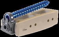
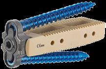
4 4 Timberline MPF Lateral System Surgical Technique Guide DEVICE DESCRIPTION The Timberline MPF Lateral Modular Plate Fixation System is a complete lateral access fusion system, including an intuitive, low-profile modular retractor system, fiber optic lighting, PEEK-OPTIMA LT1 interbody spacers and thoughtfully designed instruments to aid in access and implantation. The system is designed for the treatment of degenerative traumatic and pathologic conditions, and deformities of the thoracic and lumbar spine. System highlights include: Low-profile implant design allows for minimal retractor exposure. Interchangeable plate and interbody spacer options for intraoperative flexibility. 1-, - and 4-screw plate designs. Variable screws (5.5mm with 6.0mm rescue option). 15 of cephalad/caudal angulation to avoid adjacent-level pedicle screws. Plate design limits A/P screw angulation to avoid undesired screw trajectories. Nominal 0 and 5 screw trajectory for optimal cortical bone purchase. Single-step lock plate for screw back out prevention. Simple mayo stand or in situ threaded assembly options. Fixed and variable drill guides to assist in desired screw placement.
5 Timberline MPF Lateral System Surgical Technique Guide 5 Required Equipment ITEMS DETAILS Timberline Implants and Instruments Timberline Case 1, 18mm and mm Implant Kit Timberline Case, Retractor Kit I Timberline Case 3, Retractor Kit II Timberline Case 4, Disc Preparation Kit Timberline Case 5, Rongeur and Implantation Instruments PCR PCR PCR PCR PCR Timberline MPF Implants and Instruments Timberline MPF Implants Kit Timberline MPF Instruments Kit Timberline MPF Hyperlordotic Kit Timberline MPF 14 Implants Kit PCR PCR PCR PCR Timberline Access Kit (single use only) Light Source Radiolucent Breakable Table 300 Watts with an ACMI connection AMSCO 3085 or equivalent Recommended and Optional Equipment ITEMS DETAILS Timberline Monitoring Kit (single use only)* Neuromonitoring Equipment Timberline Auxiliary Instrument Kit Timberline Angled Instrument Kit Timberline System is compatible with any commercially available system Rotating disc cutters, paddle shavers and disc spreaders PCR Recommended for L4 L5 *May not be available in all geographic areas.

6 6 Timberline MPF Lateral System Surgical Technique Guide PREOPERATIVE AND INTRAOPERATIVE PREPARATION NEUROMONITOR STATION C-ARM MONITOR C-ARM LIGHT SOURCE MAYO STAND ANESTHESIA Figure 1 OR layout Preoperative Preparation Review and inspect all instrumentation and implants prior to sterilization. The primary surgeon must be fully experienced with the required spinal fusion techniques, as well as the lateral surgical approach to the spine. Please read the Instructions for Use for a complete list of prescribing instructions. Surgical site access is dependent upon the level and indication(s) being treated. Adequate planning should be done to ensure safe and proper access to the surgical site. Preoperative imaging studies of the anatomy should be examined to: Ensure that the range of implant sizes is appropriate for the patient s anatomy at the proposed operative levels. Give special consideration to L4 L5, ensuring that height of the iliac crest will not prevent access to the L4 L5 disc space. Review anatomy and determine the best approach (i.e., left or right, concave vs. convex side of deformity). Tip: The Timberline Angled Instrument Kit is available upon request. This kit may facilitate access to L4 L5 and other obstructed levels. Confer with the surgeon to ensure you have all of the needed implants (widths, lengths and heights) for the surgery. Intraoperative Preparation All imaging studies should be available for both planning and intraoperative review of the patient s anatomy. The Timberline System may be used alone or, at the surgeon s discretion, in conjunction with a neuromonitoring system. The Timberline Lateral Fusion System may be used with most commercially available neuromonitoring systems. The operative suite should be laid out such that it is conducive to the lateral approach procedure (Figure 1).

7 Timberline MPF Lateral System Surgical Technique Guide 7 PATIENT PREPARATION Neuromonitoring may be selected at the surgeon s discretion. If neuromonitoring is to be used, a neurophysiologist or neuromonitoring technician should apply electrodes to the patient prior to patient positioning. Tip: If neuromonitoring is selected, it is important to discuss with the anesthesiologist that the patient is not to be administered paralytics during the procedure. A train of four test will help ensure an absence of paralytics. STEP 1 Place the patient in a lateral decubitus (90 ) position on a breakable surgical table such that the patient s greater trochanter is directly over the break in the table. The surgical table should be reversed prior to positioning the patient so that fluoroscopy may be used. Tips: Considerations for left- vs. right-side positioning: When anatomy allows, a left-sided approach is preferred. Previous surgeries or anatomical factors may dictate approaching from the patient s right side. Use an axillary roll under the axilla, and a hip bump underneath the patient s greater trochanter. Place pillows under the head, between the knees and under the upper arm. Cover sensitive areas as needed with a towel prior to taping. 3-inch silk surgical tape is recommended. Secure the patient to the table using surgical tape per the following (Figure ): A. Directly across the table, just below the tip of the iliac crest and below table break. B. Directly across the table, over the thoracic region just underneath the arm. C. Just superior and anterior to tip of the iliac crest, down to the foot of the table (posterior), around the corner of the table and back to the tip of the iliac crest. D. Just superior and posterior to tip of the iliac crest, down to the foot of the table (anterior), around the corner of the table and back to the tip of the iliac crest. E. From the tip of the iliac crest, straight down to the end of the table. F. From the anterior edge of the table, over the knee and along the lower leg to the posterior, inferior corner of the table. The pelvis should now be tilted away from the spine by lowering the table s foot end or the patient s legs. Figure Patient positioning and taping
 images may be obtained when the C-arm is set at 90 and 0 respectively.")

8 8 Timberline MPF Lateral System Surgical Technique Guide SURGICAL APPROACH PREPARATION AND RETRACTION Figure 3 Examples of true lateral and A/P images STEP Now that the patient has been secured to the table, adjust the table so that true lateral and anterior-posterior (A/P) images may be obtained when the C-arm is set at 90 and 0 respectively. Note: True A/P orientation of the surgical level has been achieved when the spinous process is centered directly between the pedicles, the pedicles appear round and the endplates are distinguished as a solid line on the A/P radiograph/fluoro. True lateral and A/P images may require adjusting the bed position separately for each level. True lateral orientation is noted by observing a sharp view of the endplates at the operative level and when the neural foramina align perfectly on the lateral radiograph/fluoro (Figure 3).

.")

9 Timberline MPF Lateral System Surgical Technique Guide 9 SURGICAL APPROACH RETRACTION AND DISCECTOMY POSTERIOR HANDLE CRANIAL/CAUDAL HANDLE LOCKING COLLAR RETRACTOR BODY POSTERIOR ARM CRANIAL/CAUDAL ARMS Figure 4a Retractor components Figure 4b Wave guide attachment Figure 4c Monopolar probe insertion STEP 3 The Timberline retractor is utilized to create the desired exposure for implanting the Timberline MPF implant. Refer to the Timberline Surgical Technique Guide for instructions on using the Timberline retractor (Figures 4a, b, c). Tip: The Timberline MPF plate trial may be placed into the working space to verify adequate access has been achieved to allow room for the plate. These are optional instruments and must be ordered separately. STEP 4 Refer to the Timberline Surgical Technique Guide for instructions on performing the discectomy, and for information regarding available Timberline disc preparation instruments.

, and appropriately centered in the anterior/posterior plane. Implant length can be determined using the holes in the trial.")

10 10 Timberline MPF Lateral System Surgical Technique Guide IMPLANT SIZING AND INSERTION 60mm 50mm 40mm Figure 5a Implant trialing Figure 5b Plate trialing Figure 5c Hyperlordotic spacer STEP 5 Use the Timberline implant trials to determine the correct length and height of the interbody implant. Note: Trials for each implant width, lordotic angle and height are provided in the kit. Trial fit should be snug, but not extremely tight. Use caution to avoid over distracting the disc space. Confirm correct placement of the trial using fluoroscopy. The trial should be centered across the disc space (medial/lateral), and appropriately centered in the anterior/posterior plane. Implant length can be determined using the holes in the trial. Holes are placed, 40mm, 50mm and 60mm from the tip of the trial. The slap hammer may be used to assist with removal of spreaders or trials (Figure 5a). Note: Timberline trial heights correlate directly to implant heights to accurately replicate implant fit. Tip: The surgeon should take a lateral fluoroscopic image to verify that the trial is positioned appropriately in the A/P plane. The trial and subsequent implant should be centered in the disc space anterior to posterior. Note: Plate trials are available upon request to confirm plate sizing and adequate exposure if desired (Figure 5b). Note: If using hyperlordotic spacers (Figure 5c), please refer to appendix A on page 3. This appendix will cover ALL resection, hyperlordotic sizing and implant construct placement.

11 Timberline MPF Lateral System Surgical Technique Guide 11 Figure 6 Plate and interbody assembly Figure 7 Inserter attachment STEP 6 Assemble the device by selecting the appropriate size PEEK-OPTIMA interbody and the corresponding plate. Plate options include 1-, - and 4-hole plate configurations as determined by the patient s fixation needs. Assemble the plate and interbody spacer using the kit screw driver and torque limiting handle until it clicks (1in-lb) (Figure 6). Note: The 1-hole plate caddy is available in hyperlordotic or 14 kits or separate. STEP 7 Attach the implant inserter to the implant assembly by threading the draw rod into the center of the plate (Figure 7). The draw rod is advanced by turning the thumb wheel of the inserter. Attach the desired handle to the inserter. Note: If the matching plate size is used, the full variable bone screw cephalad/caudal angulation may be utilized (4-hole plate: 0 15, 1- and -hole plate: 5 0 ). The 4-hole plate may by undersized by up to two sizes and the 1- and -hole plates may be undersized by one size. When undersizing the plate, care must be taken to avoid vertebral endplate damage and to allow proper clearance between the bone screw and PEEK-OPTIMA interbody. When undersizing the 4-hole plate by one size the bone screw should be inserted at a minimum cephalad/caudal angulation of 3 and if undersizing the 4-hole plate by two sizes a minimum cephalad/caudal angulation of 5 should be used. When undersizing the -hole plate by one size the bone screw should be inserted at a minimum cephalad/caudal angulation of 10. Do not oversize the plate.
.")


12 1 Timberline MPF Lateral System Surgical Technique Guide SCREW HOLE PREPARATION Figure 8 Implant insertion Figure 9 Fluoroscopy confirmation Figure 10 Drill guide assembly STEP 8 Impact the implant assembly into the disc space until the plate is resting against the vertebral body (Figure 8). Note: Care should be taken to avoid damaging the vertebral endplates. Confirm correct position using fluoroscopy (Figure 9). STEP 9 Assemble the depth guide onto the fixed or variable drill guide. Depress the button and align the tongue on the depth guide with the groove on the drill guide before advancing to the desired depth (Figure 10). Note: The implant should be centered across the disc space, with the plate resting against the ipsilateral vertebral body and situated near the center of the disc space, anterior to posterior. Ensure that no graft material has extruded out of the implant s graft chamber. Adjust with the implant tamp as necessary.


13 Timberline MPF Lateral System Surgical Technique Guide 13 Figure 11 Awl/drill and guide assembly Figure 1 Awl/drill insertion Figure 13a, b Awl/drill insertion STEP 10 The drills and awls are available in both straight and angled configurations, and the guides are available in both fixed and variable configurations to ensure the appropriate trajectory. Assemble the appropriate combination of the drill or awl and the appropriate guide (fixed or variable) (Figure 11). Place the desired modular handle onto either the awl or drill. Precaution: The use of guides is required to help ensure appropriate screw trajectory. The kit includes both fixed and variable guides. Variable guides allow for cephalad/caudal angulation of the screws. STEP 11 Prepare the screw holes by using either an awl or drill. Place the drill or awl, and guide assembly into the desired screw hole (Figure 1). Ensure the tip of the guide is properly seated in the screw hole of the plate. Advance the awl or drill to the desired depth (Figures 13a, b). Taps are available if desired. Confirm using fluoroscopy. Note: The variable drill guide allows for 15 of angulation in the cephalad or caudal directions only. The fixed drill guide has unique geometry at the tip that creates the fixed screw trajectory of 0 for the 4-hole and 5 for the 1- and -hole when engaged with the plate. Prepare the remaining screw holes using the same technique.
. Note: The Timberline MPF System includes variable screws in 5.")
14 14 Timberline MPF Lateral System Surgical Technique Guide SCREW INSERTION Figure 14 Screw/driver assembly Figure 15 Screw insertion STEP 1 Assemble the desired screw onto the screw driver such that the driver hex is fully seated in the screw. Attach the screw driver to the desired fixed or ratcheting modular handle (Figure 14). Note: The Timberline MPF System includes variable screws in 5.5mm and 6.0mm diameters. Fixed guides can help ensure a good trajectory, but the system does not include fixed screws. STEP 13 Advance the screw into the vertebral body through the appropriate screw hole in the plate following the path previously prepared in the bone (Figure 15). Use fluoroscopy to ensure appropriate screw placement. Insert the remaining screws. Tighten all screws until the screws sit just below the top surface of the plate. Confirm using A/P and lateral fluoroscopy. Tip: For 4-hole plates, a cross-wise screw placement pattern is suggested to optimize plate seating. Note: Use of the integrated screws with interbody spacer angles of 14 and above is mandatory.

. Note: 1-, -, and 4-hole standard cover plates will work for multiple plate sizes within that configuration.")

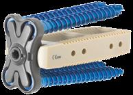
15 Timberline MPF Lateral System Surgical Technique Guide 15 COVER PLATE ASSEMBLY Figure 16 Cover plate Figure 17a Cover plate attachment Figure 17b Final assembly looking down retractor STEP 14 Select the cover plate that corresponds to the plate used. Attach the torque handle to the cover plate driver. Assemble the cover plate onto the cover plate driver by inserting the tip of the cover plate driver into the set screw so that the flanges of the driver align with the slots in the face of the cover plate (Figure 16). Note: 1-, -, and 4-hole standard cover plates will work for multiple plate sizes within that configuration. The size 6 4-hole plate and size 18 1-hole plate have a unique cover plate. The cover plate to be used with the size 6 4-hole plate is marked 6. The size 18 1-hole plate is marked with a black bar in the cover plate recess and is to be paired with the 1-hole large cover plate which contains the same distinguishing marking. STEP 15 Secure the cover plate to the plate by aligning the set screw over the center hole of the plate. Ensure the flanges of the cover plate are aligned so that the cover plate seats into the recess of the plate and the flanges cover the screws. Tighten the cover plate set screw with the torque handle until the torque handle clicks (1in-lb) (Figure 17a). Precaution: Use of the cover plate to prevent screw back-out is mandatory. Inspect final implant for correct position and assembly (Figure 17b).

16 16 Timberline MPF Lateral System Surgical Technique Guide OPTIONAL IN SITU IMPLANT ASSEMBLY Figure 18a Interbody in situ attachment Figure 18b Interbody in situ insertion Figure 19 Optional K-wire insertion STEP 1 The surgeon has the option of inserting the interbody spacer prior to assembly with the plate. This option may be taken in the event that interbody spacer slides are desired for graft containment during insertion. The Timberline MPF inserter is used to insert the interbody spacer into the disc space, leaving the ipsilateral end proud of the disc space (Figures 18a, b). Note: This is the same inserter used when inserting the pre-assembled plate and interbody spacer. Confirm position using fluoroscopy. STEP Optional: If desired, insert a K-wire through the center of the interbody implant until it has passed through the center of the cage and is resting against the contralateral wall of the implant (Figure 19).

.")
.")
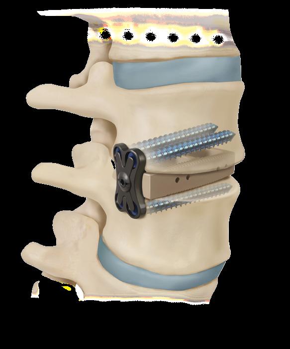
17 Timberline MPF Lateral System Surgical Technique Guide 17 Figure a In situ plate tamp Figure 0 Plate in situ assembly Figure 1 Plate in situ insertion Figure b Intraoperative fluoro image prior to supplemental posterior fixation. Timberline MPF is indicated for use with supplemental posterior fixation. STEP 3 Attach the in situ plate inserter to the plate. Insert the in situ plate inserter into the torque handle (Figure 0). Feed the plate driver assembly and torque handle over the K-wire down onto the interbody implant (Figure 1). Note: The in situ plate inserter and torque handle are cannulated to allow passage over the K-wire. Thread the assembly screw into the interbody spacer and tighten with the torque handle until the handle clicks (1in-lb). STEP 4 Remove the plate driver and K-wire, then utilize the implant tamp to advance the implant assembly until the plate is resting against the vertebral body (Figure a). Confirm correct position using fluoroscopy (Figure b).

18 18 Timberline MPF Lateral System Surgical Technique Guide OPTIONAL ANGLED INSTRUMENTATION Figure 3a Angled instrument inserter assembly Figure 3b Angled insertion STEP 1 Instruments are provided to accommodate working through the retractor when it is positioned on an angle, such as for working at L4 L5, or near the ribs. The following steps outline the technique when use of angled instruments is required. The system includes instruments for both standard assembly and in situ assembly. The Timberline angled disc preparation instruments may be used to perform the discectomy and to prepare the endplates for fusion. Use the Timberline angled implant trials to determine the correct length and height of the intervertebral disc space. STEP For standard assembly, attach the plate to the interbody implant per the standard procedure referenced above (page 11 step 6). Attach the angled plate assembly inserter to the implant assembly (Figure 3a). Impact the implant assembly into the disc space until the plate rests against the ipsilateral edge of the vertebral body (Figure 3b).

. STEP 4 Then advance the awl or drill into the bone to the desired depth (Figure 4b).")
19 Timberline MPF Lateral System Surgical Technique Guide 19 0mm Figure 4a U-joint awl assembly Figure 4b U-joint awl insertion STEP 3 Prepare the screw holes using the u-joint awl or drill and the angled drill guide. Slide the angled drill guide over the tip of the awl or drill, then advance the assembly into the retractor such that the guide first seats in the screw hole of the plate (Figure 4a). STEP 4 Then advance the awl or drill into the bone to the desired depth (Figure 4b). Note: Take care not to advance the awl or drill too far. Full depth insertion is 0mm past the contralateral surface of the plate.
 Figure 5a U-joint screw assembly Figure 6a Angled plate assembly Figure 5b U-joint")


20 0 Timberline MPF Lateral System Surgical Technique Guide OPTIONAL ANGLED INSTRUMENTATION (continued) Figure 5a U-joint screw assembly Figure 6a Angled plate assembly Figure 5b U-joint screw insertion Figure 6b Angled plate insertion STEP 5 Place the appropriate size screw onto the u-joint driver. Then advance the screw through the plate and into the vertebral body (Figure 5a). Note: It is recommended that the screw ring guide be used to help guide the screws into the plate (Figure 5b). STEP 6 Once all of the screws have been inserted and are seated properly, attach the cover plate to the plate using the angled cover plate inserter (Figures 6a, b). Inspect the construct to ensure all screws are seated correctly and the cover plate is securely attached.
21 Timberline MPF Lateral System Surgical Technique Guide 1 RETRACTOR REMOVAL AND CLOSURE STEP 18 Retract the intradiscal shim into the posterior blade using the shim remover/retractor. Remove the scoville retractor and anterior crossbar attachment. Remove all other shims in the cranial/caudal blades. If the cranial/caudal blades were toed, return them to the zero position. Attach the handle assembly to the retractor body if previously detached. Close the retractor. Loosen the black articulating arm knob and disconnect the arm from the retractor by loosening the thumb screw. Carefully remove the retractor while watching to ensure there is no excess bleeding. Remove the light wave guides. STEP 19 The wound is closed using standard techniques. Timberline MPF Lateral Modular Plate Fixation System is intended to be used with supplemental fixation. Surgeons should follow standard surgical techniques for implantation of FDA- cleared supplemental internal spinal fixation. REMOVAL OR REVISION PROCEDURE OF THE TIMBERLINE MPF IMPLANT (if necessary) 1. Attach the cover plate inserter to the cover plate. Disengage the cover plate by turning the cover plate set screw counter-clockwise using the cover plate inserter.. Attach the bone screw driver to the bone screw. Remove the screw by rotating the screwdriver counter-clockwise. Remove each bone screw in the same manner. 3. Attach the Timberline MPF inserter to the implant assembly. 4. Attach slap hammer to the inserter or use a mallet to tap the inserter and implant assembly outward until the implant is removed from disc space.

.")

22 Timberline MPF Lateral System Surgical Technique Guide APPENDIX A HYPERLORDOTIC CONSIDERATIONS Anterior Longitudinal Ligament (ALL) Resection If the surgeon elects to partially or completely release the ALL, follow the steps below: Figure 7 Anterior soft tissue protection Figure 8 ALL incision STEP A1 Utilize a handheld soft tissue retractor to retract soft tissue directly anterior to the ALL by first identifying the ALL, and then carefully advancing the soft tissue retractor anterior to the ALL but posterior to the great vessels. The retractor should extend past the full width of the ALL. With the soft tissue retractor in place, it can be secured to the retractor body with the anterior crossbar (Figure 7). Note: If calcification of the ALL is present, resection should not be attempted in order to mitigate damage to the vessels. If ALL release is not feasible or deemed to be too risky for any reason, proceed with an alternative approach. Tip: Radiolucent soft tissue retractors are provided in the hyperlordotic kit. This instrument has a tantalum marker 5mm from the end of the instrument tip and two additional markers to identify the width of the instrument. This marker may be used to help with appropriate placement of the retractor. With the handheld soft tissue retractor in position to protect the anterior soft tissues, use the cutting instrument under direct visualization to incise the ALL. Fluoroscopy may be used to ensure that the cutting instrument is not advanced farther than the soft tissue retractor (Figure 8). Note: The Zimmer Biomet Ligament Cutter provides a recessed cutting area, which minimizes the chances of any unwanted soft tissue from coming in contact with the cutting surface.


, and appropriately centered anterior to posterior.")
. Note: For complete release of the ALL, subsequent distraction of the disc space may be required.")
23 Timberline MPF Lateral System Surgical Technique Guide 3 APPENDIX A IMPLANT SIZING AND INSERTION 60mm 50mm 40mm Figure 9 Hyperlordotic trial insertion Figure 30a Hyperlordotic Trialing Lateral Fluoroscopy Figure 30b Hyperlordotic Trialing A/P Fluoroscopy STEP A Use the Timberline hyperlordotic implant trials to determine the correct length and height of the interbody implant, starting with the smallest available size. Trials for each implant width, lordotic angle and height are provided in the Timberline hyperlordotic kit (Figure 9). Tip: A slightly anterior-to-posterior initial trajectory when introducing the trial into the disc space may help in preventing anterior migration of the trial. Note: If the hyperlordotic trial instruments are migrating anteriorly during insertion due to the steep angle of lordosis, guide instruments are available to help prevent this migration. Confirm correct placement of the trial using fluoroscopy. The trial should be centered across the disc space (medial/lateral), and appropriately centered anterior to posterior. Implant length can be determined using the holes in the trial. Holes are placed, 40mm, 50mm and 60mm from the tip of the trial. The slap hammer may be used to assist with removal of spreaders or trials (Figures 30a, b). Note: For complete release of the ALL, subsequent distraction of the disc space may be required. In these cases, when full visualization of the ALL is not possible, the cutter is advanced to the visual limits and then removed. A distractor is placed in the disc space and expanded to separate the remaining ligamentous tissue. Note: The standard Timberline trials can also be sequentially inserted by size to help fully release the ALL. Note: When selecting the appropriate implant and configuration, consider the subsequent posterior treatment and supplemental fixation. Based upon bench testing, resection of the ALL may facilitate insertion of the implant for greater sagittal correction when used with supplemental fixation per the indications.
.")

24 4 Timberline MPF Lateral System Surgical Technique Guide APPENDIX A IMPLANT SIZING AND INSERTION (continued) Figure 31 Plate and PEEK spacer assembly Figure 3 Inserter attachment STEP A3 Assemble the device by selecting the appropriate size interbody spacer and plate. Assemble the plate and interbody spacer using the assembly driver and torque limiting handle (Figure 31). In general, the 1-hole plate size should be down-sized by one size when using a 0 spacer and two sizes when using a 30 spacer. Tip: When selecting the plate size, ensure the screw holes will appropriately lie over the vertebral body, such that the screws engage the vertebral body and achieve adequate bone purchase. Note: Each Timberline hyperlordotic spacer can be assembled to any plate size or configuration, giving the surgeon multiple options when selecting the best plate for the given anatomy. Selection of the 1-hole plate in a hyperlordotic procedure may achieve greater lordotic correction by enabling improved endplate contact and compression when using pedicle screws. STEP A4 Attach the implant inserter to the implant assembly by threading the draw rod into the center of the plate (Figure 3). The draw rod is advanced by turning the thumb wheel of the inserter. Attach the desired handle to the inserter.


25 Timberline MPF Lateral System Surgical Technique Guide 5 APPENDIX A INSERTION AND SCREW HOLE PREPARATION Figure 33 Implant insertion Figure 34a Figure 34b STEP A5 Impact the implant assembly into the disc space (Figure 33). Note: Care should be taken to avoid damaging the vertebral endplates. Tip: An initial anterior-to-posterior trajectory may be required to ensure the implant does not migrate anteriorly. Confirm correct positioning using fluoroscopy. Note: The implant should be centered across the disc space with the plate resting against the ipsilateral vertebral body and situated near the center of the disc space anterior to posterior (Figures 34a, b). Ensure that no graft material has extruded out of the implant graft chamber. Adjust with the implant tamp as necessary. Note: Use of the integrated screws with interbody spacer angles of 14 and above is mandatory.
26 6 Timberline MPF Lateral System Surgical Technique Guide APPENDIX A SCREW INSERTION Figure 35a,b Awl/drill insertion Figure 36 Screw/driver assembly STEP A6 Prepare the screw hole by using either an awl or drill. The drills and awls are available in both straight and angled configurations, and the guides are available in both fixed and variable configurations to ensure the appropriate trajectory (Figures 35a, b). Assemble the appropriate combination of drill or awl and guide. Place the desired modular handle onto either the drill or awl. Place the instrument assembly into the single screw hole. Ensure the tip of the guide is properly seated in the screw hole of the plate. Advance the awl or drill to the desired depth. Confirm using fluoroscopy. Taps are available if desired. Attach the appropriate tap to the desired modular handle. Taps are available in straight and angled configurations. Take and review final fluoroscopy images prior to removing the retractor to ensure good implant placement. STEP A7 Assemble the desired screw onto the screw driver. Attach the screw driver to the desired fixed or ratcheting modular handle. Advance the screw into the vertebral body through the single screw hole in the plate following the path previously prepared in the bone. Use fluoroscopy to ensure appropriate screw placement (Figure 36). Tighten the screw until it sits just below the top surface of the plate. Confirm using A/P and lateral fluoroscopy.


27 Timberline MPF Lateral System Surgical Technique Guide 7 APPENDIX A COVER PLATE ASSEMBLY, RETRACTOR REMOVAL, AND SUPPLEMENTAL FIXATION Figure 38 Attached cover plate Figure 39 Cover plate inserter Figure 40 Intraoperative fluoro image prior to supplemental posterior fixation. Timberline MPF is indicated for use with supplemental posterior fixation. STEP A8 Select the cover plate that corresponds to the plate used. Attach the torque handle to the cover plate driver. Assemble the cover plate onto the cover plate driver by inserting the tip of the cover plate driver into the set screw such that the flanges of the driver align with the slots in the face of the cover plate. Secure the cover plate to the plate/cage assembly by aligning the set screw over the center hole of the plate. Ensure the flanges of the cover plate are aligned such that the cover plate seats into the recess of the plate, and the flanges cover the screws. Tighten the cover plate set screw with the torque handle (1 in-lbs). Note: Use of the cover plate to prevent back-out of the screws is mandatory. Note: The 18mm 1-hole plate has a unique cover plate. The 18mm 1-hole plate is marked with a black bar in the cover plate recess and is to be paired with the 1-hole large cover plate which contains the same distinguishing marking. STEP A9 Inspect final implant for correct position and assembly. Compress vertebral bodies on the implant and secure with supplemental fixation.
28 8 Timberline MPF Lateral System Surgical Technique Guide TIMBERLINE IMPLANT SIZES AND GRAFT VOLUMES Standard Sizes 18mm width, 0 lordosis DESCRIPTION HEIGHT cc 18mm 45mm 0 18mm 50mm 0 18mm 55mm 0 18mm 60mm 0 8mm 1mm 8mm 1mm 8mm 1mm 8mm 1mm mm width, 0 lordosis DESCRIPTION HEIGHT cc mm 45mm 0 mm 50mm 0 mm 55mm 0 mm 60mm 0 8mm 1mm 8mm 1mm 8mm 1mm 8mm 1mm mm width, 8 lordosis DESCRIPTION HEIGHT cc 18mm 45mm 8 18mm 50mm 8 18mm 55mm 8 18mm 60mm 8 8mm 1mm 8mm 1mm 8mm 1mm 8mm 1mm mm width, 8 lordosis DESCRIPTION HEIGHT cc mm 45mm 8 mm 50mm 8 mm 55mm 8 mm 60mm 8 8mm 1mm 8mm 1mm 8mm 1mm 8mm 1mm
29 Timberline MPF Lateral System Surgical Technique Guide 9 Hyperlordotic Implant Sizes and Quantities 18mm width, 14 lordosis DESCRIPTION HEIGHT cc QTY 18mm 45mm 14 18mm 50mm 14 18mm 55mm 14 18mm 55mm 14 1mm 16mm 1mm 16mm 1mm 16mm 1mm 16mm mm width, 14 lordosis DESCRIPTION HEIGHT cc QTY mm 45mm 14 mm 50mm 14 mm 55mm 14 mm 60mm 14 1mm 16mm 1mm 16mm 1mm 16mm 1mm 16mm mm width, 0 lordosis DESCRIPTION HEIGHT cc QTY mm 45mm 0 mm 50mm 0 mm 55mm 0 mm 60mm 0 1mm 16mm 18mm 1mm 16mm 18mm 1mm 16mm 18mm 1mm 16mm 18mm mm width, 30 lordosis DESCRIPTION HEIGHT cc QTY mm 45mm 30 mm 50mm 30 mm 55mm 30 mm 60mm 30 16mm 18mm 0mm 16mm 18mm 0mm 16mm 18mm 0mm 16mm 18mm 0mm
30 30 Timberline MPF Lateral System Surgical Technique Guide TIMBERLINE IMPLANT SIZES AND GRAFT VOLUMES (continued) Plates 1-Hole SIZE LENGTH mm mm mm mm mm mm Hole SIZE LENGTH 8 1mm mm mm mm Hole SIZE LENGTH 6 6.5mm mm mm mm mm Cover Plate TYPE PLATE SIZE PAIRING 1-hole hole Tall hole hole hole Short Note: Plates over 16 must use tall cover plate. Screws Self-Tapping Screws SIZE LENGTH Ø5.5mm 30mm Ø5.5mm 35mm Ø5.5mm 40mm Ø5.5mm 45mm Ø5.5mm 50mm Ø5.5mm 55mm Ø5.5mm 60mm Ø6mm 30mm Ø6mm 35mm Ø6mm 40mm Ø6mm 45mm Ø6mm 50mm Ø6mm 55mm Ø6mm 60mm Bi-Cortical Screws SIZE LENGTH Ø5.5mm 45mm Ø5.5mm 50mm Ø5.5mm 55mm Ø5.5mm 60mm Ø6mm 45mm Ø6mm 50mm Ø6mm 55mm Ø6mm 60mm


31 Timberline MPF Lateral System Surgical Technique Guide 31 IMPLANT DESIGN FEATURES LENGTH 1.6 WIDTH 13. LENGTH.5 M5 3. HEIGHT HEIGHT Note: Height is taken from the anterior portion of the implant on non-parallel implants FLANGE 4-HOLE: 10MM HEIGHT -HOLE: 7.5MM LENGTH HEIGHT LENGTH Note: Cage length is measured to the inside edge of the plate WIDTH Lordotic Options Note: Any plate style may be assembled to the hyperlordotic spacers. The tantalum marker nearest the plate assembly side will align with the tip of the plate set screw when the plate is assembled properly.
32 3 Timberline MPF Lateral System Surgical Technique Guide KIT OVERVIEW Timberline MPF Implant and Instrument Kits DESCRIPTION KIT NUMBER Timberline MPF Implants PCR Timberline MPF Instruments PCR Timberline MPF Hyperlordotic Implants and Instruments PCR Timberline MPF 14 Implants PCR Note: Both MPF kits (implants and instruments) must be ordered to support a hyperlordotic implant and 14 implant surgery. Standard Implant and Instrument Kits Optional Implant and Instrument Kits DESCRIPTION Timberline MPF Case 1, 18mm and mm Implant Kit Timberline Case, Retractor Kit I Timberline Case 3, Retractor Kit II Timberline Case 4, Disc Preparation Kit Timberline Case 5, Rongeur and Implantation Instruments Timberline Access Kit Timberline Monitoring Kit* Special Order MEP Electrode Kit Timberline MPF 1-hole Plate Caddy Timberline Case 6, Auxiliary Instruments Timberline Case 7, Angled Instruments KIT NUMBER PCR PCR PCR PCR PCR PCR PCR PCR *May not be available in all geographic areas.


33 Timberline MPF Lateral System Surgical Technique Guide 33 TIMBERLINE MPF IMPLANT AND INSTRUMENT KITS Timberline MPF Case 1: Implants, Kit Number: PCR Screw Caddy Plate Caddy mm Implant Caddy mm Implant Caddy
 -Hole Plate Trial 8mm 863-008 863-010 1mm 863-01 863-014 4-Hole Plate Trial 8mm 863-0408 863-0410 1mm 863-041 863-0414 Angled -Hole Plate")
34 34 Timberline MPF Lateral System Surgical Technique Guide OPTIONAL TIMBERLINE MPF IMPLANT AND INSTRUMENT KITS Optional 1-hole Plate Caddy, PCR (must be ordered separately) 1-Hole Plate Caddy Optional Plate Trials (must be ordered separately) -Hole Plate Trial 8mm mm Hole Plate Trial 8mm mm Angled -Hole Plate Trial 8mm mm Angled 4-Hole Plate Trial 8mm mm
35 Timberline MPF Lateral System Surgical Technique Guide 35 TIMBERLINE MPF STANDARD IMPLANT AND INSTRUMENT KITS Timberline MPF Case : Instruments, Kit Number: PCR Awl U-Joint Retractable Awl Point Beveled Drill U-Joint Retractable Straight Drill Tap U-Joint Straight Tap, 5.5mm Variable Angled Guide Retractable Sleeve Depth Guide Fixed Angled Guide Variable Retractable Sleeve Angled Driver Guide Fixed Retractable Sleeve Driver U-Joint Driver Straight Split Tip or


36 36 Timberline MPF Lateral System Surgical Technique Guide TIMBERLINE MPF STANDARD IMPLANT AND INSTRUMENT KITS (continued) Timberline MPF Case : Instruments, Kit Number: PCR T-Handle Non-Ratchet ¼ Hex Axial Ratchet Hudson T-Handle Ratchet Hudson Torque Limiting T-Handle Hudson Axial Torque Limiting
37 Timberline MPF Lateral System Surgical Technique Guide 37 Timberline MPF Case : Instruments, Kit Number: PCR (continued) Assembly Driver Straight Tamp K-wire Dispenser Straight Cover Plate Inserter Interbody Removal Tool Interbody Angled Inserter Interbody Straight Inserter Angled Cover Plate Inserter Straight Draw Rod Angled In Situ Plate Inserter Straight In Situ Plate Inserter Angled Tamp


38 38 Timberline MPF Lateral System Surgical Technique Guide TIMBERLINE MPF HYPERLORDOTIC IMPLANTS AND INSTRUMENTS, KIT NUMBER: PCR Ligament Cutter Caddy Ligament Distractor Soft Tissue Retractor Grooved Insulated Caddy Trial Trial, 0, 1mm Trial, 0, Trial, 0, 16mm Trial, 0, 18mm Trial, 30, Trial, 30, 16mm Trial, 30, 18mm Trial, 30, 0mm One-hole Plus Caddy Guides Inserter Guide Fixed Inserter Guide


39 Timberline MPF Lateral System Surgical Technique Guide 39 TIMBERLINE MPF 14 IMPLANT KIT, KIT NUMBER: PCR Trial DESCRIPTION (HEIGHT WIDTH ANGLE) 18mm mm 18mm mm mm 18mm mm mm mm mm mm mm One-hole Plus Caddy mm 14 Implant Caddy mm 14 Implant Caddy
40 40 Timberline MPF Lateral System Surgical Technique Guide IMPORTANT INFORMATION ON THE TIMBERLINE MPF LATERAL MODULAR PLATE FIXATION SYSTEM TRIAL IMAGES Purpose The Timberline MPF System is a lumbar intervertebral body fusion device which is part of the Zimmer Biomet Spinal Fusion System. Device Description The Timberline MPF device is an intervertebral body fusion device consisting of a PEEK-OPTIMA polymer intervertebral spacer, titanium plate and screws. The interbody spacer has a generally rounded shape with various heights and footprints and has a hollowed out central area to accommodate autogenous bone graft. The upper and lower surfaces have a series of transverse grooves formed to improve stability and fixation once the device is inserted. The titanium plate has holes for receiving bone screws and a central hole for receiving a cover plate to prevent screw back-out. The Timberline MPF System is available in a variety of sizes and configurations to approximate anatomical variation in different vertebral levels and/or patient anatomy. The Timberline MPF System is provided non-sterile. Indications for Use When used as a lumbar intervertebral body fusion device, the Timberline MPF System is intended for spinal fusion procedures to be used with autogenous bone graft in skeletally mature patients with degenerative disc disease (DDD) at one or two contiguous spinal levels from L S1. DDD is defined as discogenic back pain with degeneration of the disc confirmed by history and radiographic studies. These patients should have had six months of nonoperative treatment. These DDD patients may have had a previous non-fusion spinal surgery at the involved spinal level(s), and may have up to Grade 1 spondylolisthesis or retrolisthesis at the involved level(s). Implants with 14 lordosis or greater are only indicated from levels L L5 and are to be used with at least one integrated fixation screw. The Timberline MPF implants are to be used with supplemental fixation. Approved supplemental fixation systems include the Zimmer Biomet Spinal Fixation System. Contraindications Contraindications may be relative or absolute. The choice of a particular device must be carefully weighed against the patient s overall evaluation. Circumstances listed below may reduce the chance of a successful outcome. Contraindications include, but are not limited to: Allergy to PEEK, titanium or cobalt chrome alloys, or foreign body sensitivity. Where material sensitivity is suspected, appropriate tests should be made prior to implantation. Known or suspected infection/immune system incompetence. Acute or chronic infectious diseases of any etiology or localization. Any abnormality present which affects the normal process of bone remodeling including, but not limited to, severe osteoporosis involving the spine, bone absorption, osteopenia, active infection at the site or certain metabolic disorders affecting osteogenesis. Morbid Obesity. An overweight or obese patient can produce loads on the spinal system, which can lead to failure of the fixation of the device or failure of the device itself. Any neuromuscular deficit which places an unusually heavy load on the device during the healing period. Open Wounds. Pregnancy. Any other medical or surgical condition which would preclude the potential benefit of spinal surgery, such as the presence of congenital abnormalities, elevation of sedimentation rate unexplained by other diseases, elevation of the white blood count (WBC) or a marked left shift in the WBC differential count. Any case requiring the mixing of components from two different systems. Any case requiring the mixture of stainless steel with titanium, or stainless steel with cobalt chrome implant components. Fever or leukocytosis. Signs of local infection or inflammation. Previous history of infection. Prior fusion at the level to be treated. Alcoholism or heavy smoking. Senility, mental illness or substance abuse, of a severity that the patient may ignore certain necessary limitations and precautions in the use of the implant, leading to failure or other complications. Any patient unwilling to follow postoperative instructions. Inadequate tissue coverage over the operative site.
41 Timberline MPF Lateral System Surgical Technique Guide 41 Possible Complications Possible complications specific to the device may include: Early or late implant bending, breakage, failure, loosening or movement/migration. Bone fracture. Allergic reaction to implant material. Other general complications associated with any spinal surgical procedure may include: Non-union or delayed union, pseudoarthrosis; pain; second surgery; bleeding; infection, early and late; tissue or nerve damage, including dural tears or other neurological problems; incisional complications; scar formation; damage to blood vessels and cardiovascular system compromise; changes in mental status; damage to internal organs and connective tissue; complications due to the use of bone grafting, including graft donor site complications; respiratory problems; reactions to anesthesia and/or death. Warnings Patients with previous spinal surgery at the levels to be treated may have different clinical outcomes compared to those without a previous surgery. The risk of a device expulsion and migration is higher without the use of integrated fixation screws or supplemental fixation. Precautions The Timberline MPF implants are for single use only. Never reuse any implant even if it appears unmarked or undamaged. Reuse of the implant components may result in reduced mechanical performance, malfunction, or failure of the device. Any implant implanted and then removed must be discarded. Use only new implants for each case. Only experienced spinal surgeons should perform the implantation of this system with specific training in the use of vertebral implants. The surgical procedure is technically demanding and presents a risk of serious injury to the patient. The Timberline MPF System is intended to be used only by surgeons specialized in spinal surgery and having thorough knowledge of vertebral anatomy, regional vertebral morphology and the biomechanical principles of the spine. It is advised that the surgeon also be thoroughly familiar with the surgical techniques relative to the use of the device. Based on the fatigue testing results, the physician/surgeon must consider the levels of implantation, patient weight, patient activity level, other patient conditions, etc., which may impact on the performance of the system. Risks associated with neurosurgery, general surgery, orthopedic surgery and the use of general anesthesia should be explained to the patient prior to surgery. It is recommended that the advantages and disadvantages of using implants, as well as alternative treatment methods, are explained to the patient. Preoperatively: The surgeon must be fully conversant with all aspects of the surgical technique and know the indications and contraindications of this type of implant. The surgeon must have acquainted himself before the operation with the specific technique for insertion of the product, which is available from the manufacturer. As part of the preoperative examination, the surgeon must check that no biological, biomechanical or other factors will affect the correct conduct of the operation and the postoperative period. An appropriate range of implant sizes must be available at the time of the operation. Intraoperatively: The correct selection of the type and size of implant appropriate to the patient and the positioning of the implant are extremely important. Postoperatively: Patients must be informed of the precautions to be taken in their everyday life to guarantee a maximum implant service life. It is recommended that regular postoperative follow-up is undertaken to detect early signs of failure of the implants and to consider the action to be taken. Deterioration of the device after bone consolidation cannot be considered to constitute a dysfunction or deterioration in the characteristics of the implants. The use of guides is required to help ensure appropriate screw trajectory. Correct selection and placement of the implants is extremely important. Implant selection must be based upon the bone defect to be treated as well as the patient s weight, height, occupation or degree of physical activity. When using the soft tissue retractor, care must be taken to ensure it is correctly and safely placed. Proper handling of the implant before and during the operation is crucial. Use of the cover plate to prevent back-out of the screws is mandatory. Use of the integrated screws with lordotic angles of 14 and above is mandatory. If a cover plate is disassembled from a plate, it must be discarded and not reused. If a plate is disassembled from an interbody spacer, it must be discarded and not reused. The Timberline MPF device must not be used with vertebral components or instruments from other manufacturers.
nvt Transforaminal Lumbar Interbody Fusion System
 nvt Transforaminal Lumbar Interbody Fusion System 1 IMPORTANT INFORMATION FOR PHYSICIANS, SURGEONS, AND/OR STAFF The nv a, nv p, and nv t are an intervertebral body fusion device used in the lumbar spine
nvp Posterior Lumbar Interbody Fusion System
 nvp Posterior Lumbar Interbody Fusion System 1 IMPORTANT INFORMATION FOR PHYSICIANS, SURGEONS, AND/OR STAFF The nv a, nv p, and nv t are an intervertebral body fusion device used in the lumbar spine following
nva Anterior Lumbar Interbody Fusion System
 nva Anterior Lumbar Interbody Fusion System 1 IMPORTANT INFORMATION FOR PHYSICIANS, SURGEONS, AND/OR STAFF The nv a, nv p, and nv t are an intervertebral body fusion device used in the lumbar spine following
Cervical Solutions. Alta. ACDF System. Surgical Technique Guide
 Cervical Solutions Alta ACDF System Surgical Technique Guide 2 Alta ACDF System Surgical Technique Guide A comprehensive system to address a continuum of fixation requirements and anatomic demands. Alta
EXACTECH SPINE. Operative Technique. Cervical Spacer System. Surgeon focused. Patient driven. TM
 EXACTECH SPINE Operative Technique Cervical Spacer System Surgeon focused. Patient driven. TM ACAPELLA ONE Acapella One Cervical Spacer System is an anterior cervical discectomy and fusion device with
Solitaire Anterior Spinal System
 Surgical Technique Solitaire Anterior Spinal System Independent Stabilization for the Anterior Column Available in Titanium and Contents Introduction... Page 1 Design Features... Page 2 Instruments...
TABLE OF CONTENTS. Vault C Anterior Cervical Discectomy 2 and Fusion (ACDF) System Overview. Implants 3. Instruments 5. Surgical Technique 10
 System Overview. Implants 3. Instruments 5. Surgical Technique 10") Surgical Technique TABLE OF CONTENTS Vault C Anterior Cervical Discectomy 2 and Fusion (ACDF) System Overview Indications 2 Implants 3 Instruments 5 Surgical Technique 10 1. Preoperative planning 10 2.
Surgical Technique TABLE OF CONTENTS Vault C Anterior Cervical Discectomy 2 and Fusion (ACDF) System Overview Indications 2 Implants 3 Instruments 5 Surgical Technique 10 1. Preoperative planning 10 2.
Cervical Spacer System surgical technique
 Blackhawk TM Cervical Spacer System surgical technique Blackhawk TM The BLACKHAWK Cervical Spacer System is designed to provide biomechanical stabilization as an adjunct to fusion. Spinal fixation should
Advantage ALIF. Keith Shevlin Managing Director
 Advantage ALIF Unit 10, 9-11 Myrtle Street, Crows Nest NSW 2065 Keith Shevlin Managing Director keithshevlin@precisionsurgical.com.au Advantage ALIF Introduction & Indications for Use 1 Surgical Technique
Alamo T Transforaminal Lumbar Interbody System Surgical Technique
 Transforaminal Lumbar Interbody System Surgical Technique Table of Contents Indications and Device Description.............. 1 Alamo T Implant Features and Instruments...........2 Surgical Technique......................
Posterior Lumbar Interbody Fusion System
 Px Posterior Lumbar Interbody Fusion System Px PEEK INTERBODY FUSION SYSTEM INDICATIONS FOR USE The Innovasis Px PEEK IBF System is an intervertebral body fusion device for use in patients with degenerative
A U X I L I A R Y C O N N E C T O R S Surgical Technique
 A U X I L I A R Y C O N N E C T O R S Surgical Technique AUXILIARY CONNECTORS ISSYS LP Auxiliary Connectors The ISSYS LP auxiliary connectors were designed to provide medial-lateral variability for the
Table of Contents.
 surgical technique The Ambassador TM Anterior Cervical Plate System is a versatile system of implants and instruments with a variety of sizes to provide optimal anatomic compatibility. The integrated cam
Imola Lateral IBF System Surgical Technique
 Imola Lateral IBF System Surgical Technique IMOLA CIRCUIT TABLE OF CONTENTS Design Rationale Instructions for Use Surgical Technique 1. Table Mounting 2. Surgical Planning & Targeting 3. Access and Preparation
TABLE OF CONTENTS. ShurFit Anterior Cervical Interbody Fusion (ACIF) System Overview 2. Implant Specifications 3. Instrument Features 4
 System Overview 2. Implant Specifications 3. Instrument Features 4") Surgical Technique TABLE OF CONTENTS ShurFit Anterior Cervical Interbody Fusion (ACIF) System Overview 2 Product Highlights 2 Indications 2 Implant Specifications 3 Instrument Features 4 Surgical Technique
Surgical Technique TABLE OF CONTENTS ShurFit Anterior Cervical Interbody Fusion (ACIF) System Overview 2 Product Highlights 2 Indications 2 Implant Specifications 3 Instrument Features 4 Surgical Technique
PILLAR AL. Anterior Lumbar Interbody Fusion (ALIF) and Partial Vertebral Body Replacement (pvbr) PEEK Spacer System OPERATIVE TECHNIQUE
 and Partial Vertebral Body Replacement (pvbr) PEEK Spacer System OPERATIVE TECHNIQUE") PILLAR AL PEEK Spacer System Anterior Lumbar Interbody Fusion (ALIF) and Partial Vertebral Body Replacement (pvbr) OPERATIVE TECHNIQUE Table of Contents 1 INTRODUCTION 2 PRE-OPERATIVE TECHNIQUE 3 OPERATIVE
PILLAR AL PEEK Spacer System Anterior Lumbar Interbody Fusion (ALIF) and Partial Vertebral Body Replacement (pvbr) OPERATIVE TECHNIQUE Table of Contents 1 INTRODUCTION 2 PRE-OPERATIVE TECHNIQUE 3 OPERATIVE
Thoracolumbar Solutions. Timberline. Lateral Fusion System. Surgical Technique Guide
 Thoracolumbar Solutions Timberline Lateral Fusion System Surgical Technique Guide 2 Timberline Lateral Fusion System Surgical Technique A complete and comprehensive minimally invasive lateral system consisting
Veyron -C Anterior Cervical System Surgical Technique
 Veyron -C Anterior Cervical System Surgical Technique 2 Veyron-C Anterior Cervical System Surgical Technique Veyron-C Anterior Cervical System Surgical Technique Description, Indications & Contraindications...3
HawkeyeTM Peek. surgical technique
 HawkeyeTM Peek surgical technique Introduction The ChoiceSpine HAWKEYE Vertebral Body Replacement (VBR) System is intended for use in the thoracolumbar spine (T1 - L5) to replace a collapsed, damaged,
Alamo C. Cervical Interbody System Surgical Technique. An Alliance Partners Company
 Cervical Interbody System Surgical Technique Table of Contents Indications for Use................................1 Device Description............................... 1 Alamo C Instruments..............................
Cervical Solutions. Optio-C Anterior Cervical PEEK. Interbody System. Surgical Technique Guide
 Cervical Solutions Optio-C Anterior Cervical PEEK Interbody System Surgical Technique Guide 2 Optio-C Anterior Cervical PEEK Interbody System Surgical Technique Guide The Optio-C System provides a zero-profile
Zimmer Anterior Buttress Plate System. Surgical Technique
 Zimmer Anterior Buttress Plate System Surgical Technique 2 Zimmer Anterior Buttress Plate System Surgical Technique Zimmer Anterior Buttress Plate System Surgical Technique Description, Indications & Contraindications...
ACP1 CERVICAL PLATE SPINAL SYSTEM SURGICAL TECHNIQUE GUIDE II.
 I. ACP1 CERVICAL PLATE II. SPINAL SYSTEM SURGICAL TECHNIQUE GUIDE I. Introduction The Gold Standard Orthopaedics, LLC ACP1 Spinal System was designed with surgeons to incorporate strength, functionality,
CROSS -FUSE P E E K V B R / I B F SYST E M
 S U R G I C A L T E C H N I Q U E CROSS -FUSE P E E K V B R / I B F SYST E M S U R G I C A L S Y S T E M O V E R V I E W 2 CROSS-FUSE P E E K V B R / I B F S Y S T E M S U R G I C A L T E C H N I Q U E
Y o u r Id e a s En g i n e e r e d t o Li f e
 ISSYS LP Spinal Fixation System Surgical Guide Y o u r Id e a s En g i n e e r e d t o Li f e In t r o d u c t i o n ISSYS LP Sp i n a l Fixation System The foundation of the ISSYS LP Spinal Fixation System
MODULAR DESIGN OFFERS FREEDOM OF CHOICE. Surgical Technique
 MODULAR DESIGN OFFERS FREEDOM OF CHOICE Surgical Technique Joint Spine Sports Med MectaLIF Anterior Surgical Technique 2 INDEX 1. INTRODUCTION 4 1.1 Material & Marker 5 2. INDICATIONS 5 3. CONTRAINDICATIONS
SURGICAL TECHNIQUE MANUAL. InterFuse T
 1 CONTENTS InterFuse T Product Description 3 Indications for Use 3 X-Ray Marker Locations 4 Product Specifications 4 Instrument Set 5 Step 1 Preoperative Planning 8 Patient Positioning 8 Step 2 Disc Removal
SURGICAL TECHNIQUE GUIDE TRESTLE. Anterior Cervical Plating System
 SURGICAL TECHNIQUE GUIDE TRESTLE Anterior Cervical Plating System 2 SURGICAL TECHNIQUE GUIDE SURGICAL TECHNIQUE GUIDE System Features Large window enables visualization of graft site and end plates Screw
Cervical Solutions. Optio-C Anterior Cervical Plate. with Allograft/Autograft. Surgical Technique Guide
 Cervical Solutions Optio-C Anterior Cervical Plate with Allograft/Autograft Surgical Technique Guide 2 Optio-C Anterior Cervical Plate with Allograft/Autograft Surgical Technique Guide The Optio-C System
Royal Oak IBFD System Surgical Technique Posterior Lumbar Interbody Fusion (PLIF)
") Royal Oak IBFD System Surgical Technique Posterior Lumbar Interbody Fusion (PLIF) Preoperative Planning Preoperative planning is necessary for the correct selection of lumbar interbody fusion devices.
Royal Oak IBFD System Surgical Technique Posterior Lumbar Interbody Fusion (PLIF) Preoperative Planning Preoperative planning is necessary for the correct selection of lumbar interbody fusion devices.
TM TM Surgical Technique
 TM TM Surgical Technique TABLE OF CONTENTS Reli SP Spinous Plating System Overview Device Description Implant Features Indications Instruments Access Instruments Preparation Instruments Insertion Instruments
product overview Implant heights range from 8mm-20mm in 2mm increments, with two lordocic angle options of 6 and 12.
 ETHOS A-Spacer PEEK System Surgical Technique Guide Synchronizing Medical Innovation with Global Markets product overview The SyncMedical Ethos PEEK IBF System is an intervertebral body fusion device for
Apache Cervical Interbody Fusion Device. Surgical Technique. Page of 13. LC-005 Rev F
 LC-005 Rev F Apache Cervical Interbody Fusion Device Page of 13 Surgical Technique INDICATIONS: When used as an intervertebral body fusion device, the Genesys Spine Interbody Fusion System is indicated
C-THRU Anterior Spinal System
 C-THRU Anterior Spinal System Surgical Technique Manufactured From Contents Introduction... Page 1 Design Features... Page 2 Instruments... Page 3 Surgical Technique... Page 4 Product Information... Page
BAK/C Cervical Anterior Interbody Fusion System
 Surgical Technique BAK/C Cervical Anterior Interbody Fusion System The Comfortable Choice for Cervical Fusion BAK/C Cervical Surgical Technique 1 The BAK/C Cervical Fusion System is an alternative to conventional
OPERATIVE TECHNIQUE. CONSTRUX Mini PTC. Mini PTC Spacer System
 OPERATIVE TECHNIQUE CONSTRUX Mini PTC Mini PTC Spacer System TABLE OF CONTENTS Introduction 1 Operative Technique 2 Part Numbers 6 Indications For Use 7 INTRODUCTION 1 INTRODUCTION The CONSTRUX Mini PTC
OPERATIVE TECHNIQUE COVER IMAGE OPTIONAL (DETAIL) IMAGE SKYHAWK. lateral interbody fusion system lateral plate system
 IMAGE SKYHAWK. lateral interbody fusion system lateral plate system") OPERATIVE TECHNIQUE COVER IMAGE OPTIONAL (DETAIL) IMAGE SKYHAWK lateral interbody fusion system lateral plate system TABLE OF CONTENTS Introduction 1 Pre-Operative Technique 2 Operative Technique 3 Part
OPERATIVE TECHNIQUE COVER IMAGE OPTIONAL (DETAIL) IMAGE SKYHAWK lateral interbody fusion system lateral plate system TABLE OF CONTENTS Introduction 1 Pre-Operative Technique 2 Operative Technique 3 Part
Royal Oak Cervical Plate System
 Royal Oak Cervical Plate System Manufactured by Nexxt Spine, Inc. Royal Oak Cervical Plate System INTRODUCTION FEATURES AND BENEFITS Table of Contents SURGICAL TECHNIQUE Step 1. Patient Positioning Step
100 Interpace Parkway Parsippany, NJ
 100 Interpace Parkway Parsippany, NJ 07054 www.biometspine.com 800-526-2579 All trademarks are the property of Biomet, Inc. or one of its subsidiaries, unless otherwise indicated. Rx Only. 2009 EBI, LLC.
VTI INTERFUSE T SURGICAL TECHNIQUE FORWARD THINKING FOR THE BACK. 1/20
 VTI INTERFUSE T SURGICAL TECHNIQUE FORWARD THINKING FOR THE BACK. 1/20 CONTENTS InterFuse T Product Description Indications for Use X-Ray Marker Locations Product Specifications Instrument Set 3 4 5 STEP
XRL A modular expandable radiolucent vertebral body replacement system
 XRL A modular expandable radiolucent vertebral body replacement system This publication is not intended for distribution in the USA. SURGICAL TECHNIQUE Table of Contents Introduction XRL 2 AO Spine Principles
VTI INTERFUSE S SURGICAL TECHNIQUE FORWARD THINKING FOR THE BACK.
 VTI INTERFUSE S SURGICAL TECHNIQUE FORWARD THINKING FOR THE BACK. CONTENTS InterFuse S Product Description Indications for Use X-Ray Marker Locations and Product Specifications Instrument Set 3 4 5-7 STEP
Thoracolumbar Solutions. Zyston Curve. Interbody Spacer System. Surgical Technique Guide
 Thoracolumbar Solutions Zyston Curve Interbody Spacer System Surgical Technique Guide 2 Zyston Curve Interbody Spacer System Surgical Technique Guide The Zyston Curve Interbody System is designed to optimize
Surgical Technique. Apache Anterior Lumbar Interbody Fusion
 Surgical Technique Apache Anterior Lumbar Interbody Fusion 2 Table of Contents Page Preoperative Planning 4 Patient Positioning 4 Disc and Endplate Preparation 4 Distraction/Size Selection 5 Implantation
ACP. Anterior Cervical Plate System SURGICAL TECHNIQUE
 ACP Anterior Cervical Plate System SURGICAL TECHNIQUE ACP TABLE OF CONTENTS INTRODUCTION 4 INDICATIONS AND CONTRAINDICATIONS 5 WARNINGS AND PRECAUTIONS 6 IMPLANT DESCRIPTION 7 INSTRUMENTS 10 SURGICAL
SYNFIX EVOLUTION SECURED SPACER SYSTEM
 SYNFIX EVOLUTION SECURED SPACER SYSTEM Instruments and implants for stand-alone anterior lumbar interbody fusion Instruments and implants approved by the AO Foundation. This publication is not intended
Thunderbolt. surgical technique. MIS Pedicle Screw System. Where Nimble and Secure Intersect
 Thunderbolt TM MIS Pedicle Screw System Where Nimble and Secure Intersect surgical technique i www.choicespine.com System Features Dovetail set screw: Minimizes head splay and cross-threading Secure connection
Surgical Technique Manual
 InterFuse S Interbody Fusion System Surgical Technique Manual VERTEBRAL TECHNOLOGIES MS 4043-02 Rev. O Product Overview Introduction The VTI InterFuse S implant is an interbody fusion device that combines
Fusion Device. Surgical Technique. Cervical Interbody Fusion with Trabecular Metal Technology
 TM-S Fusion Device Surgical Technique Cervical Interbody Fusion with Trabecular Metal Technology 2 TM-S Fusion Device Surgical Technique Disclaimer This surgical technique is not intended for use in the
Replacement Device A modular expandable radiolucent vertebral body replacement system
 XRL Vertebral Body Replacement Device A modular expandable radiolucent vertebral body replacement system SURGICAL TECHNIQUE TABLE OF CONTENTS Introduction XRL System 2 AO Principles 5 Indications and Contraindications
SURGICAL TECHNIQUE. SECURIS Pedicle Screw System for Minimally Invasive Surgery. 2 I SECURIS Pedicle Screw System
 Surgical Technique e Guide SECURIS Pedicle Screw System for Minimally Invasive Surgery Securis Pedicle Screw System has been engineered to provide temporary posterior stabilization of the thoracolumbar
OPERATIVE TECHNIQUE COVER IMAGE OPTIONAL (DETAIL) IMAGE PEEK PTC PILLAR SA PEEK AND PTC SPACER SYSTEM
 IMAGE PEEK PTC PILLAR SA PEEK AND PTC SPACER SYSTEM") OPERATIVE TECHNIQUE COVER IMAGE OPTIONAL (DETAIL) IMAGE PEEK PTC PILLAR SA PEEK AND PTC SPACER SYSTEM TABLE OF CONTENTS Introduction 1 Operative Technique 2 - Partial Vertebral Body Replacement - Intervertebral
OPERATIVE TECHNIQUE COVER IMAGE OPTIONAL (DETAIL) IMAGE PEEK PTC PILLAR SA PEEK AND PTC SPACER SYSTEM TABLE OF CONTENTS Introduction 1 Operative Technique 2 - Partial Vertebral Body Replacement - Intervertebral
Thoracolumbar Solutions. Avenue T. TLIF Cage. with ertebridge PLATING TECHNOLOGY. Surgical Technique Guide
 Thoracolumbar Solutions Avenue T TLIF Cage with ertebridge PLATING TECHNOLOGY Surgical Technique Guide 2 Avenue T TLIF Cage Surgical Technique VerteBRIDGE Plating is the integrated fixation designed specifically
VTI INTERLINK PEDICLE SCREW SYSTEM
 VTI INTERLINK PEDICLE SCREW SYSTEM SURGICAL TECHNIQUE FORWARD THINKING FOR THE BACK. DEVICE DESCRIPTION The VTI InterLink Pedicle Screw System is comprised of polyaxial pedicle screws in various diameters
EFSPINE CERVICAL COMBINED SET DISC PROTHESIS ORGANIZER BOX
 EFSPINE CERVICAL COMBINED SET INSTRUMENTS CERVICAL CAGE & DISC PROTHESIS ORGANIZER BOX Cervical Thoracic Thoraco - Lumbar Sacral EFSPINE CERVICAL COMBINED SET CERVICAL IMPLANTS INTRODUCTION Cervical Disc
OPERATIVE TECHNIQUE. anterior cervical plating system
 OPERATIVE TECHNIQUE 3º anterior cervical plating system Introduction 1 Pre-Operative Technique 2 Oerative Technique 3 Instructions for Use 12 Part Numbers 16 The surgical technique shown is for illustrative
Surgical Technique. Apache Posterior Lumbar Interbody Fusion Apache Transforaminal Lumbar Interbody Fusion
 Surgical Technique Apache Posterior Lumbar Interbody Fusion Apache Transforaminal Lumbar Interbody Fusion 2 Table of Contents Page Preoperative Planning 4 Patient Positioning 5 Disc Exposure 5 Disc and
M.I.S. MAKE IT SMART IN ONE SYSTEM. Surgical Technique. Hip Knee Spine Navigation
 M.I.S. MAKE IT SMART IN ONE SYSTEM Surgical Technique Hip Knee Spine Navigation M.U.S.T. Mini Open Surgical Technique Hip Knee Spine Navigation 2 C O N T E N T S 1 INTRODUCTION 4 2 SURGICAL TECHNIQUE 5
InFix. Anterior Lumbar Device. Surgical Technique Guide
 InFix Anterior Lumbar Device Surgical Technique Guide 2 InFix Anterior Lumbar Device Surgical Technique Guide InFix Anterior Lumbar System s modular design is intended to restore lordosis, disc height
Threshold Pedicular Fixation System Surgical Technique
 Threshold Pedicular Fixation System Surgical Technique Table of Contents Patient Preparation and Positioning... 2 Determining Incision Location... 3 Assembling the Cannulated Awl... 4 Guide Wire Placement...
OPERATIVE TECHNIQUE PTC PEEK FORZA. spacer system
 OPERATIVE TECHNIQUE PTC PEEK FORZA spacer system TABLE OF CONTENTS Introduction 1 Operative Technique 2 Instruments 12 FORZA PEEK Part Numbers 20 FORZA PTC Part Numbers 22 Modular Implant Inserter 24 Disassembly
AVS Anchor -L Lumbar Cage System Surgical Technique
 AVS Anchor -L Lumbar Cage System Table of Contents Introduction... 3 Preoperative Planning... 4 Approach Transperitoneal or Retroperitoneal... 4 Cage Height Determination... 4 Step 1: Exposure.... 4 Step
Hinged Laminoplasty System surgical technique
 BlackbirdTM Hls Hinged Laminoplasty System surgical technique Blackbird TM Hls The ChoiceSpine Blackbird Hinged Laminoplasty System (HLS) design eliminates fitting plates through trial and error bending.
Thoracolumbar Solutions. Aspen. MIS Fusion System. Surgical Technique Guide
 Thoracolumbar Solutions Aspen MIS Fusion System Surgical Technique Guide 2 Aspen MIS Fusion System Surgical Technique Guide Designed to help optimize surgical results when implanting the Aspen MIS Fusion
TiLock XT Minimally Invasive Surgery (MIS) Pedicle Screw System
 Pedicle Screw System") TiLock XT Minimally Invasive Surgery (MIS) Pedicle Screw System The Genesys Spine TiLock XT Minimally Invasive Surgery (MIS) Pedicle Screw System consists of rods (straight and curved), lock screws, and
TiLock XT Minimally Invasive Surgery (MIS) Pedicle Screw System The Genesys Spine TiLock XT Minimally Invasive Surgery (MIS) Pedicle Screw System consists of rods (straight and curved), lock screws, and
TiLock XT Minimally Invasive Surgery (MIS) Pedicle Screw System
 Pedicle Screw System") Minimally Invasive Surgery (MIS) Pedicle Screw System Surgical Technique Guide 2 Minimally Invasive Surgery (MIS) Pedicle Screw System The Genesys Spine Minimally Invasive Surgery (MIS) Pedicle Screw System
Minimally Invasive Surgery (MIS) Pedicle Screw System Surgical Technique Guide 2 Minimally Invasive Surgery (MIS) Pedicle Screw System The Genesys Spine Minimally Invasive Surgery (MIS) Pedicle Screw System
LUMBAR POSTERIOR MINIMALLY INVASIVE SYSTEM. Surgical Technique
 LUMBAR POSTERIOR MINIMALLY INVASIVE SYSTEM Surgical Technique Joint Spine Sports Med M.U.S.T. Mini Open Surgical Technique Joint Spine Sports Med CAUTION Federal law (USA) restricts this device to sale
Zimmer Facet Screw System Surgical Technique
 Zimmer Facet Screw System Surgical Technique 2 Zimmer Facet Screw System Surgical Technique Zimmer Facet Screw System Surgical Technique Description, Indications & Contraindications...3 Surgical Technique...4
GIZA Surgical Technique
 GIZA Surgical Technique Vertebral Body Replacement System Manufactured by Titanium alloy material provides mechanical integrity during insertion and distraction, x-ray visibility, and biocompatibility*
Zimmer Trabecular Metal Ankle Interpositional Spacer and Trabecular Metal Ankle Fusion Spacer
 Zimmer Trabecular Metal Ankle Interpositional Spacer and Trabecular Metal Ankle Fusion Spacer Surgical Technique 2 Zimmer Trabecular Metal Ankle Interpositional Spacer and Trabecular Metal Ankle Fusion
HydraLok. Operative Technique. Polyaxial Pedicle Screw System
 HydraLok Operative Technique Polyaxial Pedicle Screw System Table of Contents Introduction...1 OPERATIVE TECHNIQUE OVERVIEW...2 DETAILED OPERATIVE TECHNIQUE...4 LOCATE AND PREPARE THE PEDICLE...4 PROBE
 Visit our website on www.biotech-medical.com The DLP - Dorso-Lumbar Polyaxial Screw System has been designed to address the pathologies of the thoracolumbar spine. The DLP System contains a wide range
Aesculap CeSpace TM PEEK and CeSpace TM XP Spinal Implant System Instructions for Use
 Aesculap CeSpace TM PEEK and CeSpace TM XP Spinal Implant System Instructions for Use Page 1 of 5 Indications for use: When used as a Vertebral Body Replacement Device: The CeSpace PEEK and CeSpace XP
X-spine Surgical Technique
 X-spine Surgical Technique The X90 Pedicle Screw System Revolutionary Design and Function This document is intended exclusively for experts in the field, particularly physicians, and is not intended for
L-VARLOCK. Posterior Lumbar Cage with adjustable lordosis. S urgical T echnique
 L-VARLOCK Posterior Lumbar Cage with adjustable lordosis S urgical T echnique Introduction Designed and manufactured by KISCO International, L-VARLOCK cages are made of titanium alloy Ti 6AI 4V (standards
TECHNICAL BROCHURE. Capture Facet Fixation System
 TECHNICAL BROCHURE Capture Facet Fixation System Table of Contents Product Overview...2 Instruments...4 Capture Facet Screw Surgical Technique Patient Preparation and Positioning...6 Guide Pin Placement...7
Surgical Technique. CONQUEST FN Femoral Neck Fracture System
 Surgical Technique CONQUEST FN Femoral Neck Fracture System Table of Contents Introduction... 3 Indications... 3 Product Overview... 4 Surgical Technique... 5 Patient Positioning... 5 Reduce the Fracture...
VECTRA-T SURGICAL TECHNIQUE. The Translational Anterior Cervical Palate System. This publication is not intended for distribution in the USA.
 VECTRA-T The Translational Anterior Cervical Palate System This publication is not intended for distribution in the USA. SURGICAL TECHNIQUE Image intensifier control This description alone does not provide
ONE SYSTEM, MULTIPLE OPTIONS. Surgical Technique. Hip Knee Spine Navigation
 ONE SYSTEM, MULTIPLE OPTIONS Surgical Technique Hip Knee Spine Navigation MUST MINI Surgical Technique Hip Knee Spine Navigation INTRODUCTION The M.U.S.T. Mini posterior cervical screw system is a modular
Surgical Technique. TraXis. Precision. Transforaminal Lumbar Interbody Fusion Spacer. The Art & Science of Spine Surgery
 Surgical Technique Precision TraXis Transforaminal Lumbar Interbody Fusion Spacer The Art & Science of Spine Surgery Table of Contents Introduction 3 Indications 4 Key Instruments 5 Surgical Technique
TiLock 2 Spinal System. Surgical Technique
 TiLock 2 Spinal System Surgical Technique Table of Contents Page Preoperative Planning 4 Pedicle Preparation 5 Probe 5 Tap Pedicle 6 Screw Options 7 Screw Insertion 8 Aligning the Windows 9 Rod Insertion
Zero-P Instruments and Implants. Zero-profile anterior cervical interbody fusion (ACIF) device.
 device.") Zero-P Instruments and Implants. Zero-profile anterior cervical interbody fusion (ACIF) device. Technique Guide Instruments and implants approved by the AO Foundation Table of Contents Introduction Zero-P
Zero-P Instruments and Implants. Zero-profile anterior cervical interbody fusion (ACIF) device. Technique Guide Instruments and implants approved by the AO Foundation Table of Contents Introduction Zero-P
Valencia Pedicle Screw Surgical Technique
 Valencia Pedicle Screw Surgical Technique VALENCIA CIRCUIT TABLE OF CONTENTS Design Rationale Indications for Use Surgical Technique 1. Pedicle Preparation 2. Screw Insertion 3. Rod Placement 4. Locking
Thoracolumbar Solutions. TM Ardis. Interbody System. Surgical Technique Guide
 Thoracolumbar Solutions TM Ardis Interbody System Surgical Technique Guide 2 TM Ardis Interbody System Surgical Technique Guide Trabecular Metal Technology TM Ardis Interbody System Surgical Technique
I. II. SPINAL SYSTEM SURGICAL TECHNIQUE GUIDE
 I. GS1 II. SPINAL SYSTEM SURGICAL TECHNIQUE GUIDE Introduction The Gold Standard Orthopaedics, LLC GS1 Spinal System designed in conjunction with Richard Holt, M.D. incorporates both strength and function
Technique Guide. Oracle Spacer System. Instruments and implants for a direct lateral approach to the lumbar spine.
 Technique Guide Oracle Spacer System. Instruments and implants for a direct lateral approach to the lumbar spine. Table of Contents Introduction Oracle Spacer System 2 AO Principles 4 Indications 5 Surgical
Synex System TECHNIQUE GUIDE. An expandable vertebral body replacement device
 Synex System TECHNIQUE GUIDE An expandable vertebral body replacement device Original Instruments and Implants of the Association for the Study of Internal Fixation AO ASIF Synex System Overview The Synex
Cyprus Anterior Cervical Plate System. Surgical Technique
 Cyprus Anterior Cervical Plate System Surgical Technique Contents Introduction... Page 1 Design Features... Page 2 System Components... Page 3 Surgical Technique... Page 6 Additional Surgical Options...
SynCage. Surgical Technique. This publication is not intended for distribution in the USA. Instruments and implants approved by the AO Foundation.
 SynCage Surgical Technique This publication is not intended for distribution in the USA. Instruments and implants approved by the AO Foundation. Image intensifier control Warning This description alone
O PE RATIV E TE C HN IQ U E. Minimally Invasive Posterior Fixation
 O PE RATIV E TE C HN IQ U E TM Minimally Invasive Posterior Fixation Table of Contents 1 PRE-OPERATIVE PLANNING Patient Positioning Pedicle Identification and Incision Planning 4 OPERATIVE TECHNIQUE Incision
Avenue L Lateral Lumbar Cage. Surgical Technique
 Lateral Lumbar Cage Surgical Technique Lateral Lumbar Cage Indication (United States) The Avenue L Lateral Lumbar Cage system is indicated for intervertebral body fusion of the lumbar spine, from L2 to
Thoracolumbar Spine Locking Plate (TSLP) System. A low-profile plating system for anterior stabilization of the thoracic and lumbar spine.
 System. A low-profile plating system for anterior stabilization of the thoracic and lumbar spine.") Thoracolumbar Spine Locking Plate (TSLP) System. A low-profile plating system for anterior stabilization of the thoracic and lumbar spine. Technique Guide Instruments and implants approved by the AO Foundation
Thoracolumbar Spine Locking Plate (TSLP) System. A low-profile plating system for anterior stabilization of the thoracic and lumbar spine. Technique Guide Instruments and implants approved by the AO Foundation
UniLink Interspinous Fusion System UniLink 5/1 Interspinous Fusion System UniLink Graft. Surgical Technique
 UniLink Interspinous Fusion System UniLink 5/1 Interspinous Fusion System UniLink Graft Surgical Technique 2 UniLink and UniLink 5/1 Interspinous Fusion System Surgical Technique UniLink and Unlink 5/1
Technique Guide. Zero-P VA. Variable angle zero-profile anterior cervical interbody fusion (ACIF) device.
 device.") Technique Guide Zero-P VA. Variable angle zero-profile anterior cervical interbody fusion (ACIF) device. Image intensifier control Warning This description alone does not provide sufficient background
Technique Guide Zero-P VA. Variable angle zero-profile anterior cervical interbody fusion (ACIF) device. Image intensifier control Warning This description alone does not provide sufficient background
VLIFT System Overview. Vertebral Body Replacement System
 VLIFT System Overview Vertebral Body Replacement System VLIFT System System Description The VLIFT Vertebral Body Replacement System consists of a Distractible In Situ (DIS) implant, which enables the surgeon
ASFORA ANTERIOR CERVICAL PLATE SYSTEM (AACP) SURGICAL PROCEDURE MANUAL
 SURGICAL PROCEDURE MANUAL") ASFORA ANTERIOR CERVICAL PLATE SYSTEM (AACP) SURGICAL PROCEDURE MANUAL Contents: Introduction Indications Contraindications Warnings Precautions Implant Overview Instruments Overview Surgical Technique
ASFORA ANTERIOR CERVICAL PLATE SYSTEM (AACP) SURGICAL PROCEDURE MANUAL Contents: Introduction Indications Contraindications Warnings Precautions Implant Overview Instruments Overview Surgical Technique
EIT TLIF Cage. For Natural Bone Ingrowth with EIT Cellular Titanium
 EIT TLIF Cage For Natural Bone Ingrowth with EIT Cellular Titanium EIT TLIF Cage Surgical Technique EIT Cellular Titanium provides active fusion area» ~ 80% porosity» ~ 650 µm diamond pore size» open interconnected
Surgical technique. synex. The vertebral body replacement with ratchet mechanism.
 Surgical technique synex. The vertebral body replacement with ratchet mechanism. Table of contents Indications and contraindications 2 Implants 3 Surgical technique 4 Cleaning of instruments 10 Optional