Aesculap Implant Systems
|
|
|
- Silvia Scott
- 6 years ago
- Views:
Transcription

1 Aesculap Implant Systems Aesculap Implant Systems Spine USA Instructions for Use / Technical Description Arcadius XP C Instruments Page 1 of 28


2 USA Aesculap Implant Systems Arcadius XP C Instruments Page 2 of 28


3 Page 3 of 28

4 Page 4 of 28
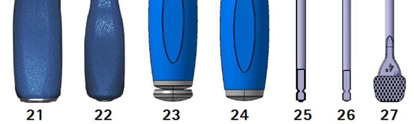
5 Legend 1 U-Joint Screwdriver (ME055R) 2 Ball Joint Screwdriver (ME404R) 3 Fixed Angle Screwdriver (ME056R) 4 Straight Screwdriver (ME057R) 5 U-Joint Drill (ME058R) 6 Ball Joint Drill (ME403R) 7 Fixed Angle Drill (ME059R) 8 U-Joint Bone Awl (ME060R) 9 Ball Joint Bone Awl (ME402R) 10 Fixed Angle Bone Awl (ME061R) 11 Straight Bone Awl (ME062R) 12 U-Joint Screw Extraction Tool (ME072R) 13 Soft Tissue Protection Sleeve (ME103) Δ 14 Interbody Inserter (ME063R) 15 All-in-One Guides for Interbody, 5-11mm (ME064R-ME070R) 16 Impactor (ME071R) 17 Tamp (ME073R) 18 Packing Block (ME074R) 19 Slotted Mallet (ME079T) 20 Multi-Tool Handle (ME075T) 21 Jeweler Inline Handle (GREA-HJ0011-S09) 22 Mini Fixed Inline Handle (GREA-HM0012-S09) 23 Modular Jeweler Handle (ME076R) 24 Modular Chuck Handle (ME077R) 25 Modular Rasps, AO, 13x16mm/15x17mm, 4 /7, 5-10mm lengths (US039R, US044R, US054R-US059R, US068R, US069R, US093R, US099R, US139R, US198R, US199R, US211R- US214R, US217R-US220R, US222R)* 26 Modular Trials 13x16mm/15x17mm, 4 /7, 5-11mm heights (ME126R-ME132R, ME142R-ME148R, ME133R-ME139R, ME232R - ME238R) Δ Δ 27 Dual Rasp/Trials 13x16mm/15x17mm, 4 /7, 5-11mm heights (ME096T-ME102T, ME105T-ME125T) Δ Instrument offered upon customer request only. Not included in the instrument set. in Set # ST0652 only in Set # ST0652 and ST0631 Δ Δ in Set # ST0652 and ST0630 in Set # ST0630 only in Set # ST0631 only Page 5 of 28
6 Symbols on product packages Caution, general warning symbol See documentation supplied with the product Indications & Contraindications The Arcadius XP C Instruments are used for the implantation of Arcadius XP C devices into the cervical spine. Indications and contraindications are listed in the Instructions for Use for Implants (SOP-AIS ). Safe Handling and Preparation Risk of injury caused by incorrect operation of the product. Attend appropriate product training before using the product. For information about product training, please contact your national B. Braun/Aesculap agency. CAUTION Federal law restricts this device to sale by, or on order of a physician Always follow the Instructions for Use of the Arcadius XP C Implants (SOP-AIS ) and the respective surgical techniques. Ensure that the products and accessories are operated and used only by persons with the requisite training, knowledge, and experience. Read, follow, and keep the Instructions for Use. Remove the transport packaging and thoroughly clean the new product manually, prior to its initial sterilization, see reprocessing procedure. Store any new or unused products in a dry, clean, and safe place. Prior to each use, inspect the product for loose, bent, broken, cracked, worn, or fractured components. Do not use the product if it is damaged or defective. Set aside the product if it is damaged. Replace any damaged components immediately with original spare parts if available. Safe Operation Risk of injury and/or product malfunction Always carry out a function check before using the product. Selection of Implant Size using Trial Implants The correct final size of Arcadius XP C Implant is determined by using the implant sizing trials (either Modular Trials or Dual Rasp/Trials). Connect the Modular Trial to the desired Handle (ME076R, ME077R, GREA-HJ0011-S09, or GREA-HM0012-S09) prior to advancing the trial into the disc space. Page 6 of 28
7 CAUTION Anterior osteophytes in the surgical site may prevent desired positioning of a trial and will likely prevent desired positioning of the Arcadius XP C Implant. It is recommended to remove interfering anterior osteophytes before implant insertion. Position the trial in the correct cranial/caudal alignment and carefully insert it into the disc space. Although the trials have depth stops, use fluoroscopy to check their position during insertion. Slotted Mallet (ME079T) can be used to aid insertion or removal of the Modular Trials or Dual Rasp/Trials. Do not apply excessive hammering force with the mallet. Risk of over-distraction, damaging the endplates / adjacent vertebral bodies / Modular Trial Implants / Dual Rasp Trials in the course of incorrectly applying the sizing trials. During the trial insertion, do not apply excessive bending / tilting / levering / hammering force to the Modular Trials or Dual Rasp/Trials. Under lateral and anterior-posterior fluoroscopy confirm the: o Trial depth, height, and lordosis o Endplate coverage (anterior-posterior / medial-lateral) o Midline placement o Implant rotation Select the implant size that corresponds with the final trial size chosen. Note Trials are color-coded to match the height of the corresponding Implant: 5mm Yellow 6mm Blue 7mm Red 8mm Green 9mm Natural 10mm Gray 11mm Black Risk of selecting incorrect implant size Fluoroscopy is mandatory to confirm the final trial size. Trials must provide good contact with the inferior and superior endplates. Therefore the proper footprint, height, and lordotic angle should be chosen for the disc space. Filling the Implant The Implant can be filled with bone or bone replacement material by using the Packing Block (ME074R) and Tamp (ME073R). Page 7 of 28
8 Implant Placement and Positioning Select and connect the appropriate All-in-One Guide (ME064R ME070R) to the Multi-Tool Handle (ME075T) by pressing and releasing the push button. Note All-in-One Guides are color-coded to match the height of the corresponding Implant: 5mm Yellow 6mm Blue 7mm Red 8mm Green 9mm Natural 10mm Gray 11mm Black Incorrect selection of the All-in-One Guide will result in implant damage and malfunction of the locking mechanism during the pilot hole preparation and bone screw insertion surgical steps. Confirm the selected All-in-One Guide corresponds to the selected Arcadius XP C cage. Align distal square of All-in-One Guide with internal square in the middle of the Arcadius XP C cage. Turn the Multi-Tool Handle wheel clockwise to thread inner shaft into the center fixation hole in the middle of the cage. Secure the selected Implant to the distal end of the All-in-One Guide by continuing to turn the wheel until it cannot be rotated any further. Use appropriate care when inserting the Implant. o Drive the Implant into the disc space using a suitable mallet. Note All-in-One Guides have a positive stop at the distal end to ensure the Implant is positioned flush with the anterior portion of the vertebral body. Inaccurate marking of the midline may result in incorrect positioning of the Implant. Always mark the midline under X-Ray visualization. Determine the center of the vertebral disc using the midline marker under X-Ray visualization. The Interbody Inserter (ME063R) with Multi-Tool Handle (ME075T) can be utilized as an alternative means of inserting the Implant into the disc space. Extreme caution must be exercised during Implant insertion due to the absence of a positive depth stop. If the Implant is inserted too far utilizing the Interbody Inserter (ME063R), the spinal canal and other posterior elements may be compressed Always use fluoroscopy to check the implant position during insertion. Excessive hammering may push the implant too far/deep into the disc space. Page 8 of 28
9 Risk of implant breakage Do not use excessive force when striking the implant connected to either the All-in-One Guide or the Interbody Inserter. Confirm an anatomically suitable position and orientation for the implant. o o o Obtain an AP fluoroscopic image to confirm midline placement of the device. Obtain a lateral fluoroscopic image to confirm the anterior edge of the Implant is seated flush with the anterior border of the vertebral body. Observe the X-Ray markers in both the AP and lateral views to ensure the Implant is not rotated within the disc space. Use Impactor (ME071R) to adjust the position (in AP direction) of the Implant as necessary if the All-in-One Guide/ Interbody Inserter was disengaged. Bone Screw Placement The Bone Awls (Fixed Angle Bone Awl (ME061R), U-Joint Bone Awl (ME060R), Ball Joint Bone Awl (ME402R), or Straight Bone Awl (ME062R)) and the Drills (U-Joint Drill (ME058R), Ball Joint Drill (ME403R), or Fixed Angle Drill (ME059R)) can be used to prepare a pilot hole for the bone screws at the intended screw placement site. Attach Bone Awls and Drills to the desired Handle (ME076R, ME077R, GREA-HJ0011-S09, or GREA-HM0012-S09) prior to using the instruments. Risk of damaging biological structures (spinal cord, spinal nerve roots, ligaments, soft tissues, etc.) and the Arcadius XP C cage if the bone awls and drills are used without the All-in-One Guide It is recommended to use the bone awls and drills with the All-in-One Guide Risk of damaging biological structures (spinal cord, spinal nerve roots, ligaments, soft tissues, etc.) with the drills and the bone awls, especially if the Arcadius XP C cage is placed off midline The instruments are sharp, always use the bone awls / drills under X-Ray control. Risk of damage to the Arcadius XP C cage in the course of incorrectly advancing the bone awls and drills Do not apply an excessive compressive / hammering / bending / tilting / levering force to the bone awls and the drills. Keep the instrument's tip directly aligned with the hole axis of the All-in-One Guide or the hole axis of the Arcadius XP C cage The bone awls and the drills must be pushed/advanced by hand only Risk of implant rotation Advance the drills and bone awls by hand while securely holding Arcadius XP C cage with either All-in-One Guide or Interbody Insertion Instrument. Don't disengage the All-in-One Guide/Interbody Insertion Instrument prior to fully inserting the bone screws. Attach a bone screw of appropriate length to selected self-retaining screwdriver (U-Joint Screwdriver (ME055R), Fixed Angle Screwdriver (ME056R), Ball Joint Screwdriver (ME404R), or Straight Screwdriver (ME057R)). Page 9 of 28
10 Engaging the screwdriver incorrectly when turning the bone screw into the Arcadius XP C cage may result in damage to the bone screws Fully insert the tip of the screwdriver into the bone screw. Guide the screw through the All-in-One Guide into the Arcadius XP C cage. Turn the screwdriver in a clockwise motion to advance the bone screw into the vertebral body Risk of damaging biological structures (spinal cord, spinal nerve roots, ligaments, soft tissues, etc.) while advancing incorrectly sized bone screws, especially if Arcadius XP C cage is placed off midline Always advance the bone screws under X-Ray control. Follow surgical technique, or training by Aesculap. Applying too much torque may result in stripping the bone thread by over tightening, damage to the bone screws or the Arcadius XP C cage Always use the screwdrivers with the Jeweler Handles (ME076R and GREA-HJ0011-S09). Adopt a thumb and two finger style grip to reduce the risk of applying too much torque. Risk of damage to the PEEK cage, or the bone screw head in the course of incorrectly driving the bone screw Do not apply an excessive bending/ tilting/ levering force to the Straight Screwdriver (ME057R) or Fixed Angle Screwdriver (ME056R) engaged in the bone screw. Keep the screwdrivers directly aligned with the axis of the bone screws. Insert the bone screws until they reach the final seated position, ensuring full engagement of the two locking mechanisms. Backing out and loosening of the bone screw occurs when the screw is not fully inserted into the cage Insert the bone screw until it gets fully engaged. Follow surgical technique, or training by Aesculap. Repeat the bone screw placement steps outlined above to insert the second bone screw through the Implant. Risk of insufficient stability or implant failure due to using fewer than two internal screw fixation provided Apply all of the screws or use an additional supplemental spinal fixation system that have been cleared for use in the cervical spine, such as cervical plating systems. Revision Locate implant to be revised, then securely engage either the appropriate All-in-One Guide or the Interbody Insertion Instrument (ME063R) with the Multi-Tool Handle (ME075T). Engage selected self-retaining screwdriver (U-Joint Screwdriver (ME055R), Ball Joint Screwdriver (ME404R), Fixed Angle Screwdriver (ME056R) and Straight Screwdriver (ME057R)) in the bone screw head. Retract the bone screw from the vertebral body by turning the screw in a counterclockwise motion. Use the U-Joint Screw Extraction Instrument (ME072R) to retract a free spinning screw. o Thread the instrument to the selected screw to be removed by engaging the internal thread mechanism (left-handed) in the screw head by rotating the instrument in a counterclockwise motion. Page 10 of 28
11 o Apply positive pull force and counterclockwise rotation to remove the screw. Repeat the bone screw removal process with the remaining bone screw in the Arcadius XP C cage. Carefully remove the implant from the disc space. Risk of injury to the patient Remove implant in the direction it was inserted. Excessive force during extraction may cause implant to impact the surrounding tissues. General Caution should be taken while operating the Multi-Tool Handle (ME075T). Activating the PRESS button on the Multi-Tool Handle (ME075T) while actively using the instrument can result in the instrument shaft detaching from the handle Do not cover the PRESS button with hand when utilizing fully assembled instruments. Caution should be taken while operating the instrument handles: the Multi-Tool Handle (ME075T) along with all quick connect handles: Jeweler Inline Handle (GREA-HJ0011-S09), Mini Fixed Inline Handle (GREA-HM0012-S09), Multi-Tool Handle (ME075T), Modular Jeweler Handle (ME076R), and Modular Chuck Handle (ME077R). Danger from improperly engaging the handles Prior to use, ensure that the instruments are securely connected to the handles. Caution should be taken while assembling the following modular instruments: Fixed Angle Screwdriver (ME056R), Fixed Angle Drill (ME059R), U-Joint Screwdriver (ME055R), U-Joint Drill (ME058R), U-Joint Screw Extraction Tool (ME072R), U-Joint Bone Awl (ME060R), and Straight Bone Awl (ME062R). Risk of not being able to securely engage implant or damaging the instruments. Ensure the instruments are correctly assembled prior to use. Danger from improperly assembled U-Joint Drill (ME058R): the drill bit may disengage from instrument shaft Prior to the surgery, ensure the drill bit is secured to the instrument shaft by firmly tightening the nut until it is fully threaded. Danger from improperly assembled U-Joint Screwdriver (ME055R): the screwdriver bit may disengage from the instrument shaft Prior to the surgery, ensure the screwdriver bit is secured to the instrument shaft by firmly tightening the nut until it is fully threaded. Page 11 of 28
12 Disassembly Fixed Angle Screwdriver (ME056R) and Fixed Angle Drill (ME059R) ME056R ME059R Figure 1: Disassembling ME056R and ME059R Unthread the nut [1] from the tube [2]. Pull out the tube [2] from the shaft sub-assembly. Remove the screwdriver bit [3] / drill bit [3] from the tube [2], see Fig. 1. U-Joint Instruments (ME055R, ME060R, ME058R, and ME072R) U-Joint Screwdriver (ME055R) Page 12 of 28
13 U-Joint Bone Awl (ME060R) U-Joint Drill (ME058R) U-Joint Screw Extraction Tool (ME072R) Figure 2: Disassembling ME055R, ME060R, ME058R and ME072R Remove the spring [1] covering the U-joint from the distal end of the shaft, see Fig. 2. Straight Bone Awl (ME062R) Figure 3: Disassembling ME062R Unthread the nut [1] from the tube [2]. Pull out the tube [2] from the shaft sub-assembly, see Fig. 3. Page 13 of 28
14 Assembly Fixed Angle Screwdriver (ME056R) and Fixed Angle Drill (ME059R) ME056R ME059R Figure 4: Assembling ME056R and ME059R Figure 5: Correct fully threaded position of the nut for ME056R and ME059R [1] Insert the screwdriver bit [3] / drill bit [3] into the tube [2]. Place the tube [2] over the shaft sub-assembly. Firmly thread the nut [1] over the tube [2] until it is fully threaded, see Fig. 4 and Fig. 5. Page 14 of 28
15 Danger from improperly assembled Fixed Angle Screwdriver (ME056R) or Fixed Angle Drill (ME059R): the screwdriver bit / drill bit may disengage from the instrument during shipment or operation Ensure the screwdriver bit [3] / drill bit [3] is secured to the tube by firmly tightening the nut [1] until it is fully threaded. See Fig. 4 and Fig. 5. U-Joint Instruments (ME055R, ME060R, ME058R, and ME072R) U-Joint Screwdriver (ME055R) U-Joint Bone Awl (ME060R) U-Joint Drill (ME058R) U-Joint Screw Extraction Tool (ME072R) Figure 6: Assembling ME055R, ME060R, ME058R and ME072R Page 15 of 28
16 Figure 7: Correct spring position Slide the spring [1] over the distal end until it is completely covering the U-joint. The end of the spring [2] must sit in the undercut, see Fig. 6 and Fig. 7. Danger from improperly assembled U-Joint Screwdriver (ME055R), U-Joint Bone Awl (ME060R), U- Joint Drill (ME058R), and U-Joint Screw Extraction Instrument (ME072R): The spring may disengage from the instrument shaft during shipment or operation Ensure the end of the spring [2] is seated in the undercut. Page 16 of 28
17 Soft Tissue Protection Sleeve (ME103) The Soft Tissue Protection Sleeve can be assembled to the following instruments: U-Joint Screwdriver (ME055R), U- Joint Bone Awl (ME060R), U-Joint Drill (ME058R) and U-Joint Screw Extraction Instrument (ME072R). Figure 8: Assembling ME103 (U-Joint Screwdriver shown) Figure 9: Correct sleeve position (U-Joint Screwdriver shown) Prior to assembling the Soft Tissue Protection Sleeve the spring [1] must be removed (see Disassembly instructions and Fig. 2) Slide the sleeve [1] over the distal end until hard stop, see Fig. 8 and Fig. 9. The sleeve [1] can be removed by applying force in the opposite assembly direction. Straight Bone Awl (ME062R) Place the tube [2] over the shaft sub-assembly. Figure 10: Assembling ME062R Firmly thread the nut [1] over the tube [2] until it is fully threaded, see Fig. 10. Page 17 of 28
18 Reprocessing Procedure General Safety Instructions Note Adhere to national statutory regulations, national and international standards and directives, and local, clinical hygiene instructions for sterile processing. Note For patients with Creutzfeldt-Jakob disease (CJD), suspected CJD or possible variants of CJD, observe the relevant national regulations concerning reprocessing of products. Note Mechanical reprocessing should be favored over manual cleaning as it gives better and more reliable results. Note Successful processing of this medical device can only be ensured if the processing method is validated. The operator/sterile processing technician is responsible for this. The recommended chemistry was used for process validation. Note For the latest information on reprocessing and material compatibility, see the reprocessing brochure at Aesculap US website General Information Dried or affixed surgical residues can make cleaning more difficult or ineffective and lead to corrosion. Therefore the time interval between application and processing should not exceed 6h. Neither pre-cleaning fixation temperatures >45 C/113 F nor disinfecting fixation agents (active ingredient: aldehydes/alcohols) should be used. Excessive amounts of neutralizing agents or basic cleaners may result in material degradation and/or fading, causing the laser marking to become unreadable on stainless steel. Residues containing chlorine or chlorides e.g. in surgical residues, medicines, saline solutions and in the service water used for cleaning, disinfection and sterilization will cause corrosion damage (pitting, stress corrosion) and result in destruction of stainless steel products. These must be removed by rinsing thoroughly with demineralized water then drying. Only process chemicals that have been tested and approved (e.g. FDA clearance) and which are compatible with the product s materials according to the chemical manufacturers recommendations may be used for processing the product. All the chemical manufacturer s application specifications must be strictly observed. Failure to do so can result in the following problems: Optical changes of materials, e.g. fading or discoloration of titanium or aluminum. For aluminum, the application/process solution only needs to be of ph>8 to cause visible surface changes. Material damage such as corrosion, cracks, fracturing, premature aging or swelling. Do not use metal cleaning brushes or other abrasives that would damage the product surfaces and could cause corrosion. Page 18 of 28

19 Disassembly of product before reprocessing Disassemble the product (if applicable) immediately after use, as described in the respective Disassembly section of the Instructions for Use. Preparations at the place of use Clean instruments as quickly as possible after usage. Prevent any significant contaminants from drying onto the instrument surface prior to cleaning. If applicable, rinse non-visible surfaces preferably with deionized water, e.g. with a disposable syringe. Remove any visible surgical residues to the extent possible with a damp, lint-free cloth. Transport the dry product in a sealed waste container, for cleaning and disinfection within 6 h. Preparation before cleaning Inspect tray to insure all debris have been removed. Repeat as many times as necessary until no visible debris remains in the tray. Disassemble each product (if applicable) prior to cleaning, see Disassembly section. Cleaning & Disinfection Product-specific safety notes on the reprocessing procedure CAUTION Damage to the product due to inappropriate cleaning/disinfecting agents and/or excessive temperatures Use cleaning and disinfecting agents according to the manufacturer s instructions which o are approved for plastics and high-grade steel, o do not degrade softeners (e.g. in silicone). Observe specifications regarding concentration, temperature and exposure time. Do not exceed the maximum allowable washing temperature. Use suitable cleaning/disinfecting agents if the product is put away in a wet condition. Rinse the product thoroughly with water prior to mechanical cleaning and disinfecting in order to prevent foam formation and reduced effectiveness of the process chemicals. Carry out ultrasonic cleaning: o As an effective mechanical supplement to manual cleaning/disinfection. o As a pre-cleaning procedure for encrusted residues, in preparation for mechanical cleaning/ disinfection. o As an integrated mechanical support for mechanical cleaning/disinfection. o For additional cleaning of products with residues left after mechanical cleaning/disinfection. Page 19 of 28
20 Validated Cleaning/Disinfection Procedures Validated Procedure Manual Cleaning with Immersion Disinfection Manual Cleaning with Ultrasound & Immersion Disinfection Mechanical Cleaning with Pre-Rinse Manual Pre- Cleaning with Immersion & subsequent Mechanical Cleaning Manual Pre- Cleaning with Ultrasound & subsequent Mechanical Cleaning Devices Specific Requirements Reference ME056R, ME057R, ME059R, ME061R, ME063R, ME071R, ME073R, ME074R, ME079T, ME103, Dual Rasp/Trials (ME096T-ME102T, ME105T- ME125T), Modular Trials (ME126R-ME132R, ME142R-ME148R, ME133R-ME139R, ME232R- ME238R), Modular Rasps (US039R, US044R, US054R-US059R, US068R, US069R, US093R, US099R, US139R, US198R, US199R, US211R- US214R, US217R-US220R, US222R), All-in-One Guides (ME064R-ME070R), ME075T 1 ME055R, ME058R, ME060R, ME062R, ME072R, ME076R, ME077R, ME402R, ME403R, ME404R, GREA-HJ0011-S09, GREA-HM0012-S09 ME057R, ME071R, ME073R, ME079T, Modular Rasps (US039R, US044R, US054R-US059R, US068R, US069R, US093R, US099R, US139R, US198R, US199R, US211R- US214R, US217R- US220R, US222R) 1 ME056R, ME059R, ME061R, ME063R, ME074R, ME103, Dual Rasp/Trials (ME096T-ME102T, ME105T-ME125T), Modular Trials (ME126R- ME132R, ME142R-ME148R, ME133R-ME139R, ME232R-ME238R), All-in-One Guides (ME064R- ME070R), ME075T 1 Disposable syringe 20ml Cleaning brush: TA011944, TTE654202, or GK When cleaning products with movable hinges, ensure these are in an open position; move joint while cleaning Drying phase: Use lint-free cloth or medical compressed air Disposable syringe 20ml Cleaning brush: TA011944, TTE654202, or GK When cleaning products with movable hinges, ensure these are in an open position; move joint while cleaning Drying phase: Use lint-free cloth or medical compressed air Disposable syringe 20ml Cleaning brush: TA011944, TTE654202, or GK Place products in a tray suitable for cleaning Disposable syringe 20ml Cleaning brush: TA011944, TTE654202, or GK When cleaning products with movable hinges, ensure these are in an open position; move joint while cleaning Place products in tray suitable for cleaning (avoid rinsing blind spots) with any hinges open. Disposable syringe 20ml Cleaning brush: TA011944, TTE654202, or GK Place products in a tray suitable for cleaning (avoid rinsing blind spots) with any hinges open. Chapter: Validated Cleaning/ Disinfection Procedures Sub-Chapter: Manual Cleaning with Immersion Disinfection Chapter: Validated Cleaning/ Disinfection Procedures Sub-Chapter: Manual Cleaning with Ultrasound & Immersion Disinfection Chapter: Validated Cleaning/ Disinfection Procedures Sub-Chapter: Manual Cleaning with Pre-Rinse Chapter: Validated Cleaning/ Disinfection Procedures Sub-Chapter: Manual Pre-Cleaning with Immersion & Subsequent Mechanical Cleaning Chapter: Validated Cleaning/ Disinfection ME055R, ME058R, ME060R, ME062R, ME072R, Procedures ME076R, ME077R, ME402R, ME403R, ME404R, Sub-Chapter: GREA-HJ0011-S09, GREA-HM0012-S09 Manual Pre-Cleaning with Ultrasound & Subsequent Mechanical Cleaning 1 Prior to manual cleaning with immersion, completely immerse parts in an appropriate enzymatic manual cleaning solution and allow to soak for 4 minutes. Prior to manual disinfection, allow water to drip off for a sufficient length of time to prevent dilution of the disinfecting solution. After manual cleaning/disinfection, check visible surfaces visually for residues. Repeat the cleaning/disinfection process if necessary. Page 20 of 28
21 Manual Cleaning with Immersion Disinfection ME056R, ME057R, ME059R, ME061R, ME063R, ME071R, ME073R, ME074R, ME079T, ME103, Dual Rasp/Trials (ME096T-ME102T, ME105T-ME125T), Modular Trials (ME126R-ME132R, ME142R-ME148R, ME133R-ME139R, ME232R-ME238R), Modular Rasps (US039R, US044R, US054R-US059R, US068R, US069R, US093R, US099R, US139R, US198R, US199R, US211R- US214R, US217R- US220R, US222R), All-in-One Guides (ME064R-ME070R), ME075T Phase Step T [ F/ C] t [min] Conc. [%] Water Quality I Pre-Cleaning RT (cold) >15 See # 3 D-W Chemical Aldehyde-free, phenol-free, and QUAT-free concentrate, ph II Intermediate rinse RT (cold) 1 - D-W - III Disinfection RT (cold) 15 See # 3 D-W IV Final rinse RT (cold) 1 - Distilled Water Aldehyde-free, phenol-free, and QUAT-free concentrate, ph V Drying RT D-W: Drinking water RT: Room temperature 1 Recommended: Steris Prolystica 2x concentrate enzymatic presoak and cleaner 2 Recommended: Steris Prolystica 2x concentrate neutral detergent 3 Prepare according to manufacturer s instructions Note information on appropriate cleaning brushes and disposable syringes. See Cleaning & Disinfection Procedures section. For ME075T: o Prior to manual cleaning with immersion, completely immerse parts in an appropriate enzymatic manual cleaning solution and allow to soak for 4 minutes. Phase I Fully immerse the product in a prepared room temperature enzymatic detergent solution (Recommended: Steris Prolystica) for at least 15 min. Ensure all accessible surfaces are moistened. Rinse lumens at least five times with disposable syringe (20ml). Ensure that all accessible surfaces are moistened. Thoroughly clean the product with a suitable soft bristled brush in the solution until all discernible residues have been removed from the surface. Brush any non-visible surfaces with a suitable soft-bristled brush for 1 min. Mobilize non-rigid components, such as set screws, links, etc. during cleaning. Thoroughly rinse these components with the cleaning disinfectant solution 5x with a disposable syringe. Phase II Rinse/flush the product thoroughly (all accessible surfaces) under running water. Mobilize non-rigid components, such as set screws, joints, etc. during rinsing. Drain any remaining water fully. Phase III Fully immerse the product in the disinfectant solution (Recommended: Steris Prolystica). Mobilize non-rigid components, such as set screws, joints, etc. during rinsing. Visually inspect all lumens and gaps to ensure there is no remaining contamination. Thoroughly rinse these components with the cleaning solution ( 5 times), using a disposable syringe (20 ml). Ensure all accessible surfaces are moistened. - Page 21 of 28
22 Phase IV Rinse/flush the product thoroughly (all accessible surfaces) under running desalinated water. Mobilize non-rigid components, such as set screws, joints, etc. during final rinse. Rinse lumens with a disposable syringe (20 ml) at least five times. Drain any remaining water fully. Phase V Dry the product in the drying phase with suitable equipment (e.g. lint-free cloth, compressed filtered air), see Cleaning & Disinfection Procedures. Manual Cleaning with Ultrasound & Immersion Disinfection ME055R, ME058R, ME060R, ME062R, ME072R, ME402R, ME403R, ME404R, GREA-HJ0011-S09, GREA-HM0012-S09 T t Conc. Water Phase Step Chemical [ F/ C] [min] [%] Quality I Pre-Cleaning RT (cold) >15 See # 3 D-W Aldehyde-free, phenol-free, and QUAT-free concentrate, ph II Intermediate rinse RT (cold) 1 - D-W - III Ultrasonic Cleaning RT (cold) 15 See # 3 D-W IV Final rinse RT (cold) 1 - Distilled Water Aldehyde-free, phenol-free, and QUAT-free concentrate, ph V Drying RT D-W: Drinking water RT: Room temperature 1 Recommended: Steris Prolystica 2x concentrate enzymatic presoak and cleaner 2 Recommended: Steris Prolystica 2x concentrate neutral detergent 3 Prepare according to manufacturer s instructions - Note information on appropriate cleaning brushes and disposable syringes. See Validated Cleaning/Disinfection Procedures section. Phase I Fully immerse the product in a prepared room temperature enzymatic detergent solution (Recommended: Steris Prolystica) for at least 15 min. Ensure all accessible surfaces are moistened. Rinse lumens at least five times with a disposable syringe (20ml). Ensure all accessible surfaces are moistened. Thoroughly clean the product with a suitable soft bristled brush in the solution until all discernible residues have been removed from the surface. Brush any non-visible surfaces with a suitable soft-bristled brush for 1 min. Mobilize non-rigid components, such as set screws, links, etc. during cleaning. Thoroughly rinse these components with the cleaning disinfectant solution 5x with a disposable syringe. Phase II Rinse/flush the product thoroughly (all accessible surfaces) under running water. Mobilize non-rigid components, such as set screws, joints, etc. during rinsing. Drain any remaining water fully. Page 22 of 28
23 Phase III Prepare neutral detergent (Recommended: Steris Prolystica) in an ultrasonic cleaning bath. Clean the product in an ultrasonic cleaning bath (frequency 35 khz) for at least 15 min. Ensure all accessible surfaces are immersed and acoustic shadows are avoided. Mobilize non-rigid components, such as set screws, joints, etc. during rinsing. Visually inspect all lumens and gaps to ensure there is no remaining contamination. Thoroughly rinse these components 5 times with the cleaning solution, using a disposable syringe (20 ml). Ensure all accessible surfaces are moistened. Phase IV Rinse/flush the product thoroughly (all accessible surfaces) under running desalinated water. Mobilize non-rigid components, such as set screws, joints, etc. during final rinse. Rinse lumens with a disposable syringe (20 ml) at least five times. Drain any remaining water fully. Phase V Dry the product in the drying phase with suitable equipment (e.g. lint-free cloth, compressed filtered air), see Cleaning & Disinfection Procedures. Mechanical Cleaning with Pre-Rinse ME057R, ME071R, ME073R, ME079T, Modular Rasps T Phase Step [ F/ C] t [min] Conc. [%] Water Quality I Wash Phase I 131/55 5 See # 3 D-W II Wash Phase II 131/ T-W II Rinse 194/90 2 See # 3 Distilled Water Chemical Aldehyde-free, phenol-free, QUATfree enzymatic cleaner, ph ,4 Aldehyde-free, phenol-free, QUATfree neutral detergent, ph ,4 IV Drying 194/ D-W: Drinking water T-W: Tap water 1 Recommended: Steris Prolystica 2x concentrate enzymatic presoak and cleaner 2 Recommended: Steris Prolystica 2x concentrate neutral detergent 3 Prepare according to manufacturer s instructions 4 Always follow the manufacturer s specifications for automatic washer-sterilizers and use a free-rinsing, low sudsing detergent with a neutral ph ( ). Due to variations in water quality, the type of detergent and its concentrations may require adjustment for optimal disinfection and cleaning. Before placing in the washer disinfector, immerse products in drinking water and agitate all moving parts (e.g. with a brush) until there is no evidence of soil Place the pre-rinsed products in a tray that is suitable for cleaning (avoiding rinsing blind spots). Place any hinged instruments in the tray with their hinges open. Check visible surfaces for residues after mechanical cleaning/disinfection. - Page 23 of 28
24 Manual Pre-Cleaning with Immersion & Subsequent Mechanical Cleaning ME056R, ME059R, ME061R, ME063R, ME074R, ME103, Dual Rasp/Trials (ME096T-ME102T, ME105T-ME125T), Modular Trials (ME126R- ME132R, ME142R-ME148R, ME133R-ME139R, ME232R-ME238R), All-in-One Guides (ME064R-ME070R), ME075T Phase Step T [ F/ C] t [min] Conc. [%] Water Quality I Pre-Cleaning RT (cold) >15 See # 3 D-W Chemical Aldehyde-free, phenol-free, and QUATfree concentrate, ph II Intermediate rinse RT (cold) 1 - D-W - III Disinfection RT (cold) 15 See # 3 D-W IV Rinse RT (cold) 1 - Distilled Water V Wash Phase I 131/55 5 See # 3 D-W VI Wash Phase II 131/ T-W VII Rinse 194/90 2 See # 3 Distilled Water Aldehyde-free, phenol-free, and QUATfree concentrate, ph Aldehyde-free, phenol-free, QUAT-free enzymatic cleaner, ph ,4 Aldehyde-free, phenol-free, QUAT-free neutral detergent, ph ,4 VIII Drying 194/ D-W: Drinking water T-W: Tap water RT: Room temperature 1 Recommended: Steris Prolystica 2x concentrate enzymatic presoak and cleaner 2 Recommended: Steris Prolystica 2x concentrate neutral detergent 3 Prepare according to manufacturer s instructions 4 Always follow the manufacturer s specifications for automatic washer-sterilizers and use a free-rinsing, low sudsing detergent with a neutral ph ( ). Due to variations in water quality, the type of detergent and its concentrations may require adjustment for optimal disinfection and cleaning. Prior to pre-cleaning with immersion, the Multi-Tool Handle (ME075T) instrument must be completely immersed in an appropriate enzymatic manual cleaning solution and allowed to soak for 4 minutes. Protective sleeve on tip of the Bone Awl (ME061R) must be fully retracted to expose groove and ensure all evidence of soil is removed from the groove during the manual cleaning process (refer to Phase I below). Phase I Fully immerse the product in a prepared room temperature enzymatic detergent solution (Recommended: Steris Prolystica) for at least 15 min. Ensure all accessible surfaces are moistened. Rinse lumens at least five times with disposable syringe (20ml). Ensure that all accessible surfaces are moistened. Thoroughly clean the product with a suitable soft bristled brush in the solution until all discernible residues have been removed from the surface. Brush any non-visible surfaces with a suitable soft-bristled brush for 1 min. Mobilize non-rigid components, such as set screws, links, etc. during cleaning. Thoroughly rinse these components with the cleaning disinfectant solution 5x with a disposable syringe. Phase II Rinse/flush the product thoroughly (all accessible surfaces) under running water. Mobilize non-rigid components, such as set screws, joints, etc. during rinsing. Drain any remaining water fully. - Page 24 of 28
25 Phase III Fully immerse the product in the disinfectant solution (Recommended: Steris Prolystica). Mobilize non-rigid components, such as set screws, joints, etc. during rinsing. Visually inspect all lumens and gaps to ensure there is no remaining contamination. Thoroughly rinse these components with the cleaning solution ( 5 times), using a disposable syringe (20 ml). Ensure all accessible surfaces are moistened. Phase IV Rinse/flush the product thoroughly (all accessible surfaces) under running desalinated water. Mobilize non-rigid components, such as set screws, joints, etc. during final rinse. Rinse lumens with a disposable syringe (20 ml) at least five times. Drain any remaining water fully. Phases V-VIII (Washer Disinfector) Place the products in a tray that is suitable for cleaning (avoiding rinsing blind spots). Place any hinged instruments in the tray with their hinges open. Check visible surfaces for residues after mechanical cleaning/disinfection. Manual Pre-Cleaning with Ultrasound & Subsequent Mechanical Cleaning ME076R, ME077R Phase Step T [ F/ C] t [min] Conc. [%] Water Quality I Pre-Cleaning RT (cold) >15 See # 3 D-W Chemical Aldehyde-free, phenol-free, and QUAT-free concentrate, ph II Intermediate rinse RT (cold) 1 - D-W - III Ultrasonic Cleaning RT (cold) 15 See # 3 D-W Aldehyde-free, phenol-free, and QUAT-free concentrate, ph IV Rinse RT (cold) 1 - Distilled Water - V Wash Phase I 131/55 5 See # 3 D-W Aldehyde-free, phenol-free, QUATfree enzymatic cleaner, ph ,4 VI Wash Phase II 131/ T-W VII Rinse 194/90 2 See # 3 Distilled Water Aldehyde-free, phenol-free, QUATfree neutral detergent, ph ,4 VIII Drying 194/ D-W: Drinking water T-W: Tap water RT: Room temperature 1 Recommended: Steris Prolystica 2x concentrate enzymatic presoak and cleaner 2 Recommended: Steris Prolystica 2x concentrate neutral detergent 3 Prepare according to manufacturer s instructions 4 Always follow the manufacturer s specifications for automatic washer-sterilizers and use a free-rinsing, low sudsing detergent with a neutral ph ( ). Due to variations in water quality, the type of detergent and its concentrations may require adjustment for optimal disinfection and cleaning. - Page 25 of 28
26 Phase I Fully immerse the product in a prepared room temperature enzymatic detergent solution (Recommended: Steris Prolystica) for at least 15 min. Ensure all accessible surfaces are moistened. Rinse lumens at least five times with a disposable syringe (20ml). Ensure all accessible surfaces are moistened. Thoroughly clean the product with a suitable soft bristled brush in the solution until all discernible residues have been removed from the surface. Brush any non-visible surfaces with a suitable soft-bristled brush for 1 min. Mobilize non-rigid components, such as set screws, links, etc. during cleaning. Thoroughly rinse these components with the cleaning disinfectant solution 5x with a disposable syringe. Phase II Rinse/flush the product thoroughly (all accessible surfaces) under running water. Mobilize non-rigid components, such as set screws, joints, etc. during rinsing. Drain any remaining water fully. Phase III Prepare neutral detergent (Recommended: Steris Prolystica) in an ultrasonic cleaning bath. Clean the product in an ultrasonic cleaning bath (frequency 35 khz) for at least 15 min. Ensure all accessible surfaces are immersed and acoustic shadows are avoided. Mobilize non-rigid components, such as set screws, joints, etc. during rinsing. Visually inspect all lumens and gaps to ensure there is no remaining contamination. Thoroughly rinse these components 5 times with the cleaning solution, using a disposable syringe (20 ml). Ensure all accessible surfaces are moistened. Phase IV Rinse/flush the product thoroughly (all accessible surfaces) under running desalinated water. Mobilize non-rigid components, such as set screws, joints, etc. during final rinse. Rinse lumens with a disposable syringe (20 ml) at least five times. Drain any remaining water fully. Phases V-VIII (Washer Disinfector) Place the products in a tray that is suitable for cleaning (avoiding rinsing blind spots). Place any hinged instruments in the tray with their hinges open. Check visible surfaces for residues after mechanical cleaning/disinfection. Inspection, Maintenance, and Functional Checks CAUTION Damage (metal seizure/friction corrosion) to the product caused by insufficient lubrication Prior to functional checks, lubricate moving parts (e.g. joints, pusher components, and threaded rods) at the marked lubrication points, using maintenance oil suitable for the respective sterilization process. Allow the product to cool to room temperature. After each complete cleaning, disinfection, and drying cycle, check that the product is: clean, dry, operational, and damagefree (e.g. no broken insulation or loose, bent, broken, cracked, worn, or fractured components). Dry the product if it is wet or damp. Repeat cleaning and disinfection if product still has visible impurities or contamination. Check that the product functions correctly. Page 26 of 28
27 Immediately put aside damaged or inoperable products and send them to Aesculap Technical Service, see Technical Service section. Assemble any disassembled products, see Assembly section. Check for compatibility with associated products. Packaging Appropriately protect products to prevent damage of fine working tips. Those instruments are: ME055R, ME056R, ME057R, ME058R, ME059R, Me060R, ME061R, ME062R, ME402R, ME403R, and ME404R. Place the product in its holder or in a suitable tray. Ensure all cutting edges are protected. Pack trays appropriately for the intended sterilization process (e.g. in Aesculap sterile containers). Ensure the packaging provides sufficient protection against recontamination of the product during storage. Steam Sterilization Aesculap advises against sterilizing the device by immediate use steam sterilization (i.e. flash sterilization) or chemical sterilization. Sterilization may be accomplished by a standard pre-vacuum cycle in a steam autoclave. Do not stack containers during sterilization. To achieve a sterility assurance level of 10-6, Aesculap recommends the following parameters: Aesculap Orga TM Tray/Sterile container (perforated bottom) Minimum cycle parameters* Sterilization Temp. Time Minimum Drying Time Method F/ C Pre-vacuum 270/132 4 min 30 min *Aesculap has validated the above sterilization cycles and has the data on file. The validation was accomplished in an Aesculap sterile container cleared by the FDA for sterilization and storage of these products. Other sterilization cycles may also be suitable, however individuals or hospitals not using the recommended method are advised to validate any alternative method using appropriate laboratory techniques. Use an FDA cleared accessory to maintain sterility after processing, such as a wrap, pouch, etc. When sterilizing several products at the same time in a steam sterilizer, ensure the maximum load capacity of the steam sterilizer specified by the manufacturer is not exceeded. Disposal If this device is/was used in a patient with or suspected of having Creutzfeldt-Jakob Disease (CJD), the device cannot be reused and must be destroyed due to the inability to reprocess or sterilize to eliminate the risk of cross contamination. Adhere to national regulations when disposing of or recycling the products, their components and all packaging Page 27 of 28
28 Technical Service Risk of injury and/or product malfunction Do not modify the product. If any Arcadius XP C Spinal System instrument or its components require repair or maintenance, return the entire instrument set in a sturdy box with adequate foam, bubble wrap, or other packaging material to protect it. Instruments returned to Aesculap Implant Systems for repair must have a statement which testifies that each instrument has been thoroughly cleaned and disinfected. Failure to supply evidence of cleaning and disinfection will result in a cleaning charge and delayed processing of your instrument repair. Send the packaged instrument to: Aesculap Implant Systems, LLC. Attn. Aesculap Technical Services 615 Lambert Pointe Drive Hazelwood, St. Louis, MO Aesculap Repair Hotline Phone: +1 (800) Fax: +1 (314) CAUTION FEDERAL LAW RESTRICTS THIS DEVICE TO SALE BY OR ON THE ORDER OF A PHYSICIAN. Product information and complaints Aesculap Implant Systems, LLC Corporate Parkway Center Valley, PA SOP-AIS Rev. 2 02/18 Page 28 of 28
Aesculap Implant Systems
 Aesculap Implant Systems Aesculap Implant Systems Spine USA Instructions for use/technical description Page 1 of 9 A 2 1 4 B 3 Page 2 of 9 USA Aesculap Implant Systems Instrument Legend A Rigid Inserter
Aesculap Spine Instructions for use
 Aesculap Spine S 4 Spondylolisthesis Reduction Instrument (SRI) Instructions for use S 4 Spondylolisthesis Reduction Instrument (SRI) 5 4 3 2 Fig. 1 1 9 10 11 8 6 7 Fig. 2 Aesculap Spine S 4 Spondylolisthesis
M6-C Artificial Cervical Disc Surgical Instruments
 CARE AND HANDLING INSTRUCTIONS Orthofix Inc. 3451 Plano Parkway Lewisville, Texas 75056-9453 U.S.A. 1-214-937-3199 1-888-298-5700 www.orthofix.com OSI-CustomerService@Orthofix.com Spinal Kinetics LLC,
Yasargil Permanent Aneurysm Clips
 Yasargil Permanent Aneurysm Clips Yasargil aneurysm clips Figure captions 1 Yasargil Phynox aneurysm clip, example of a straight clip 2 Yasargil titanium aneurysm clip, example of a straight clip 3 Yasargil
LBL-014. Rev
 Package Insert Z- CLAMP ISP System Device Description: The Z-CLAMP ISP System is supplemental fixation device consisting of a variety of shapes and sizes of one-level lumbar and sacral plates and screws.
The A-Space SIBD Spinal System is a stand-alone device intended to be used with the four supplied bone screws if no supplemental fixation is used.
 Instructions for Aesculap Implant Systems A-Space SIBD Spinal System Indications The A-Space SIBD Spinal System is a stand-alone device intended to be used with the four supplied bone screws if no supplemental
100 Interpace Parkway Parsippany, NJ
 100 Interpace Parkway Parsippany, NJ 07054 www.biometspine.com 800-526-2579 All trademarks are the property of Biomet, Inc. or one of its subsidiaries, unless otherwise indicated. Rx Only. 2009 EBI, LLC.
INSTRUCTIONS FOR USE AND CARE
 DIAMONDS INSTRUCTIONS FOR USE AND CARE DIAMONDS, MULTI-USE, FRICTION GRIP Quala Diamonds are a rotary cutting device made of stainless steel and coated with diamond particles on the working end. It is
Preparation Instructions for the CAMLOG /CONELOG Implant System
 J8000.0032 Rev.6 EN 06/2015 Preparation Instructions for the CAMLOG /CONELOG Implant System ENGLISH The following descriptions contain detailed instructions on cleaning, disinfection and sterilization
Zavation Z-Link Cervical
 Zavation Z-Link Cervical Interbody Plate: Interbody Plate Screw Quarter turn locks for each screw Locks use same driver as used for inserting screws 30 caudal and cephalad biased angles 15 midline biased
nva Anterior Lumbar Interbody Fusion System
 nva Anterior Lumbar Interbody Fusion System 1 IMPORTANT INFORMATION FOR PHYSICIANS, SURGEONS, AND/OR STAFF The nv a, nv p, and nv t are an intervertebral body fusion device used in the lumbar spine following
SURGICAL TECHNIQUE GUIDE BRECKENRIDGE. Intervertebral Body/VBR Fusion System. ACDF Anterior Cervical Discectomy and Fusion
 SURGICAL TECHNIQUE GUIDE TM BRECKENRIDGE Intervertebral Body/VBR Fusion System ACDF Anterior Cervical Discectomy and Fusion The following general Surgical Technique Guide is for illustrative purposes only.
Velocity Orthopedics Instrument Cleaning and Sterilization
 Velocity Orthopedics Instrument Cleaning and Sterilization It is important to read the Instructions For Use in its entirety prior to using the product. Caution: Federal law (USA) restricts this device
SURGICAL TECHNIQUE GUIDE BRECKENRIDGE. Intervertebral Body/VBR Fusion System. Oblique Lumbar Interbody Fusion
 SURGICAL TECHNIQUE GUIDE BRECKENRIDGE TM Intervertebral Body/VBR Fusion System Oblique Lumbar Interbody Fusion The following general Surgical Technique Guide is for illustrative purposes only. As with
Veyron -C Anterior Cervical System Surgical Technique
 Veyron -C Anterior Cervical System Surgical Technique 2 Veyron-C Anterior Cervical System Surgical Technique Veyron-C Anterior Cervical System Surgical Technique Description, Indications & Contraindications...3
a perfect fit INSTRUCTION MANUAL CAMLOG TORQUE WRENCH WITH CONTINUOUS TORQUE ADJUSTMENT Handling Sterilization Care
 a perfect fit INSTRUCTION MANUAL CAMLOG TORQUE WRENCH WITH CONTINUOUS TORQUE ADJUSTMENT Handling Sterilization Care CAMLOG TORQUE WRENCH WITH CONTINUOUS TORQUE ADJUSTMENT INTRODUCTION The torque wrench
Imola Lateral IBF System Surgical Technique
 Imola Lateral IBF System Surgical Technique IMOLA CIRCUIT TABLE OF CONTENTS Design Rationale Instructions for Use Surgical Technique 1. Table Mounting 2. Surgical Planning & Targeting 3. Access and Preparation
nvt Transforaminal Lumbar Interbody Fusion System
 nvt Transforaminal Lumbar Interbody Fusion System 1 IMPORTANT INFORMATION FOR PHYSICIANS, SURGEONS, AND/OR STAFF The nv a, nv p, and nv t are an intervertebral body fusion device used in the lumbar spine
nvp Posterior Lumbar Interbody Fusion System
 nvp Posterior Lumbar Interbody Fusion System 1 IMPORTANT INFORMATION FOR PHYSICIANS, SURGEONS, AND/OR STAFF The nv a, nv p, and nv t are an intervertebral body fusion device used in the lumbar spine following
Cervical Solutions. Optio-C Anterior Cervical Plate. with Allograft/Autograft. Surgical Technique Guide
 Cervical Solutions Optio-C Anterior Cervical Plate with Allograft/Autograft Surgical Technique Guide 2 Optio-C Anterior Cervical Plate with Allograft/Autograft Surgical Technique Guide The Optio-C System
BAK/C Cervical Anterior Interbody Fusion System
 Surgical Technique BAK/C Cervical Anterior Interbody Fusion System The Comfortable Choice for Cervical Fusion BAK/C Cervical Surgical Technique 1 The BAK/C Cervical Fusion System is an alternative to conventional
Manufacturer s information
 WARNINGS: Observe the standard German accident prevention regulations (UVV) We are not aware of any warnings if the instructions for the devices and disinfection and cleaning agents to be used are followed.
Valencia Pedicle Screw Surgical Technique
 Valencia Pedicle Screw Surgical Technique VALENCIA CIRCUIT TABLE OF CONTENTS Design Rationale Indications for Use Surgical Technique 1. Pedicle Preparation 2. Screw Insertion 3. Rod Placement 4. Locking
SI-BONE ifuse Implant System Instruments Hospital Cleaning and Sterilization Instructions 0344
 HOW SUPPLIED The SI-BONE instruments are supplied non-sterile and must be cleaned and sterilized prior to use. The ifuse Implant is provided separately and supplied sterile. Please refer to the ifuse System
Reprocessing Guide. Autoclavable Arthroscope and Hardware Sterilization Tray
 Reprocessing Guide Autoclavable Arthroscope and Hardware Sterilization Tray 0233032116 Contents Introduction...2 Intended Use of Sterilization Trays...4 Warnings...5 Cautions...5 Instructions...6 Sterilization
Solitaire Anterior Spinal System
 Surgical Technique Solitaire Anterior Spinal System Independent Stabilization for the Anterior Column Available in Titanium and Contents Introduction... Page 1 Design Features... Page 2 Instruments...
Scope This policy applies to all personnel and departments that clean, prepare and/or sterilize items intended for patient care use.
 Dental Sterilization Procedures Policy Number VIM4(4)-10 Purpose The purpose of this policy is to ensure patient and employee safety when using instruments with potential for exposure to bloodborne pathogens
ProUltra ULTRASONIC SURGICAL TIPS
 ProUltra ULTRASONIC SURGICAL TIPS EN FOR DENTAL USE ONLY DIRECTIONS FOR USE (ULTRASONIC SURGICAL TIPS) A0640 A0650 Satelec M3 x 0,6 EMS M3 x 0,5 ProUltra Surgical tips Ref. A0640 Ref. A0650 1) INDICATIONS
TABLE OF CONTENTS. Vault C Anterior Cervical Discectomy 2 and Fusion (ACDF) System Overview. Implants 3. Instruments 5. Surgical Technique 10
 System Overview. Implants 3. Instruments 5. Surgical Technique 10") Surgical Technique TABLE OF CONTENTS Vault C Anterior Cervical Discectomy 2 and Fusion (ACDF) System Overview Indications 2 Implants 3 Instruments 5 Surgical Technique 10 1. Preoperative planning 10 2.
Surgical Technique TABLE OF CONTENTS Vault C Anterior Cervical Discectomy 2 and Fusion (ACDF) System Overview Indications 2 Implants 3 Instruments 5 Surgical Technique 10 1. Preoperative planning 10 2.
Aesculap Long and Short Ventriculoscope Systems Instructions for Use
 Aesculap Long and Short Ventriculoscope Systems Instructions for Use INDICATIONS FOR USE Aesculap s short and long ventriculoscopes and associated instruments are designed for visual orientation and therapeutic
VECTRA-T SURGICAL TECHNIQUE. The Translational Anterior Cervical Palate System. This publication is not intended for distribution in the USA.
 VECTRA-T The Translational Anterior Cervical Palate System This publication is not intended for distribution in the USA. SURGICAL TECHNIQUE Image intensifier control This description alone does not provide
EXACTECH SPINE. Operative Technique. Cervical Spacer System. Surgeon focused. Patient driven. TM
 EXACTECH SPINE Operative Technique Cervical Spacer System Surgeon focused. Patient driven. TM ACAPELLA ONE Acapella One Cervical Spacer System is an anterior cervical discectomy and fusion device with
Gallery Laminoplasty Spine System
 Surgical Technique Gallery Laminoplasty Spine System A smart, simple to use system with intuitive design features. Smart Plate Design Three hole, cobra head design Plates with hook or standard plates available
Endoscopic Technology. Operating Manual. Cannula system
 Endoscopic Technology Operating Manual AlphaPort Cannula system This manual contains proprietary information that is protected by copyright. All rights are reserved. This manual or excerpts thereof may
MATERIAL SAFETY DATA SHEET (MSDS) Information about stainless steel for Surgical/Dental/Orthodontic Instruments.
 Information about stainless steel for Surgical/Dental/Orthodontic Instruments.") MATERIAL SAFETY DATA SHEET (MSDS) THE INFORMATION BELOW IS BELIEVED TO BE ACCURATE AND REPRESENTS THE BEST INFORMATION CURRENTYLY AVAILABLE TO US. HOWEVER, WE MAKE NO WARRANTY OF MERCHANTABILITY OR ANY
MATERIAL SAFETY DATA SHEET (MSDS) THE INFORMATION BELOW IS BELIEVED TO BE ACCURATE AND REPRESENTS THE BEST INFORMATION CURRENTYLY AVAILABLE TO US. HOWEVER, WE MAKE NO WARRANTY OF MERCHANTABILITY OR ANY
Table of Contents.
 surgical technique The Ambassador TM Anterior Cervical Plate System is a versatile system of implants and instruments with a variety of sizes to provide optimal anatomic compatibility. The integrated cam
ATHLET VBR. The real winner. VBR in PEEK-OPTIMA PRODUCT INFORMATION
 ATHLET VBR in PEEK-OPTIMA The real winner PRODUCT INFORMATION VBR PRODUCT INFORMATION The Concept A vertebral body replacement requires top performance Simple intra- and postoperative control Anatomic
Bryan-Dumon Series II Rigid Bronchoscope and Stent Placement Kit USER MANUAL
 Bryan-Dumon Series II Rigid Bronchoscope and Stent Placement Kit USER MANUAL Table of Contents Bryan-DUmon Series II rigid bronchoscope 1. 2. 3. 4. 5. Diagram and Overview Universal Barrel Bronchial and
NewBridge. Laminoplasty Fixation INTERNATIONAL EDITION
 NewBridge L A M I N O P L A S T Y F I X A T I O N S Y S T E M Laminoplasty Fixation INTERNATIONAL EDITION Table of Contents 1 INTRODUCTION 2 PRE-OPERATIVE 3 OPERATIVE 10 INSTRUCTIONS FOR USE 12 PART NUMBERS
Cervical Spacer System surgical technique
 Blackhawk TM Cervical Spacer System surgical technique Blackhawk TM The BLACKHAWK Cervical Spacer System is designed to provide biomechanical stabilization as an adjunct to fusion. Spinal fixation should
Headless Compession Screw 2.5 / 3.0
 SURGICAL TECHNIQUE Headless Compession Screw 2.5 / 3.0 Titanium or Stainless Steel Cannulated Headless Design Multiple Thread Options Torx Driver Sterile and Non-Sterile Options Simple Instrumentation
Aesculap CeSpace TM PEEK and CeSpace TM XP Spinal Implant System Instructions for Use
 Aesculap CeSpace TM PEEK and CeSpace TM XP Spinal Implant System Instructions for Use Page 1 of 5 Indications for use: When used as a Vertebral Body Replacement Device: The CeSpace PEEK and CeSpace XP
Technique Guide. Zero-P VA. Variable angle zero-profile anterior cervical interbody fusion (ACIF) device.
 device.") Technique Guide Zero-P VA. Variable angle zero-profile anterior cervical interbody fusion (ACIF) device. Image intensifier control Warning This description alone does not provide sufficient background
Technique Guide Zero-P VA. Variable angle zero-profile anterior cervical interbody fusion (ACIF) device. Image intensifier control Warning This description alone does not provide sufficient background
Headless Compession Screw 4.5 / 6.5 SURGICAL TECHNIQUE. Titanium or Stainless Steel. Cannulated Headless Design. Multiple Thread Options.
 Headless Compession Screw SURGICAL TECHNIQUE 4.5 / 6.5 Titanium or Stainless Steel Cannulated Headless Design Multiple Thread Options Torx Driver Sterile and Non-Sterile Options Simple Instrumentation
UNICLIP DIRECTIONS FOR USE REF C226U - 0,8 MM / 1 MM FOR DENTAL USE ONLY. FISDR / F EN / 11 / updated 06/2016 1/7
 UNICLIP FOR DENTAL USE ONLY DIRECTIONS FOR USE REF C226U - 0,8 MM / 1 MM EN FISDR / F19 02 31.EN / 11 / 2001 - updated 06/2016 1/7 1) Indications for use These products have to be used only in hospital
Trilogy Acetabular System
 Trilogy Acetabular System Surgical Technique Versatility in a proven design Trilogy Acetabular System 1 Trilogy Acetabular System Surgical Technique Table of Contents Acetabular Reaming 2 Component Sizing
OPTIONAL/ADDITIONAL INSTRUMENTS
 20 Elevated 6320-36-22 20 Elevated Rim Liner, 36mm OD x 22mm ID 6320-80-22 20 Elevated Rim Liner, 80mm OD x 22mm ID 6320-42-26 20 Elevated Rim Liner, 42mm OD x 26mm ID 6320-80-26 20 Elevated Rim Liner,
Zimmer Trabecular Metal Ankle Interpositional Spacer and Trabecular Metal Ankle Fusion Spacer
 Zimmer Trabecular Metal Ankle Interpositional Spacer and Trabecular Metal Ankle Fusion Spacer Surgical Technique 2 Zimmer Trabecular Metal Ankle Interpositional Spacer and Trabecular Metal Ankle Fusion
TJF-160F/VF Cleaning and Disinfection Checklist
 TJF-160F/VF Cleaning and Disinfection Checklist TJF-160F/VF Cleaning and Disinfection Checklist This checklist is used to evaluate and confirm if cleaning and disinfection of the TJF-160F/VF has been performed
Trilogy Acetabular System
 Trilogy Acetabular System Surgical Technique Versatility in a proven design Trilogy Acetabular System 1 Trilogy Acetabular System Surgical Technique Table of Contents Acetabular Reaming 2 Component Sizing
MODULAR DESIGN OFFERS FREEDOM OF CHOICE. Surgical Technique
 MODULAR DESIGN OFFERS FREEDOM OF CHOICE Surgical Technique Joint Spine Sports Med MectaLIF Anterior Surgical Technique 2 INDEX 1. INTRODUCTION 4 1.1 Material & Marker 5 2. INDICATIONS 5 3. CONTRAINDICATIONS
DISCLAIMER OF WARRANTY AND LIMITATION OF REMEDY
 0086 Instructions for Use RCS Anterior Buttress Plate System Caution: Federal (USA) law restricts this device to sale by or on the order of a physician DISCLAIMER OF WARRANTY AND LIMITATION OF REMEDY There
Surgical Technique Guide
 Surgical Technique Guide Flow-FX, LLC - 815.531.4424-9110 Darvin Drive, Mokena, IL 60448 - www.flow-fx.net Contents Implant Overview 1 Implant Features and Benefits 2 Instrument Overview 3 Surgical Technique
XRL A modular expandable radiolucent vertebral body replacement system
 XRL A modular expandable radiolucent vertebral body replacement system This publication is not intended for distribution in the USA. SURGICAL TECHNIQUE Table of Contents Introduction XRL 2 AO Spine Principles
TM TM Surgical Technique
 TM TM Surgical Technique TABLE OF CONTENTS Reli SP Spinous Plating System Overview Device Description Implant Features Indications Instruments Access Instruments Preparation Instruments Insertion Instruments
OPERATIVE TECHNIQUE. CONSTRUX Mini PTC. Mini PTC Spacer System
 OPERATIVE TECHNIQUE CONSTRUX Mini PTC Mini PTC Spacer System TABLE OF CONTENTS Introduction 1 Operative Technique 2 Part Numbers 6 Indications For Use 7 INTRODUCTION 1 INTRODUCTION The CONSTRUX Mini PTC
HawkeyeTM Peek. surgical technique
 HawkeyeTM Peek surgical technique Introduction The ChoiceSpine HAWKEYE Vertebral Body Replacement (VBR) System is intended for use in the thoracolumbar spine (T1 - L5) to replace a collapsed, damaged,
ACP1 CERVICAL PLATE SPINAL SYSTEM SURGICAL TECHNIQUE GUIDE II.
 I. ACP1 CERVICAL PLATE II. SPINAL SYSTEM SURGICAL TECHNIQUE GUIDE I. Introduction The Gold Standard Orthopaedics, LLC ACP1 Spinal System was designed with surgeons to incorporate strength, functionality,
Surgical Technique Guide
 Surgical Technique Guide FCD: 0423 REV: 03 Introduction The Xtract-All Knee System is a universal extraction system intended to remove knee implant hardware manufactured by a wide range of orthopedic companies.
SURGICAL TECHNIQUE GUIDE TRESTLE. Anterior Cervical Plating System
 SURGICAL TECHNIQUE GUIDE TRESTLE Anterior Cervical Plating System 2 SURGICAL TECHNIQUE GUIDE SURGICAL TECHNIQUE GUIDE System Features Large window enables visualization of graft site and end plates Screw
LCP Medial Distal Tibia Plate, without Tab. The Low Profile Anatomic Fixation System with Angular Stability and Optimal Screw Orientation.
 LCP Medial Distal Tibia Plate, without Tab. The Low Profile Anatomic Fixation System with Angular Stability and Optimal Screw Orientation. Technique Guide LCP Small Fragment System Table of Contents Introduction
For the Attention of the Operating Surgeon: IMPORTANT INFORMATION ON THE MATRIXRIB FIXATION SYSTEM
 For the Attention of the Operating Surgeon: IMPORTANT INFORMATION ON THE MATRIXRIB FIXATION SYSTEM 10/16 GP2685-E-CAN DESCRIPTION The MatrixRIB Fixation System consists of locking plates, locking screws,
Technique Guide Small Bone Fusion System
 Technique Guide Small Bone Fusion System The Pinit Plate Small Bone Fusion System is a super low profile, modular bone plate and screw system designed to stabilize a bunionectomy with a medial to lateral
CSLP-Cervical Spine Locking Plate
 For anterior, cervical fixation CSLP-Cervical Spine Locking Plate Surgical Technique Image intensifier control This description alone does not provide sufficient background for direct use of DePuy Synthes
SYNFIX EVOLUTION SECURED SPACER SYSTEM
 SYNFIX EVOLUTION SECURED SPACER SYSTEM Instruments and implants for stand-alone anterior lumbar interbody fusion Instruments and implants approved by the AO Foundation. This publication is not intended
Luminary ALIF. Disc preparation and implant insertion instruments.
 Luminary ALIF. Disc preparation and implant insertion instruments. Technique Guide Instruments and implants approved by the AO Foundation Table of Contents Introduction Luminary ALIF 2 AO Principles 4
ProUltra Ultrasonic Non Surgical Endo Tips
 ProUltra Ultrasonic Non Surgical Endo Tips EN FOR DENTAL USE ONLY DIRECTIONS FOR USE (ULTRASONIC NON SURGICAL TIPS) A0620 A0621 A0630 A0631 Satelec M3 x 0,6 EMS M3 x 0,5 ProUltra Endo tips, Zirconium Ref.
TSLP Thoracolumbar Spine Locking Plate
 Anterior thoracolumbar spine locking plate TSLP Thoracolumbar Spine Locking Plate Surgical Technique Image intensifier control This description alone does not provide sufficient background for direct use
Technique Guide. 3.5 mm LCP Low Bend Medial Distal Tibia Plates. Part of the Synthes locking compression plate (LCP) system.
 system.") Technique Guide 3.5 mm LCP Low Bend Medial Distal Tibia Plates. Part of the Synthes locking compression plate (LCP) system. Table of Contents Introduction 3.5 mm LCP Low Bend Medial Distal Tibia Plates
Technique Guide 3.5 mm LCP Low Bend Medial Distal Tibia Plates. Part of the Synthes locking compression plate (LCP) system. Table of Contents Introduction 3.5 mm LCP Low Bend Medial Distal Tibia Plates
Tesera TM SC - Stand-alone Anterior Cervical Fusion. Surgical Technique
 Tesera TM SC - Stand-alone Anterior Cervical Fusion Surgical Technique Renovis Surgical Technique Table of Contents Renovis Surgical Tesera SC - Stand-alone Anterior Cervical Fusion Technique and instrumentation
Zimmer Anterior Buttress Plate System. Surgical Technique
 Zimmer Anterior Buttress Plate System Surgical Technique 2 Zimmer Anterior Buttress Plate System Surgical Technique Zimmer Anterior Buttress Plate System Surgical Technique Description, Indications & Contraindications...
Battalion TM Universal Spacer System
 Battalion TM Universal Spacer System GENERAL INFORMATION: The Battalion Universal Spacer System (Battalion System) is an intervertebral body fusion device with implants of various lengths, widths, heights,
USS II ILIO-SACRAL Modular System for Stable Fixation in the Sacrum and Illium
 USS II ILIO-SACRAL Modular System for Stable Fixation in the Sacrum and Illium Instruments and implants approved by the AO Foundation. This publication is not intended for distribution in the USA. TECHNIQUE
Low Bend Distal Tibia Plates
 Part of the DePuy Synthes Locking Compression Plate (LCP ) System 3.5 mm LCP Low Bend Medial Distal Tibia Plates Surgical Technique Table of Contents Introduction 3.5 mm LCP Low Bend Medial Distal Tibia
Cannulated Angled Blade Plate 3.5 and 4.5, 90.
 Cannulated Angled Blade Plate 3.5 and 4.5, 90. Technique Guide This publication is not intended for distribution in the USA. Instruments and implants approved by the AO Foundation. Table of Contents Introduction
mild Devices Kit - Instructions for Use
 INDICATION FOR USE The Vertos mild Devices are specialized surgical instruments intended to be used to perform lumbar decompressive procedures for the treatment of various spinal conditions. CONTENTS AND
X-spine Systems, Inc. Calix PC Spinal Implant System
 X-spine Systems, Inc. Calix PC Spinal Implant System Y IMPORTANT NOTE: The user acknowledges that he/she has read and agreed to the conditions in this insert, which are to be considered as contractual.
 EN MANUFACTURER S INFORMATION regarding the preparation of resterilisable medical devices complies with EN ISO 17664 Please read carefully! Medical devices which may be re-processed are tools for abutments
OPERATIVE TECHNIQUE. anterior cervical plating system
 OPERATIVE TECHNIQUE 3º anterior cervical plating system Introduction 1 Pre-Operative Technique 2 Oerative Technique 3 Instructions for Use 12 Part Numbers 16 The surgical technique shown is for illustrative
RibLoc U Plus CHEST WALL PLATING SYSTEM FOR THE PERSONAL ATTENTION OF THE OPERATING SURGEON
 ACUTE Innovations LLC RibLoc U Plus CHEST WALL PLATING SYSTEM FOR THE PERSONAL ATTENTION OF THE OPERATING SURGEON INSTRUCTIONS FOR USE DESCRIPTION The ACUTE Innovations RibLoc U Plus Chest Wall Plating
Zimmer NexGen Trabecular Metal Tibial Tray
 Zimmer NexGen Trabecular Metal Tibial Tray Surgical Technique Zimmer NexGen Trabecular Metal Tibial Tray Surgical Technique Give Bone A Solid Hold Zimmer NexGen Trabecular Metal Tibial Tray Surgical Technique
Technique Guide. 3.5 mm LCP Low Bend Medial Distal Tibia Plate Aiming Instruments. Part of the 3.5 mm LCP Percutaneous Instrument System.
 Technique Guide 3.5 mm LCP Low Bend Medial Distal Tibia Plate Aiming Instruments. Part of the 3.5 mm LCP Percutaneous Instrument System. Table of Contents Introduction 3.5 mm LCP Low Bend Medial Distal
Conventus CAGE PH Surgical Techniques
 Conventus CAGE PH Surgical Techniques Conventus Orthopaedics The Conventus CAGE PH (PH Cage) is a permanent implant comprised of an expandable scaffold, made from nitinol and titanium, which is deployed
Straumann ProClean Cassette. Basic Information on the
 Straumann ProClean Cassette Basic Information on the Straumann ProClean Cassette Contents 1. Straumann ProClean Cassette Uncompromised hygiene 2 2. Straumann ProClean Cassette product at a glance 3 2.1
ATEC Porous Ti System
 ATEC Porous Ti System GENERAL INFORMATION: The ATEC Porous Ti System is an intervertebral body fusion device with implants of various lengths, widths, heights, and degrees of lordosis to accommodate individual
Spinal Correction FRA Spacer System. For use with the Small Stature FRA Spacer and the FRA Spacer.
 Spinal Correction FRA Spacer System. For use with the Small Stature FRA Spacer and the FRA Spacer. Technique Guide Instruments and implants approved by the AO Foundation Table of Contents Introduction
Zero-P Instruments and Implants. Zero-profile anterior cervical interbody fusion (ACIF) device.
 device.") Zero-P Instruments and Implants. Zero-profile anterior cervical interbody fusion (ACIF) device. Technique Guide Instruments and implants approved by the AO Foundation Table of Contents Introduction Zero-P
Zero-P Instruments and Implants. Zero-profile anterior cervical interbody fusion (ACIF) device. Technique Guide Instruments and implants approved by the AO Foundation Table of Contents Introduction Zero-P
Alamo T Transforaminal Lumbar Interbody System Surgical Technique
 Transforaminal Lumbar Interbody System Surgical Technique Table of Contents Indications and Device Description.............. 1 Alamo T Implant Features and Instruments...........2 Surgical Technique......................
Advantage ALIF. Keith Shevlin Managing Director
 Advantage ALIF Unit 10, 9-11 Myrtle Street, Crows Nest NSW 2065 Keith Shevlin Managing Director keithshevlin@precisionsurgical.com.au Advantage ALIF Introduction & Indications for Use 1 Surgical Technique
Replacement Device A modular expandable radiolucent vertebral body replacement system
 XRL Vertebral Body Replacement Device A modular expandable radiolucent vertebral body replacement system SURGICAL TECHNIQUE TABLE OF CONTENTS Introduction XRL System 2 AO Principles 5 Indications and Contraindications
DISCLAIMER OF WARRANTY AND LIMITATION OF REMEDY
 0086 Instructions for Use ShurFit Anterior Cervical Interbody Fusion System Caution: Federal (USA) law restricts this device to sale by or on the order of a physician DISCLAIMER OF WARRANTY AND LIMITATION
M Manufacturer by: Guide for Cleaning, Sterilization and Storage of Instruments for Caldera Medical Desara Product Family of Implants
 Guide for Cleaning, Sterilization and Storage of Instruments for Caldera Medical Desara Product Family of Implants M Manufacturer by: Caldera Medical, Inc. 5171 Clareton Drive Agoura Hills, CA 91301 U.S.
Recommendations for cleaning, disinfection and sterilization of orthopaedic instruments and devices from Swemac.
 Recommendations for cleaning, disinfection and sterilization of orthopaedic instruments and devices from Swemac. This document is intended as guidance for decontamination and sterilization for medical
AxSOS Locking Plate System
 AxSOS Locking Plate System Operative Technique Small Fragment Basic Fragment 1 2 Contents Page 1. Introduction 4 2. Features & Benefits 5 4 and 5mm Compression Plates 5 Reconstruction and 1/3 Tubular Locking
X-spine Systems, Inc. Spider Cervical Plating System
 X-spine Systems, Inc. Spider Cervical Plating System GENERAL DESCRIPTION The Spider Cervical Plating System consists of screws and plates offered in various sizes so that adaptations can be made to take
Low Profile Neuro Plating System. Surgical Technique
 Low Profile Neuro Plating System Surgical Technique TABLE OF CONTENTS INTRODUCTION Low Profile Neuro Plating System 2 SURGICAL TECHNIQUE Technique 5 PRODUCT INFORMATION Low Profile Neuro Plates 10 Low
Olecranon Locking Plate II
 INDEX Indications Patient Position Fracture Reduction and Fixation Surgical Technique Step 1 Surgical Approach Step 2 Implantation Step 3 Proximal Locking Screw Insertion Step 4 Distal Screw Insertion
LUMBAR POSTERIOR MINIMALLY INVASIVE SYSTEM. Surgical Technique
 LUMBAR POSTERIOR MINIMALLY INVASIVE SYSTEM Surgical Technique Joint Spine Sports Med M.U.S.T. Mini Open Surgical Technique Joint Spine Sports Med CAUTION Federal law (USA) restricts this device to sale
Zimmer NexGen MIS Tibial Component. Cemented Surgical Technique IMAGE TO COME
 Zimmer NexGen MIS Tibial Component Cemented Surgical Technique IMAGE TO COME Zimmer NexGen MIS Tibial Component Cemented Surgical Technique 1 Zimmer NexGen MIS Tibial Component Cemented Surgical Technique
SURGICAL TECHNIQUE. Minimally Invasive Lateral Approach. Spinal fusion...simplified HA-COATED MINUTEMAN G3-R
 Minimally Invasive Lateral Approach SURGICAL TECHNIQUE Spinal fusion...simplified HA-COATED MINUTEMAN G3-R THE MINUTEMAN G3-R DESIGN RATIONALE The Minuteman G3-R is a minimally invasive, interspinous-interlaminar