DIPLOMAT FIXATOR. open" and MIS" without having to change systems Spontaneous augmentation. Minimally invasive posterior instrumentation
|
|
|
- Philippa Logan
- 5 years ago
- Views:
Transcription


1 DIPLOMAT Minimally invasive posterior instrumentation open" and MIS" without having to change systems Spontaneous augmentation PRODUCT INFORMATION FIXATOR

2 PRODUCT INFORMATION SIGNUS Medizintechnik GmbH thanks the following doctors for their collaboration to the DIPLOMAT MIS system: Dr. Tiew Han Melbourne Dr. Rolf Stöckel Klinikum Chemnitz Dr. Thomas Dickel Klinikum Chemnitz 2

3 DIPLOMAT Contents Concept 4 Product-specific advantages 5 Implants 6 Instruments 8 Indications and contraindications, warnings 10 Surgical technique 11 3
4 PRODUCT INFORMATION Concept As is the case in many other fields of surgery, spine surgery has gone through a development from open surgery to less traumatizing surgical procedures. The term "minimally invasive" in this context is taken to mean the opposite of "open surgery" (i.e. extensive exposure of the surgical target region), and the corresponding procedures are characterized by "mini-open" and percutaneous techniques. While there is no question that these modern technologies contribute toward the preservation of the functional integrity of the musculo-skeletal system of the back. The low invasiveness often leads to limitations of the options for use in surgery. With the DIPLOMAT MIS system, SIGNUS offers a modular extension of the DIPLOMAT pedicle screw system, allowing the full functionality of the pedicle screw system to be extended by minimally-invasive access instrumentation, thereby achieving optimized tissue protection. This leaves all options at the surgeon's disposal: segmental distraction and compression as well as sagittal repositioning (grade I) on a minimally invasive basis without the need to change screw systems. The surgical strategy can be adapted from "minimally invasive" to "open" at any time, using the same instrumentation. The DIPLOMAT MIS system uses pedicle screws of the DIPLOMAT system. A complete stand-alone MIS instrument set enables the user to perform complete minimally invasive treatment of the patient without the need to open additional sets. If the user should have to change to an "open" surgical strategy, it is not necessary to change systems for either the screw or for the instruments Mitbewerber Mitbewerber A B Mitbewerber C Figure 1: Locked head pop-off testing in N Mitbewerber Mitbewerber D E DIPLOMAT Mitbewerber A Mitbewerber B Mitbewerber C DIPLOMAT Figure 2: Rod pushing through testing in N Comparator implants with FDA and CE approval. Testing in accordance with ASTM F


5 DIPLOMAT Product-specific advantages Small tulip diameters enable minimal approaches With a mere 12.5 mm tulip diameter, the DIPLOMAT MIS system permits the smallest possible invasive surgical approach Fewer components for higher efficiency The DIPLOMAT system screws are suitable for open procedures as well as percutaneous and minimally invasive procedures, meaning that there is no need to change systems. This streamlines logistics and minimizes costs. Integrated reduction option of the MIS rods The percutaneous tulips have a 17 mm reduction thread, which covers 95% of all MIS reduction maneuvers. Fenestrated screws starting from 5.5 mm diameter Spontaneous augmentation of the vertebral body possible for unexpectedly poor bone quality from 5.5 mm to 9.5 mm screw diameter. Maximum resistance to pullout forces Both in the pedicle and in the vertebral body, the self-tapping, double thread provides the best possible fixation and perfect anchoring in the bone and without tapping. DIPLOMAT MIS distractor/compressor Genuine parallel distraction or compression for perfect decompression of the intervertebral disc space. 5
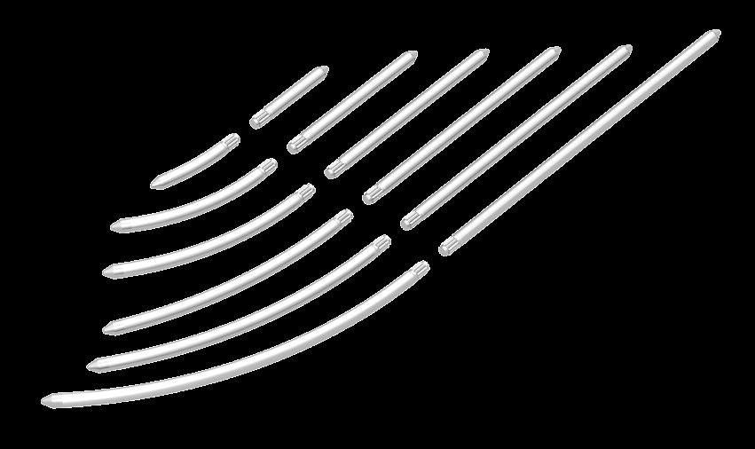
6 PRODUCT INFORMATION Implants The DIPLOMAT MIS system uses pedicle screws of the DIPLOMAT pedicle screw system. This allows the greatest possible selection of screws available on the market, even for minimally invasive procedures: Cannulated and fenestrated screws in 5.5 mm, 6.5 mm, 7.5 mm, 8.5 mm and 9.5 mm screw diameter. *Screws with a diameter of 4.5 mm are available only as cannulated screws! All screws are available in lengths ranging from 25 mm to 100 mm in relation to the screw diameter. Pedicle screws, without tulip, augmentable, polyaxial Fig. Art. No. Dimensions Incr. 1 AB to Ø 4.5x25 mm to 60 mm* 5 mm AB to Ø 5.5x25 mm to 60 mm 5 mm AB to Ø 6.5x25 mm to 65 mm 5 mm AB to Ø 7.5x25 mm to 75 mm 5 mm AB to Ø 7.5x80 mm to 100 mm 10 mm 2 AB to Ø 8.5x40 mm to 75 mm 5 mm AB to Ø 8.5x80 mm to 100 mm 10 mm AB to Ø 9.5x40 mm to 75 mm 5 mm AB to Ø 9.5x80 mm to 100 mm 10 mm Percutaneous tulip Fig. Art. No. Dimensions 3 AB Ø 12.5 mm x 150 mm Set screw Fig. Art. No. Dimensions 4 AB Set screw T30 MIS rods Fig. Art. No. Dimensions MIS rods Fig. Art. No. Dimensions AB Titanium MIS rod, straight, Ø 5.5x115 mm AB Titanium MIS rod, straight, Ø 5.5x120 mm AB Titanium MIS rod, straight, Ø 5.5x125 mm AB Titanium MIS rod, straight, Ø 5.5x130 mm AB Titanium MIS rod, straight, Ø 5.5x140 mm AB Titanium MIS rod, straight, Ø 5.5x150 mm AB Titanium MIS rod, curved, Ø 5.5x30 mm AB Titanium MIS rod, curved, Ø 5.5x35 mm AB Titanium MIS rod, curved, Ø 5.5x40 mm AB Titanium MIS rod, curved, Ø 5.5x45 mm AB Titanium MIS rod, curved, Ø 5.5x50 mm AB Titanium MIS rod, curved, Ø 5.5x55 mm AB Titanium MIS rod, curved, Ø 5.5x60 mm AB Titanium MIS rod, curved, Ø 5.5x65 mm 5 AB Titanium MIS rod, curved, Ø 5.5x70 mm AB Titanium MIS rod, curved, Ø 5.5x75 mm AB Titanium MIS rod, curved, Ø 5.5x80 mm AB Titanium MIS rod, curved, Ø 5.5x85 mm AB Titanium MIS rod, curved, Ø 5.5x90 mm AB Titanium MIS rod, curved, Ø 5.5x95 mm AB Titanium MIS rod, curved, Ø 5.5x100 mm AB Titanium MIS rod, curved, Ø 5.5x105 mm AB Titanium MIS rod, curved, Ø 5.5x110 mm AB Titanium MIS rod, curved, Ø 5.5x115 mm AB Titanium MIS rod, curved, Ø 5.5x120 mm AB Titanium MIS rod, curved, Ø 5.5x125 mm AB Titanium MIS rod, curved, Ø 5.5x130 mm AB Titanium MIS rod, curved, Ø 5.5x140 mm AB Titanium MIS rod, curved, Ø 5.5x150 mm 5 AB AB AB AB AB AB AB AB AB AB AB AB AB AB AB AB AB Titanium MIS rod, straight, Ø 5.5x30 mm Titanium MIS rod, straight, Ø 5.5x35 mm Titanium MIS rod, straight, Ø 5.5x40 mm Titanium MIS rod, straight, Ø 5.5x45 mm Titanium MIS rod, straight, Ø 5.5x50 mm Titanium MIS rod, straight, Ø 5.5x55 mm Titanium MIS rod, straight, Ø 5.5x60 mm Titanium MIS rod, straight, Ø 5.5x65 mm Titanium MIS rod, straight, Ø 5.5x70 mm Titanium MIS rod, straight, Ø 5.5x75 mm Titanium MIS rod, straight, Ø 5.5x80 mm Titanium MIS rod, straight, Ø 5.5x85 mm Titanium MIS rod, straight, Ø 5.5x90 mm Titanium MIS rod, straight, Ø 5.5x95 mm Titanium MIS rod, straight, Ø 5.5x100 mm Titanium MIS rod, straight, Ø 5.5x105 mm Titanium MIS rod, straight, Ø 5.5x110 mm Other consumables Fig. Art. No. Dimensions AC Guide wire for obturator Ø 1.8 mm 252 mm MP0058 Guide wire Ø 1.8 mm 500 mm, round 6 SM-SF0927 Cement cannula SM-IN0001 INTROX FIX-Cement with Mini Mixer 7 DBMNJ1106TL Bone access needle Some items are not for distribution outside EU. 6


7 DIPLOMAT


 20 AC0040 Cement delivery")
8 PRODUCT INFORMATION Instruments Fig. Art. No. Description AC05AY MIS Instrument tray 1 AC MIS Polyaxial screwdriver inner part AC MIS Forceps with handle 2 AC MIS Forceps - part 2 AC MIS Forceps - part 3 3 AC0103 MIS Dilator insert for tap 4 AC0104 AC0109 MIS Tap cannulated Ø 4.5 mm Ø 9.5 mm 5 AC0110 MIS Dilator inside 6 AC0111 MIS Dilator outside 7 AC0112 MIS Pedicle Awl cannulated 8 AC0113 MIS Screw length ruler AC MIS Rod gauge - part 1 9 AC MIS Rod gauge - part 2 10 AC0118 MIS Blade remover for percutaneus tulip 11 AC0119 MIS guide for tap remover 12 AC0121 MIS Tulip sleeve 13 AC0020 Counter torque pedicle screw 14 AC0018 Set screwdriver, intermediate 15 AC0017 Set screwdriver 16 AC0032 T-handle with torque limiter 11 Nm 17 AC0031 T-handle with ratchet 18 AC0022 Tulip adjuster 19 MP1031-A Combined compressor/distractor (optional) 20 AC0040 Cement delivery cannula (optional) Retractor AC06AY Retractor tray 21 AC0131 Retractor rack AC Adjustment unit 22 AC Adjustment key 23 AC0133 MIS arm Optional 24 AC0134 Screw to screw arm 25 AC0135 Medial arm 26 AC0136 Medial arm key 27 AC Blade 20 x 40 mm 28 AC Blade 20 x 60 mm 29 AC Blade 20 x 80 mm 30 AC Blade 20 x 100 mm


9 DIPLOMAT , 22 AND 23 ASSEMBLED OPTIONAL , 22, 25 AND 30 ASSEMBLED 20 9
10 PRODUCT INFORMATION Indications and contraindications, warnings Indications The system is indicated for stabilization of the spine until solid spinal fusion is achieved in patients with: Instability or malposition of the spine Fractures Tumors and spondylodiscitis Spondylolisthesis Disc prolapse Stenosis of the lumbar spine Disc resection Abnormal lordosis/kyphosis/scoliosis Degenerative segmental disease Osteoporosis Bone tumors (metastatic or primary) Revision surgery Postoperative or degenerative instability Rheumatic diseases with associated poor bone density or quality The system is furthermore indicated in situations where external immobilization by means of a plaster cast or splint is not possible. Medical conditions that could prevent successful implantation (e.g., obesity, mental illness, pregnancy, pediatric cases, patients in poor general health, lack of patient compliance) Cases not mentioned under indications Warnings The attending physician, who must be both trained and experienced in carrying out spinal interventions, is responsible for determining the indication, selecting the implant and performing the implantation. More information about application is available in the instructions for use accompanying the product. Contraindications Infectious processes in, on, or in adjacent regions of the spine Severe osteoporosis is a relative contraindication and may prevent adequate fixation of the spinal anchorage and thus exclude the use of this or other spinal instrumentation systems Surgery precluded due to the physical condition of the patient, e.g., fever or leukocytosis The use of different metals or components not belonging to the pedicle screw system is not permitted Patients whose tissue cover above the surgical site or whose bone mass or bone quality at the surgical site is inadequate Patients in whom placement of an implant would influence the anatomic structures or the anticipated physiological performance Systemic or metabolic diseases Allergy or intolerance to implant material Surgical conditions that rule out any potential benefit from spinal surgery (such as severe damage to bone structures at the implantation site, badly distorted anatomy due to anomalies) 10

11 DIPLOMAT Surgical technique 1 After positioning and draping the patient and setting up the image converter, the segment to be treated is defined. First, a bone access needle is placed under X-ray surveillance. Then the bone access needle is inserted according to the relevant pedicles visualized in the X-ray. 2 The bone access needle is used to open the pedicle and the mandrill is removed. The guide wire (MP0058) is first introduced into the bone access needle with the distal laser marking and under X-ray surveillance is advanced into the vertebral body in accordance with the desired screw length. 3 After removal of the bone access needle, the cut is extended slightly and the guide wire is used to put the inner blue plastic dilator (AC0110) for dilating the tissue in place up to the pedicle. 4 The outer dilator (AC0111), which is X-ray transparent, is placed over the inner dilator up to the pedicle for further dilation. 11
 is passed over the guide wire to the pedicle in order to open it up further. The pedicle awl has a depth stop at 15.")

.")

12 PRODUCT INFORMATION Surgical technique 5 In the next step, the first, inner dilator is removed, while the outer dilator remains in place as a soft-tissue protector and constitutes the working channel. The cannulated pedicle awl (AC0112) is passed over the guide wire to the pedicle in order to open it up further. The pedicle awl has a depth stop at 15.0 mm and is not advanced into the pedicle beyond this depth. Note For this and other maneuvers, the guide wire is secured from penetrating the anterior cortical bone, for example, with a clamp at the proximal end! 6 It is verified radiographically that the distal tip of the guidewire is seated at the exact place where later on the tip of the pedicle screw is to be seated. With the cannulated pedicle awl in the appropriate position, the screw length to be selected can be determined at the lower laser marking of the guide wire using the screw length ruler (AC0113). To this end, the ruler is placed on the pedicle awl handle and the guide wire is introduced into the guide groove of the ruler. The laser marking indicates the screw length. After the screw length is measured, the pedicle awl is carefully removed. When doing so, make sure that the guide wire remains in position and that the proximal end remains sterile and is not contaminated. 7 All DIPLOMAT pedicle screws are self-tapping. Nevertheless, tappers are available in the appropriate diameters, e.g. for sclerotic bones. The dilator insert for tappers (AC0103) is introduced into the outer dilator and is placed directly on the bone surface of the pedicle. The selected tapper is placed in the opened pedicle by means of the guide wire and the thread is cut. Depth marks on the tapper provide orientation about the depth. Notes The thread length on the tappers is 36 mm! The diameter of the tappers is 0.5 mm less than that of the screws! The tapper is then removed and the dilator insert is carefully removed. Make sure that the guide wire remains in position. The outer dilator continues to remain in position for soft-tissue protection. 12


13 DIPLOMAT 8 After the desired screw size has been verified, the percutaneous tulip is audibly clicked onto the pedicle screw located in the implant set. Caution Check that the tulip is securely fitted onto the screw by pulling on the tulip while holding the screw shaft. If the screw shank remains connected with the tulip, the connection is secure. Then connect the screw with the screwdriver (AC0101) and insert the pedicle screw. Using the polyaxial pedicle screwdriver AC0101 The instrument's locking mechanism has a built-in spring that upon detaching the pedicle screw is intended to provide clear feedback about whether the instrument was fully detached from the tulip. For this reason, when assembling the Torx drive, the screw head must be pushed forward and then screwed into the tulip. Caution Make sure that the Torx bit of the screwdriver is completely recessed in the screw head. Otherwise, there is a risk that the tulip will cant and jam with the screwdriver, possibly culminating in damage to the instrument. Press the screwdriver forward in the tulip and insert it completely into the Torx screw head. To tighten the screw, turn it clockwise. To loosen the screw, turn it counterclockwise. 13


14 PRODUCT INFORMATION Surgical technique 8a Optional augmentation Use augmentable DIPLOMAT screws together with low-viscosity bone cement for vertebroplasty. It is essential to read the instructions for use and the recommendations of the bone cement manufacturer prior to application! For optimal cement flow behavior, INTROX FIX-Cement with Mini Mixer (SM-IN0001) is highly recommendable in practice. Mix the cement as described in its instructions for use and fill it into the accompanying Luer- Lock syringes. For each pedicle screw, connect one cement delivery (AC0040) with the screw by driving the sleeve into the tulip up to the stop. You must also ensure that the tip of the guide sleeve sits inside the screw head. Remove the obturator from the cement cannula by turning it and connect the syringe to the cannula. Press cement into the cannula until cement emerges from the distal end and can be removed. Each cement delivery cannula holds a maximum of 2 ml of cement. Laser markings on the plunger indicate the volume of cement that has been applied. Distal marking: 0.62 ml Proximal marking: 1.30 ml The marking on the proximal sleeve indicates whether the cannula is seated correctly in the screw. It must be flush with the guide sleeve. Once the cement is ready for injection, insert the cannula through the cement delivery into the pedicle screw head and slowly press the cement through the screw into the vertebral body by means of the obturator under X-ray surveillance. Proximal marking on the sleeve indicator for correct positioning of the cannula in the screw Proximal marking: 1.30 ml Distal marking: 0.62 ml 14
 onto the polyaxial screw heads.")
. The distance is measured from tulip to tulip and does not include the excess length (Figure 9a).")
15 DIPLOMAT 9 After all the screws have been placed, the rod template (AC0117) can be used to determine the rod length. Insert the ball points of the template through the two outermost tulips (cranial and caudal) onto the polyaxial screw heads. If other tulips are located between the two outer tulips (more than one segment), they are carefully moved aside. The rod length is read on the upper scale of the ruler. Note The measured rod length is related to the functional rod length (see figure). The distance is measured from tulip to tulip and does not include the excess length (Figure 9a). If distraction is planned, a longer rod must be selected. Note When using precurved rods, after the set screws have been screwed in, crossing of the percutaneous tulips may occur in the proximal area. It is nearly impossible to use the MIS distractor/compressor! If distraction or compression maneuvers are desired, straight screws must be used. If needed, bending pliers can be used to slightly bend straight screws. Caution: Overcontouring does not allow the instrumentation to be locked securely and restricts the angulation of the tulip. Figure 9a Functional rod length 10 The desired rod is connected with the rod holder (AC0102) (see Figure 10b). To this end, the proximal end of the rod (pinion shape) is inserted into the distal receiving slot of the rod holder. The connection with the set screw at the handle end of the rod holder is then securely locked (turn clockwise). Figure 10a Assembly of the rod holder Figure 10b Connect the rod with the rod holder 15

.")
16 PRODUCT INFORMATION Surgical technique 11 The rod holder is used to introduce the rod through the first tulip and through the additional tulips using X-ray surveillance as needed. 12 To ensure that the rod has passed through the tulips properly, one of the tabs of the rod template can be introduced into the tulip up to the "150" marking. If the marking is flush with the proximal end of the tulip, the rod is in proper position (figure). Note Make sure that the rod extends past the two outermost tulips by approx. 5 mm and rests completely in the tulip. Otherwise the stability of the instrumentation may fail after surgery. 16
 are placed on the tulips.")
, a set screw is then picked up and screwed into the tulip.")

17 DIPLOMAT 13 Once the rod has been introduced through all of the tulips, the rod is placed in the final position of the tulips with the set screws. To this end, the safety sleeves (AC0121) are placed on the tulips. The sleeves prevent the tulips from spreading apart and keep the set screws from canting or becoming lost while they are screwed in. With the intermediate set screwdriver (AC0018), a set screw is then picked up and screwed into the tulip. The instrument has two laser markings related to the reduction height for the rod. A total of 17 mm reduction height is available. The set screw is placed in the correct final position when the marking above the 150 is flush with the proximal end of the tulip. (see cut-out). Cut-out: Laser marking must be flush with the safety sleeve after the set screw has been screwed in completely. 17

.")
18 PRODUCT INFORMATION Surgical technique 13a Optional Distraction and compression Before the set screws are definitively tightened using the torque limiter (AC0017 and AC0032), distraction or compression maneuvers can still be carried out. Tighten a set screw to create a stabilization point for the distraction. The set screw of the screw to be shifted should be loosened by a quarter rotation. The DIPLOMAT MIS retractor is assembled in accordance with the separate instructions for use. The two sleeves are pushed over the tulips to be distracted and compressed and are tilted upward. The distraction or compression is performed with the adjustment key (turn left or right). After the maneuver is completed, the torque key can be used to tighten the loose set screw in its final position and the distractor can be removed. Alternatively, unisegmental distraction/compression can also be performed with the combined compressor/distractor (MP1031-A). available as an option. Caution Ensure that all set screws have been completely reset and provisionally tightened. Otherwise, misalignment might occur! 14 Final tightening of the set screws Position the counter torque pedicle screw (AC0020) as an abutment onto the screw head either in a perpendicular position or parallel to the rod. Attach the T-handle with the 11 Nm torque limiter to the set screwdriver. The instrument assembly can be inserted through the counter torque into the drive of the locking screw. Ensure that the polyaxial screw head and rod are aligned perpendicularly to one another. Then tighten the set screw until a noticeable and audible click is felt and heard. This indicates that the required torque has been reached. Repeat this process for all the set screws. After tightening all the screws for the first time, tighten all of the set screws in order. Start with the caudal left screw of the construction and proceed clockwise in order to systematically re-tighten all set screws definitively. 18
 over the tulip up to the rod.")
 over the screw head.")

19 DIPLOMAT 15 Breaking off the screw tabs To break off the tabs of the percutaneous tulips, first introduce the guide instrument for tab remover (AC0119) over the tulip up to the rod. This instrument prevents the tulip from spreading when the tabs are broken off. Then place the tab remover (AC0118) over the screw head. Carefully move the tab remover back and forth from the lateral position to the medial position to break off the tab. The tabs remain in the instrument and can be released by moving a clamp distally, for example. 16 Final instrumentation 19

 6023 9166-0 Fax: +49 (0) 6023 9166-161 info@signus.")

20 NOTE: This document was written by the technical department at SIGNUS Medizintechnik GmbH. Despite being reviewed by trained personnel, the sole purpose of this brochure is to provide an explanation of the technical aspects of handling the product described. This document, in particular the description of the surgical procedure, should not be considered medical scientific literature. SIGNUS Medizintechnik GmbH Industriestr Alzenau / Germany Tel: +49 (0) Fax: +49 (0) info@signus.com SIGNUS Australia Pty Ltd Suite 5, Level 3, Building 1 20 Bridge street Pymble, NSW 2073 MOBIS II ST Transforaminal Lumbar Interbody Fusion TLIF Cage Phone: +61 (0) Fax: +61 (0) info@signus.com.au POSEIDON Distractible vertebral body replacement implant Thoracolumbar VBR OSIRION Ⅰ Intraoperative neurophysiological EMG monitoring system Intraoperative Neuromonitoring Rev / 00_ROW-AU
Valencia Pedicle Screw Surgical Technique
 Valencia Pedicle Screw Surgical Technique VALENCIA CIRCUIT TABLE OF CONTENTS Design Rationale Indications for Use Surgical Technique 1. Pedicle Preparation 2. Screw Insertion 3. Rod Placement 4. Locking
M.I.S. MAKE IT SMART IN ONE SYSTEM. Surgical Technique. Hip Knee Spine Navigation
 M.I.S. MAKE IT SMART IN ONE SYSTEM Surgical Technique Hip Knee Spine Navigation M.U.S.T. Mini Open Surgical Technique Hip Knee Spine Navigation 2 C O N T E N T S 1 INTRODUCTION 4 2 SURGICAL TECHNIQUE 5
Surgical Technique & Product Catalogue. Guide for Open & MIS Procedures
 Surgical Technique & Product Catalogue Guide for Open & MIS Procedures INTRODUCTION The VIPER Cortical Fix Fenestrated Screw System is the first pedicle screw implant to offer enhanced fixation in both
USS Variable Axis Screw
 USS Variable Axis Screw Polyaxial side-opening pedicle screw Surgical technique Original Instruments and Implants of the Association for the Study of Internal Fixation AO/ASIF USS Variable Axis Screw
EXCELLA ll. Spinal System
 EXCELLA ll Spinal System Excella II Spinal System INDICATIONS FOR USE The Innovasis Excella II Spinal System is intended for use in the non-cervical area of the spine. WARNING: The safety and effectiveness
LUMBAR POSTERIOR MINIMALLY INVASIVE SYSTEM. Surgical Technique
 LUMBAR POSTERIOR MINIMALLY INVASIVE SYSTEM Surgical Technique Joint Spine Sports Med M.U.S.T. Mini Open Surgical Technique Joint Spine Sports Med CAUTION Federal law (USA) restricts this device to sale
TSLP Thoracolumbar Spine Locking Plate
 Anterior thoracolumbar spine locking plate TSLP Thoracolumbar Spine Locking Plate Surgical Technique Image intensifier control This description alone does not provide sufficient background for direct use
Threshold Pedicular Fixation System Surgical Technique
 Threshold Pedicular Fixation System Surgical Technique Table of Contents Patient Preparation and Positioning... 2 Determining Incision Location... 3 Assembling the Cannulated Awl... 4 Guide Wire Placement...
Thoracolumbar Spine Locking Plate (TSLP) System. A low-profile plating system for anterior stabilization of the thoracic and lumbar spine.
 System. A low-profile plating system for anterior stabilization of the thoracic and lumbar spine.") Thoracolumbar Spine Locking Plate (TSLP) System. A low-profile plating system for anterior stabilization of the thoracic and lumbar spine. Technique Guide Instruments and implants approved by the AO Foundation
Thoracolumbar Spine Locking Plate (TSLP) System. A low-profile plating system for anterior stabilization of the thoracic and lumbar spine. Technique Guide Instruments and implants approved by the AO Foundation
Thunderbolt. surgical technique. MIS Pedicle Screw System. Where Nimble and Secure Intersect
 Thunderbolt TM MIS Pedicle Screw System Where Nimble and Secure Intersect surgical technique i www.choicespine.com System Features Dovetail set screw: Minimizes head splay and cross-threading Secure connection
USS II ILIO-SACRAL Modular System for Stable Fixation in the Sacrum and Illium
 USS II ILIO-SACRAL Modular System for Stable Fixation in the Sacrum and Illium Instruments and implants approved by the AO Foundation. This publication is not intended for distribution in the USA. TECHNIQUE
USS Variable Axis Screw (VAS) System. For posterior fixation of the lumbar spine.
 System. For posterior fixation of the lumbar spine.") USS Variable Axis Screw (VAS) System. For posterior fixation of the lumbar spine. Technique Guide Instruments and implants approved by the AO Foundation Table of Contents Introduction USS Variable Axis
USS Variable Axis Screw (VAS) System. For posterior fixation of the lumbar spine. Technique Guide Instruments and implants approved by the AO Foundation Table of Contents Introduction USS Variable Axis
SURGICAL TECHNIQUE. SECURIS Pedicle Screw System for Minimally Invasive Surgery. 2 I SECURIS Pedicle Screw System
 Surgical Technique e Guide SECURIS Pedicle Screw System for Minimally Invasive Surgery Securis Pedicle Screw System has been engineered to provide temporary posterior stabilization of the thoracolumbar
VECTRA-T SURGICAL TECHNIQUE. The Translational Anterior Cervical Palate System. This publication is not intended for distribution in the USA.
 VECTRA-T The Translational Anterior Cervical Palate System This publication is not intended for distribution in the USA. SURGICAL TECHNIQUE Image intensifier control This description alone does not provide
PERFORATED CLICK X Augmentable pedicle screws for osteoporotic bone
 PERFORATED CLICK X Augmentable pedicle screws for osteoporotic bone Instruments and implants approved by the AO Foundation. This publication is not intended for distribution in the USA. SURGICAL TECHNIQUE
Imola Lateral IBF System Surgical Technique
 Imola Lateral IBF System Surgical Technique IMOLA CIRCUIT TABLE OF CONTENTS Design Rationale Instructions for Use Surgical Technique 1. Table Mounting 2. Surgical Planning & Targeting 3. Access and Preparation
 Visit our website on www.biotech-medical.com The DLP - Dorso-Lumbar Polyaxial Screw System has been designed to address the pathologies of the thoracolumbar spine. The DLP System contains a wide range
XRL A modular expandable radiolucent vertebral body replacement system
 XRL A modular expandable radiolucent vertebral body replacement system This publication is not intended for distribution in the USA. SURGICAL TECHNIQUE Table of Contents Introduction XRL 2 AO Spine Principles
The Versatile Polyaxial Solution for the Universal Spine Systems. USS II Polyaxial. Surgical Technique
 The Versatile Polyaxial Solution for the Universal Spine Systems USS II Polyaxial Surgical Technique Image intensifier control This description alone does not provide sufficient background for direct use
LCP Medial Distal Tibia Plate, without Tab. The Low Profile Anatomic Fixation System with Angular Stability and Optimal Screw Orientation.
 LCP Medial Distal Tibia Plate, without Tab. The Low Profile Anatomic Fixation System with Angular Stability and Optimal Screw Orientation. Technique Guide LCP Small Fragment System Table of Contents Introduction
The Implant. (Klappen außen sind nur 192 mm breit!) Ordering information. You start we help with our clearly arranged Starter Kit:
 Ordering information. You start we help with our clearly arranged Starter Kit:") ATHLET PRODUCT INFORMATION The Implant 1 construct = 1 main body + 1 end body (Klappen außen sind nur 192 mm breit!) Latch mechanism for secure connection of the implant components Ordering information
ATHLET PRODUCT INFORMATION The Implant 1 construct = 1 main body + 1 end body (Klappen außen sind nur 192 mm breit!) Latch mechanism for secure connection of the implant components Ordering information
A U X I L I A R Y C O N N E C T O R S Surgical Technique
 A U X I L I A R Y C O N N E C T O R S Surgical Technique AUXILIARY CONNECTORS ISSYS LP Auxiliary Connectors The ISSYS LP auxiliary connectors were designed to provide medial-lateral variability for the
L-VARLOCK. Posterior Lumbar Cage with adjustable lordosis. S urgical T echnique
 L-VARLOCK Posterior Lumbar Cage with adjustable lordosis S urgical T echnique Introduction Designed and manufactured by KISCO International, L-VARLOCK cages are made of titanium alloy Ti 6AI 4V (standards
Cervical Solutions. Optio-C Anterior Cervical Plate. with Allograft/Autograft. Surgical Technique Guide
 Cervical Solutions Optio-C Anterior Cervical Plate with Allograft/Autograft Surgical Technique Guide 2 Optio-C Anterior Cervical Plate with Allograft/Autograft Surgical Technique Guide The Optio-C System
The Most Reliable Spinal Solution
 MFG : 09.02.20 REV : 1 4CIS VANE introduces you the reliable pedicle screw The Most Reliable Spinal Solution Non-slip threaded joint Ergonomic design Wedged trapezoid thread Superior locking mechanism
X-spine Surgical Technique
 X-spine Surgical Technique The X90 Pedicle Screw System Revolutionary Design and Function This document is intended exclusively for experts in the field, particularly physicians, and is not intended for
nvt Transforaminal Lumbar Interbody Fusion System
 nvt Transforaminal Lumbar Interbody Fusion System 1 IMPORTANT INFORMATION FOR PHYSICIANS, SURGEONS, AND/OR STAFF The nv a, nv p, and nv t are an intervertebral body fusion device used in the lumbar spine
Conventus CAGE PH Surgical Techniques
 Conventus CAGE PH Surgical Techniques Conventus Orthopaedics The Conventus CAGE PH (PH Cage) is a permanent implant comprised of an expandable scaffold, made from nitinol and titanium, which is deployed
Table of Contents.
 surgical technique The Ambassador TM Anterior Cervical Plate System is a versatile system of implants and instruments with a variety of sizes to provide optimal anatomic compatibility. The integrated cam
Technique Guide. MATRIX Spine System MIS Instrumentation. The total solution for simple and complex spine pathology.
 Technique Guide MATRIX Spine System MIS Instrumentation. The total solution for simple and complex spine pathology. Table of Contents Introduction MATRIX Spine System MIS Instrumentation 2 AO Principles
operative technique Universal Application
 operative technique Universal Application Introduction Introduction Building upon the design rationale of the Xia Spinal System, the new Xia Spinal System represents the latest advancement in spinal implant
Y o u r Id e a s En g i n e e r e d t o Li f e
 ISSYS LP Spinal Fixation System Surgical Guide Y o u r Id e a s En g i n e e r e d t o Li f e In t r o d u c t i o n ISSYS LP Sp i n a l Fixation System The foundation of the ISSYS LP Spinal Fixation System
SYNEX The vertebral body replacement with ratchet mechanism
 SYNEX The vertebral body replacement with ratchet mechanism Instruments and implants approved by the AO Foundation. This publication is not intended for distribution in the USA. SURGICAL TECHNIQUE Image
Technique Guide. ArcoFix. Anterior-only reduction plate.
 Technique Guide ArcoFix. Anterior-only reduction plate. Table of Contents Introduction ArcoFix 2 AO Principles 4 Indications and Contraindications 5 Surgical Technique Preoperative Planning 6 Insert ArcoFix
nvp Posterior Lumbar Interbody Fusion System
 nvp Posterior Lumbar Interbody Fusion System 1 IMPORTANT INFORMATION FOR PHYSICIANS, SURGEONS, AND/OR STAFF The nv a, nv p, and nv t are an intervertebral body fusion device used in the lumbar spine following
TECHNICAL BROCHURE. Capture Facet Fixation System
 TECHNICAL BROCHURE Capture Facet Fixation System Table of Contents Product Overview...2 Instruments...4 Capture Facet Screw Surgical Technique Patient Preparation and Positioning...6 Guide Pin Placement...7
ONE SYSTEM, MULTIPLE OPTIONS. Surgical Technique. Hip Knee Spine Navigation
 ONE SYSTEM, MULTIPLE OPTIONS Surgical Technique Hip Knee Spine Navigation MUST MINI Surgical Technique Hip Knee Spine Navigation INTRODUCTION The M.U.S.T. Mini posterior cervical screw system is a modular
TiLock XT Minimally Invasive Surgery (MIS) Pedicle Screw System
 Pedicle Screw System") Minimally Invasive Surgery (MIS) Pedicle Screw System Surgical Technique Guide 2 Minimally Invasive Surgery (MIS) Pedicle Screw System The Genesys Spine Minimally Invasive Surgery (MIS) Pedicle Screw System
Minimally Invasive Surgery (MIS) Pedicle Screw System Surgical Technique Guide 2 Minimally Invasive Surgery (MIS) Pedicle Screw System The Genesys Spine Minimally Invasive Surgery (MIS) Pedicle Screw System
LCP Distal Tibia Plate
 Surgical Technique LCP Locking Compression Plate Original Instruments and Implants of the Association for the Study of Internal Fixation AO/ASIF Table of contents Indications 3 Implants/Instruments 5 Surgical
nva Anterior Lumbar Interbody Fusion System
 nva Anterior Lumbar Interbody Fusion System 1 IMPORTANT INFORMATION FOR PHYSICIANS, SURGEONS, AND/OR STAFF The nv a, nv p, and nv t are an intervertebral body fusion device used in the lumbar spine following
TELEFIX SURGICAL TECHNIQUE. Implant system for the anterior stabilization of the thoracolumbar spine
 TELEFIX Implant system for the anterior stabilization of the thoracolumbar spine Instruments and implants approved by the AO Foundation. This publication is not intended for distribution in the USA. SURGICAL
MEDACTA UNCONSTRAINED SCREW TECHNOLOGY - REDUCTION SCREWS. Surgical Technique. Hip Knee Spine Navigation
 .U.S.T. MEDACTA UNCONSTRAINED SCREW TECHNOLOGY - REDUCTION SCREWS Hip Knee Spine Navigation M.U.S.T. Hip Knee Spine Navigation INTRODUCTION The Medacta Unconstrained Screw Technology [M.U.S.T.] Pedicle
Ballista Percutaneous Screw Placement System. Surgical Technique
 Ballista Percutaneous Screw Placement System Surgical Technique Contents Introduction... Page 1 Features And Benefits... Page 2 Implants... Page 3 Instruments... Page 4 Surgical Technique... Page 8 Indications
TiLock XT Minimally Invasive Surgery (MIS) Pedicle Screw System
 Pedicle Screw System") TiLock XT Minimally Invasive Surgery (MIS) Pedicle Screw System The Genesys Spine TiLock XT Minimally Invasive Surgery (MIS) Pedicle Screw System consists of rods (straight and curved), lock screws, and
TiLock XT Minimally Invasive Surgery (MIS) Pedicle Screw System The Genesys Spine TiLock XT Minimally Invasive Surgery (MIS) Pedicle Screw System consists of rods (straight and curved), lock screws, and
SURGICAL TECHNIQUE GUIDE TRESTLE. Anterior Cervical Plating System
 SURGICAL TECHNIQUE GUIDE TRESTLE Anterior Cervical Plating System 2 SURGICAL TECHNIQUE GUIDE SURGICAL TECHNIQUE GUIDE System Features Large window enables visualization of graft site and end plates Screw
WINSTA-C. Clavicle Plating System
 Clavicle Plating System Clinical Advisor Michael Kurer FRCS FRCS (Orth) Consultant Orthopaedic and Shoulder Surgeon North Middlesex University Hospital NHS Trust Table of Contents Introduction Indication
Surgical technique. synex. The vertebral body replacement with ratchet mechanism.
 Surgical technique synex. The vertebral body replacement with ratchet mechanism. Table of contents Indications and contraindications 2 Implants 3 Surgical technique 4 Cleaning of instruments 10 Optional
Technique Guide. 3.5 mm LCP Low Bend Medial Distal Tibia Plates. Part of the Synthes locking compression plate (LCP) system.
 system.") Technique Guide 3.5 mm LCP Low Bend Medial Distal Tibia Plates. Part of the Synthes locking compression plate (LCP) system. Table of Contents Introduction 3.5 mm LCP Low Bend Medial Distal Tibia Plates
Technique Guide 3.5 mm LCP Low Bend Medial Distal Tibia Plates. Part of the Synthes locking compression plate (LCP) system. Table of Contents Introduction 3.5 mm LCP Low Bend Medial Distal Tibia Plates
Surgical Technique. CONQUEST FN Femoral Neck Fracture System
 Surgical Technique CONQUEST FN Femoral Neck Fracture System Table of Contents Introduction... 3 Indications... 3 Product Overview... 4 Surgical Technique... 5 Patient Positioning... 5 Reduce the Fracture...
HydraLok. Operative Technique. Polyaxial Pedicle Screw System
 HydraLok Operative Technique Polyaxial Pedicle Screw System Table of Contents Introduction...1 OPERATIVE TECHNIQUE OVERVIEW...2 DETAILED OPERATIVE TECHNIQUE...4 LOCATE AND PREPARE THE PEDICLE...4 PROBE
Ballista Percutaneous Screw Placement System
 Surgical Technique Ballista Percutaneous Screw Placement System A Minimally Invasive Approach for Posterior Spinal Surgery True percutaneous system Helical Flange locking mechanism Contents Introduction...
EXCELLA MIS. Spinal System
 EXCELLA MIS Spinal System Excella MIS Spinal System INDICATIONS FOR USE The Innovasis Excella MIS Spinal System is intended for use in the non-cervical area of the spine. WARNING: The safety and effectiveness
EXACTECH SPINE. Operative Technique. Cervical Spacer System. Surgeon focused. Patient driven. TM
 EXACTECH SPINE Operative Technique Cervical Spacer System Surgeon focused. Patient driven. TM ACAPELLA ONE Acapella One Cervical Spacer System is an anterior cervical discectomy and fusion device with
Replacement Device A modular expandable radiolucent vertebral body replacement system
 XRL Vertebral Body Replacement Device A modular expandable radiolucent vertebral body replacement system SURGICAL TECHNIQUE TABLE OF CONTENTS Introduction XRL System 2 AO Principles 5 Indications and Contraindications
AxSOS Locking Plate System
 AxSOS Locking Plate System Operative Technique Small Fragment Basic Fragment 1 2 Contents Page 1. Introduction 4 2. Features & Benefits 5 4 and 5mm Compression Plates 5 Reconstruction and 1/3 Tubular Locking
TABLE OF CONTENTS. 2 (8144 Rev 2)
") 1 (8144 Rev 2) TABLE OF CONTENTS Introduction Conventus CAGE TM - Proximal Humerus...3 Indications and Contraindications...4 Surgical Summary...5 Patient Positioning & Approach...6 Surgical Technique Plate
1 (8144 Rev 2) TABLE OF CONTENTS Introduction Conventus CAGE TM - Proximal Humerus...3 Indications and Contraindications...4 Surgical Summary...5 Patient Positioning & Approach...6 Surgical Technique Plate
CSLP-Cervical Spine Locking Plate
 For anterior, cervical fixation CSLP-Cervical Spine Locking Plate Surgical Technique Image intensifier control This description alone does not provide sufficient background for direct use of DePuy Synthes
L8 Spine System SURGICAL TECHNIQUE. Add: No.1-8, Tianshan Road, Xinbei District, Changzhou, Jiangsu, China
 Add: No.-8, Tianshan Road, Xinbei District, Changzhou, Jiangsu, China 23022 Tel: 0086 59 8595556 Fax: 0086 59 859555 Http://www.kanghui.com Add: F25, Shanghai International Pharmaceutical Trad & Exhibition
Ref: Q400-09T1 EBI Spine. September 05/VS02. c/o BIOMET Spain Orthopaedics, S.L.
 Ref: Q400-09T1 EBI Spine. September 05/VS02 c/o BIOMET Spain Orthopaedics, S.L. www.ebimedical.com EBI Omega 21 TM LP Since its introduction in 1996, and with thousands of patients treated so far, the
BAK/C Cervical Anterior Interbody Fusion System
 Surgical Technique BAK/C Cervical Anterior Interbody Fusion System The Comfortable Choice for Cervical Fusion BAK/C Cervical Surgical Technique 1 The BAK/C Cervical Fusion System is an alternative to conventional
Technique Guide. 3.5 mm LCP Low Bend Medial Distal Tibia Plate Aiming Instruments. Part of the 3.5 mm LCP Percutaneous Instrument System.
 Technique Guide 3.5 mm LCP Low Bend Medial Distal Tibia Plate Aiming Instruments. Part of the 3.5 mm LCP Percutaneous Instrument System. Table of Contents Introduction 3.5 mm LCP Low Bend Medial Distal
MATRIX Spine System Deformity
 A Solution for Simple and Complex Spine Pathology MATRIX Spine System Deformity Surgical Technique Image intensifier control This description alone does not provide sufficient background for direct use
Zimmer Anterior Buttress Plate System. Surgical Technique
 Zimmer Anterior Buttress Plate System Surgical Technique 2 Zimmer Anterior Buttress Plate System Surgical Technique Zimmer Anterior Buttress Plate System Surgical Technique Description, Indications & Contraindications...
Zimmer Small Fragment Universal Locking System. Surgical Technique
 Zimmer Small Fragment Universal Locking System Surgical Technique Zimmer Small Fragment Universal Locking System 1 Zimmer Small Fragment Universal Locking System Surgical Technique Table of Contents Introduction
NCB Distal Femur System. Surgical Technique
 NCB Distal Femur System Surgical Technique NCB Distal Femur System Surgical Technique 3 Surgical Technique NCB Distal Femur System Table of Contents Introduction 4 Indications 8 Preoperative Planning
EXPEDIUM VERSE Spinal System
 EXPEDIUM VERSE Spinal System SYSTEM GUIDE CONTENTS 1. PRODUCT OVERVIEW 1 FEATURES AND BENEFITS 1 IMPLANT DESIGN 5 INSTRUMENT DESIGN AND SET CONFIGURATION 6 SET CONTENTS 7 2. SURGICAL TECHNIQUE 9 SCREW
Technique Guide. USS Fracture MIS. The minimally invasive Schanz Screw system for complete spinal fracture reduction.
 Technique Guide USS Fracture MIS. The minimally invasive Schanz Screw system for complete spinal fracture reduction. Image intensifier control Warning This description alone does not provide sufficient
Advantage ALIF. Keith Shevlin Managing Director
 Advantage ALIF Unit 10, 9-11 Myrtle Street, Crows Nest NSW 2065 Keith Shevlin Managing Director keithshevlin@precisionsurgical.com.au Advantage ALIF Introduction & Indications for Use 1 Surgical Technique
.U.S.T. MINI OPEN. Surgical Technique LUMBAR POSTERIOR MINIMALLY INVASIVE SYSTEM. Hip Knee Spine Navigation
 .U.S.T. MINI OPEN LUMBAR POSTERIOR MINIMALLY INVASIVE SYSTEM Surgical Technique Hip Knee Spine Navigation M.U.S.T. Mini Open Surgical Technique Hip Knee Spine Navigation CAUTION Federal law (USA) restricts
VIPER Cortical Fix Fenestrated Screw System. Surgical Technique for OPEN & MIS Procedures
 VIPER Cortical Fix Fenestrated Screw System Surgical Technique for OPEN & MIS Procedures Image intensifier control This description alone does not provide sufficient background for direct use of DePuy
Augmentable Pedicle Screws for Osteoporotic Bone. Perforated Click X. Surgical Technique
 Augmentable Pedicle Screws for Osteoporotic Bone Perforated Click X Surgical Technique Image intensifier control This description alone does not provide sufficient background for direct use of DePuy Synthes
EIT TLIF Cage. For Natural Bone Ingrowth with EIT Cellular Titanium
 EIT TLIF Cage For Natural Bone Ingrowth with EIT Cellular Titanium EIT TLIF Cage Surgical Technique EIT Cellular Titanium provides active fusion area» ~ 80% porosity» ~ 650 µm diamond pore size» open interconnected
Instrument and Implant for wrist fracture
 Instrument and Implant for wrist fracture Jansri Janpanya Product specialist The Bangkok Unitrade Co,.ltd. Objectives Type of LCP for distal radius Fx. The new LCP design for distal radius Fx. Have knowledge
100 Interpace Parkway Parsippany, NJ
 100 Interpace Parkway Parsippany, NJ 07054 www.biometspine.com 800-526-2579 All trademarks are the property of Biomet, Inc. or one of its subsidiaries, unless otherwise indicated. Rx Only. 2009 EBI, LLC.
O PE RATIV E TE C HN IQ U E. Minimally Invasive Posterior Fixation
 O PE RATIV E TE C HN IQ U E TM Minimally Invasive Posterior Fixation Table of Contents 1 PRE-OPERATIVE PLANNING Patient Positioning Pedicle Identification and Incision Planning 4 OPERATIVE TECHNIQUE Incision
The vertebral body replacement with ratchet mechanism. Synex. Surgical Technique
 The vertebral body replacement with ratchet mechanism Synex Surgical Technique Image intensifier control This description alone does not provide sufficient background for direct use of DePuy Synthes products.
Handling instructions. USS Low Profile. Thoracolumbar posterior fixation system.
 Handling instructions USS Low Profile. Thoracolumbar posterior fixation system. U Table of contents Introduction Indications and contraindications 3 USS Low Profile implants 4 Handling implants with stick
SAMSON. Expandable Vertebral Body Replacement
 SAMSON Expandable Vertebral Body Replacement System SAMSON is an expandable vertebral body replacement system which is used for the anterior stabilisation of the spinal column, from the upper thoracic
Technique Guide. LCP Proximal Femoral Hook Plate 4.5/5.0. Part of the LCP Periarticular Plating System.
 Technique Guide LCP Proximal Femoral Hook Plate 4.5/5.0. Part of the LCP Periarticular Plating System. Table of Contents Introduction Features and Benefits 2 AO ASIF Principles 4 Indications 5 Surgical
ACP. Anterior Cervical Plate System SURGICAL TECHNIQUE
 ACP Anterior Cervical Plate System SURGICAL TECHNIQUE ACP TABLE OF CONTENTS INTRODUCTION 4 INDICATIONS AND CONTRAINDICATIONS 5 WARNINGS AND PRECAUTIONS 6 IMPLANT DESCRIPTION 7 INSTRUMENTS 10 SURGICAL
AccuVision Minimally Invasive Spinal Exposure System
 Surgical Technique AccuVision Minimally Invasive Spinal Exposure System Working Beyond the Tube Lighted blades for superior viewing Maximum stabilization Contents Introduction... Page 1 Features and Benefits...
Surgical Technique. Targeter Systems Overview
 Surgical Technique Targeter Systems Overview PERI-LOC Locked Plating System Targeter Systems Overview Table of contents Product overview... 2 Introduction... 2 Indications... 2 Design features and benefits...
LCP Medial Proximal Tibial Plate 3.5. Part of the Synthes small fragment Locking Compression Plate (LCP) system.
 system.") LCP Medial Proximal Tibial Plate 3.5. Part of the Synthes small fragment Locking Compression Plate (LCP) system. Technique Guide This publication is not intended for distribution in the USA. Instruments
LCP Medial Proximal Tibial Plate 3.5. Part of the Synthes small fragment Locking Compression Plate (LCP) system. Technique Guide This publication is not intended for distribution in the USA. Instruments
PACH PLATE 2 OR 4 HOLE FIXATION
 2 OR 4 HOLE FIXATION The Science of Fusion PACH_v6.indd 1 6/03/2015 7:10 am PACH Plate Design Rationale The PACH Plate has been designed to be used as an anterior or lateral fixation plate for the thoracolumbar,
MODULAR DESIGN OFFERS FREEDOM OF CHOICE. Surgical Technique
 MODULAR DESIGN OFFERS FREEDOM OF CHOICE Surgical Technique Joint Spine Sports Med MectaLIF Anterior Surgical Technique 2 INDEX 1. INTRODUCTION 4 1.1 Material & Marker 5 2. INDICATIONS 5 3. CONTRAINDICATIONS
Headless Compession Screw 2.5 / 3.0
 SURGICAL TECHNIQUE Headless Compession Screw 2.5 / 3.0 Titanium or Stainless Steel Cannulated Headless Design Multiple Thread Options Torx Driver Sterile and Non-Sterile Options Simple Instrumentation
Technique Guide. Universal Spinal System (USS). Designed to achieve the goals of scoliosis surgery.
. Designed to achieve the goals of scoliosis surgery.") Technique Guide Universal Spinal System (USS). Designed to achieve the goals of scoliosis surgery. Table of Contents Introduction Universal Spinal System 2 AO ASIF Principles of Internal Fixation 3 Indications
Technique Guide Universal Spinal System (USS). Designed to achieve the goals of scoliosis surgery. Table of Contents Introduction Universal Spinal System 2 AO ASIF Principles of Internal Fixation 3 Indications
Technique Guide. Insight Retractor. Minimal invasive access system to the posterior thoracolumbar spine.
 Technique Guide Insight Retractor. Minimal invasive access system to the posterior thoracolumbar spine. Table of Contents Introduction Insight Retractor 2 AO Principles 4 Indications and Contraindications
Zimmer Trabecular Metal Ankle Interpositional Spacer and Trabecular Metal Ankle Fusion Spacer
 Zimmer Trabecular Metal Ankle Interpositional Spacer and Trabecular Metal Ankle Fusion Spacer Surgical Technique 2 Zimmer Trabecular Metal Ankle Interpositional Spacer and Trabecular Metal Ankle Fusion
Royal Oak Cervical Plate System
 Royal Oak Cervical Plate System Manufactured by Nexxt Spine, Inc. Royal Oak Cervical Plate System INTRODUCTION FEATURES AND BENEFITS Table of Contents SURGICAL TECHNIQUE Step 1. Patient Positioning Step
TM TM Surgical Technique
 TM TM Surgical Technique TABLE OF CONTENTS Reli SP Spinous Plating System Overview Device Description Implant Features Indications Instruments Access Instruments Preparation Instruments Insertion Instruments
Interbody fusion cage for the transforaminal approach. Travios. Surgical Technique
 Interbody fusion cage for the transforaminal approach Travios Surgical Technique Image intensifier control This description alone does not provide sufficient background for direct use of DePuy Synthes
3. Insert Tocar Sleeves Insert the NCB tissue protection sleeve assembly 1.6 to 10mm through a skin incision (Fig. 38).
.") NCB Proximal Humerus Plating System Surgical Technique 19 2. Temporary Plate Fixation The plate can be temporary fixed to the bone with 1.6mm K-wire through the proximal cannulated fixation screw of the
NCB Proximal Humerus Plating System Surgical Technique 19 2. Temporary Plate Fixation The plate can be temporary fixed to the bone with 1.6mm K-wire through the proximal cannulated fixation screw of the
Headless Compession Screw 4.5 / 6.5 SURGICAL TECHNIQUE. Titanium or Stainless Steel. Cannulated Headless Design. Multiple Thread Options.
 Headless Compession Screw SURGICAL TECHNIQUE 4.5 / 6.5 Titanium or Stainless Steel Cannulated Headless Design Multiple Thread Options Torx Driver Sterile and Non-Sterile Options Simple Instrumentation
Surgical Technique. Occipito-Cervico-Thoracic System
 OASYS Surgical Technique Occipito-Cervico-Thoracic System System Overview The OASYS Occipito-Cervico-Thoracic System was developed to provide the surgeon with versatility for the treatment of pathologies
PediLoc 3.5mm and 4.5mm Contour Femur Plate Surgical Technique
 PediLoc 3.5mm and 4.5mm Contour Femur Plate Surgical Technique Surgical Technique Contour Femur Plate The technique description herein is made available to the healthcare professional to illustrate the
VLIFT System Overview. Vertebral Body Replacement System
 VLIFT System Overview Vertebral Body Replacement System VLIFT System System Description The VLIFT Vertebral Body Replacement System consists of a Distractible In Situ (DIS) implant, which enables the surgeon
ONE SYSTEM, MULTIPLE OPTIONS. Surgical Technique
 ONE SYSTEM, MULTIPLE OPTIONS Surgical Technique Joint Spine Sports Med M.U.S.T. Mini Surgical Technique 2 INDEX 1. INTRODUCTION 4 1.1 Indications 4 1.2 Contraindications 4 1.3 Pre-Operative Planning 5
Technique Guide. C1/C2 Access System. Percutaneous transarticular screw fixation.
 Technique Guide C1/C2 Access System. Percutaneous transarticular screw fixation. C1/C2 Access System Table of Contents General introduction 2 Indications/Contraindications 2 Image intensifier-assisted