Surgical Technique. LLIF Procedure. Lateral Lumbar Interbody Fusion. with MARS 3V & TransContinental
|
|
|
- Oliver Griffith
- 5 years ago
- Views:
Transcription


1 Surgical Technique LLIF Procedure Lateral Lumbar Interbody Fusion with MARS 3V & TransContinental


2 At Globus, we move with a sense of urgency to deliver innovations that improve the quality of life for patients with spinal disorders. We are inspired by the needs of these patients and also the needs of the surgeons and health care providers who treat them. This passion combined with Globus world class engineering transforms clinical insights into tangible spine care solutions. We are driven to provide the highest quality products to improve the techniques and outcomes of spine surgery so patients can resume their lives as quickly as possible. We extend our reach beyond our world class implants, instrumentation, and service by partnering with researchers and educators to advance the science and knowledge of spine care. The energy and enthusiasm each of us bring everyday to Globus is palpable. We are constantly in the pursuit of better patient care and understand that speed is critical because life cannot wait.
, Menard developed a procedure that allowed greater exposure to the lateral aspect of the spine.")


3 LLIF Lateral Lumbar Interbody Fusion The use of a lateral approach to access the thoracolumbar spine has been well documented in literature. In the late 9th century (894), Menard developed a procedure that allowed greater exposure to the lateral aspect of the spine. Capener, in 954, built on Menard s advances for the treatment of Pott disease (tuberculosis of the spine)., However, their procedures had limitations. During the past 35 years, surgeons have continued to develop the lateral technique. In 976 Fraser et al. described a muscle splitting approach to the lumbosacral spine. The exposure gained with this retroperitoneal technique offered successful access to the mid-lumbar and lumbosacral spine. 3 O Brien analyzed his many patients that underwent a leftsided, retroperitoneal approach. The benefit of this was avoidance of canal trauma and elimination of motion by using a large graft. 4 McAfee et al. presented the first clinical series investigating the use of the lateral retroperitoneal approach for fusion from L-L5, reporting an overall lower morbidity comparable to traditional approaches. 5 Building on this, Bertagnoli developed the anterolateral transpsoatic approach for accessing the lumbar disc while avoiding disruption to the posterior elements. 6 Today, Globus has refined the lateral approach with the introduction of MarS 3V and TransContinental. Ménard V: Causes de la paraplégie dans le mal de Pott. Rev Orthop: 47 64, 894. Capener N: The evolution of lateral rhacotomy. J Bone Joint Surg Br 36: 73-79, Fraser RD, Gogan WJ. A Modified Muscle-Splitting Approach to the Lumbosacral Spine. Spine 7(8): 943-8, Kozak J, O Brien J. Simultaneous Combined Anterior and Posterior Fusion. An Independent Analysis of a Treatment for the Disabled Low-Back Pain Patient Spine 5(4): 3-38, McAfee P et al. Minimally Invasive Anterior Retroperitoneal Approach to the Lumbar Spine: Emphasis on the Lateral BAK. Spine 3(3): , Bertagnoli R, Vazquez RJ. The Anterolateral TransPsoactic Approach(ALPA): a new technique for implanting prosthetic disc-nucleus devices. J Spinal Disord Tech 6(4): , 003. LLIF Procedure LLIF Procedure

4 LLIF lateral lumbar interbody fusion The MIS lateral approach has been refined with the combination of the MARS 3V retractor and the TransContinental spacer system. MARS 3V is a versatile and variable vision system that gives unprecedented control of tissue retraction during the entire procedure. TransContinental is a comprehensive spacer system with extensive instrumentation. MARS 3V The MARS 3V Retractor provides the versatility, stability, and precision required to access hard-to-reach disc spaces. Independent blade retraction Individual blade angulation up to 0 Lightweight, aluminum components for radiolucency Illumination system fits within blade walls for less bulk TransContinental The TransContinental System is ideal for a minimally invasive approach to help preserve patient anatomy. Self-distracting leading edge for ease of insertion Radiographic positioning markers for implant placement and orientation Comprehensive disc preparation instrumentation Trial length indicators provide accurate length assessment on fluoroscopy Large surface area with pyramidal teeth for maximum engagement Large single graft window for solid fusion mass Leading edge self-distracts on insertion

5 Contents Distinguishing Characteristics MARS 3V Retractor Overview 4 Implant Overview 5 Instrument Overview 6 Surgical Technique. Patient Preparation 6. Initial Dilator Insertion 8 3. Retractor Insertion 9 4. Disc Preparation 5 5. Interbody Insertion 6 Using the Implant Insertion Tool 7 Final Position 8 TransContinental Implant Set 30 MARS 3V Retractor Set 3 MARS Instrument II Set 34 Anterior Disc Prep I Instrument Set 36 Anterior Disc Prep II Instrument Set 38 Lateral Disc Prep Instrument Set 40 TransContinental Insertion Instruments Set 4 Lateral Angled Disc Prep Instrument Set 44 TransContinental Angled Trials Set 46 TransContinental 6mm Wide Implant Set 48 Bayonetted Disc Prep Instrument Set 49 TransContinental mm Implant Set 50 TransContinental 0 Lordotic Implant Set 5 TransContinental Coronal Tapered Implant Set 54 Important Information 56 The Surgical Technique shown is for illustrative purposes only. The technique(s) actually employed in each case always depends on the medical judgment of the surgeon exercised before and during surgery as to the best mode of treatment for each patient. Additionally, as instruments may occasionally be updated, the instruments depicted in this Surgical Technique may not be exactly the same as the instruments currently available. Please consult with your sales representative or contact Globus directly for more information. LLIF Procedure 3


6 mars 3v retractor overview Guided Light Source Low-Profile 8mm Inner Diameter Blade Lock Extra Wide Cephalad-Caudad Blades Individual Blade Angulation Knob Radiolucent Arm Retractor Center Fixation Mount Independent Blade Retraction Knob Posterior Blade Fixation Mount 4

7 implant overview TransContinental Spacer Self-distracting leading edge Large single chamber for bone graft material Five axial footprints Three sagittal profiles (0, 6 and 0 Lordotic) TransContinental Instrumentation MIS compatible system Each trial provides precise length measurements Holder with sleeve eliminates challenges with implant disengagement Heights of 7 7 mm in mm increments Pyramidal teeth resist migration Height Lordosis mm or 8mm 60mm 6mm mm or 8mm 35mm 55mm 6mm mm or 8mm 30mm 50mm 6mm mm or 8mm 5mm 45mm 6mm mm, 8mm or 6mm 0mm 40mm LLIF Procedure 5

8 instrument Overview Access Instruments K-Wire Gripper K-Wire, 350mm S Fluoro Modulator Incision Locator Initial Dilator Holder Cannula A Cannula B Cannula C Cannula D


9 Retractor Assembly Retractor Blades Length Posterior Blade CC Blade 40mm mm mm mm mm mm mm mm mm mm mm mm mm mm Posterior Blade CC Blade Retractor 3 Blade Frame Table Clamp Articulating Arm Assembly LLIF Procedure 7


10 Retractor Instruments Suction mm Socket Driver Frame Handle Hook and Latch Driver Shim Tool Docking Pin Tool Disc Shim Tool Docking Pin Sleeve


11 Light Components MIS Illumination System S Fiber Optic Cord Adapter, ACMI Adapter, Wolf Adapter, Olympus Adapter, Storz LLIF Procedure 9
12 Disc Prep Instruments Bayonetted Annulotomy Knife S Cobb Elevator, Straight, 0mm Cobb Elevator, Straight, 0mm Rasp Disc Rotary Cutter Disc Box Cutter

13 Disc Prep Instruments (cont'd) Thin Rasp, x0mm Cobb, 7 Up-Angled, 0mm Cobb, 7 Up-Angled, 0mm Kerrison, 4mm 65.0 Kerrison, 6mm Disc Rongeur, 4mm Disc Rongeur, 4mm, Up Biting Disc Rongeur, 6mm LLIF Procedure
14 Scrapers Height Part Number 7mm mm mm mm mm mm Curettes Cobb Elevator, Angled, 8mm 65.0 Ring Curette, 0mm Ring Curette, 5mm 65.40
15 Curettes (cont'd) Bone Curette, 7.5 x.5mm, Straight Bone Curette, 7.5 x.5mm, Up-Angled Ring Curette, 0mm, Straight Ring Curette, 0mm, 7 Up-Angled Cup Curette, 6.5 x 9.5mm, Straight Cup Curette, 6.5 x 9.5mm, 5 Up-Angled Cup Curette, 6.5 x 9.5mm, 90 Down-Angled LLIF Procedure 3


16 Handles T-Handle L-Handle Insertion Instruments Trial, Parallel Trial, Lordotic Trials Height Parallel Lordotic 6 5mm mm mm mm mm mm mm
17 Insertion Instruments (cont'd) Slide Hammer, Long Implant Insertion Tool Insertion Sleeve Implant Insertion Tool , Insertion Sleeve (Assembled) Implant Positioner LLIF Procedure 5

 Just beneath the iliac crest; () Over the")

18 LLIF surgical technique Step Patient Preparation Patient Positioning The patient is placed on a flexible surgical table in a true 90 right lateral decubitus position so that the iliac crest is just over the table break, as shown below. The patient is then secured to the table at the following locations: () Just beneath the iliac crest; () Over the thoracic region, just under the shoulder; (3) From the back of the table, over the ankle, and (4) past the knee to the front of the table. The table should be flexed to open the interval between the th rib and iliac crest, and provide direct access to the disc space as shown below. Patient positioning 4 3 Patient secured to table Table flexed 6


19 X-Ray Confirmation Fluoroscopy is used to ensure that the spine is oriented in a true lateral position. The table should be adjusted so that the C-arm provides true AP images when at 0 and true lateral images at 90. Lateral image AP image Incision Location The operative area is carefully cleaned and the Incision Locator is used under fluoroscopy to identify the middle of the disc space to be fused. An access incision mark is then traced on the patient s skin to indicate the position and insertion site for the retractor. ANTERIOR Access incision POSTERIOR Using Incision Locator Marking the incision locations LLIF Procedure 7


20 Step initial Dilator Insertion The initial dilator is inserted and AP fluoroscopy is used to confirm proper initial dilator alignment. A K-wire is inserted through the initial dilator into the disc space, in preparation for sequential dilation. The Initial Dilator Holder may be used to steady the dilator and maintain distance from x-ray field while imaging. Initial dialor position K-wire inserted Sequential Dilation With the K-wire in place, a series of cannulas are passed over the initial dilator, spreading the tissue to prepare for retractor insertion. Cannula D should only be used if additional dilation is necessary following Cannula B, C. However, if Cannula D is used, it must be removed prior to insertion of the retractor. Blade Length Depth markings on each cannula are used to estimate retractor blade length. The targeted depth indicator will be the first visible marking above the incision site. To ensure sufficient length, 0mm should be added to the blade length reading. 8


21 Step 3 retractor Insertion Retractor Assembly Select the appropriate blades and insert into each of the three blade mounts of the Retractor 3 Blade Frame. The Posterior Blade is inserted into the posterior blade mount. The CC Blades (cephalad-caudal) are inserted into the cephalad and caudal blade mounts. CC Blade CC Blade Posterior Blade Posterior Blade CC Blade Ensure that the blades are properly seated into the retractor at each of the three positions. Secure the blades using the Hook and Latch Driver. Position the driver on the latch and rotate 90 clockwise to lock the blade in place. The blades can be changed intraoperatively when a different blade length is required. The blades have angled holes that accept the driver. Insert the hook and tighten down the white sleeve to hold the blade securely. This provides a secure connection to remove the blade. Using the Hook and Latch Driver to secure blades Using the Hook and Latch Driver to change blades LLIF Procedure 9


22 Retractor Insertion (cont'd) Retractor Positioning Ensure that the retractor is in the fully closed position and the blades are securely attached to the frame. The access incision should allow the blades to retract and angulate. Slide the retractor over Cannula C and apply gentle downward pressure on the frame. Before removing the cannulas, angulate all three blades to one full turn of the silver knobs. Retract all three blades to two clicks using the gold knobs, starting with the blade closest to the iliac crest. Angulating and retracting the blades in this manner will help prevent tissue creep as the cannulas are removed. Once the retractor has been securely positioned and the Articulating Arm Assembly tightened, remove the cannulas and verify position of the retractor before removing the k-wire. Use AP fluoroscopy to verify the correct positioning on the spine and to confirm that retractor blades are parallel with the disc space. Positioning retractor Table Arm Attachment Attach the Table Clamp over the drape and onto the bed rail attachment. Insert the Articulating Arm Assembly into the clamp and secure. B The opposite end of the assembly arm is then attached to the retractor. There are two options for attachment positions on the retractor, as shown at right. Attaching the arm assembly to point A maintains retractor position relative to the posterior blade position and translates the cephalad and caudad blades anteriorly when the retractor is opened. Attaching the arm assembly to point B maintains the retractor position relative to the center of the frame and retracts all three blades when the retractor is opened. A Articulating Arm attachment locations 0


23 Table Arm Attachment (cont d) Insert the Articulating Arm Assembly into the desired attachment position and tighten the thumb screw using the 0mm Socket Driver. Position the arm and lock in place by tightening the black star handle on the arm assembly. Minimal torque is required to tighten the thumb screw with the driver. Manipulation of the retractor can be achieved with the Frame Handle that fits over arm attachment point B. Using a Frame Handle Light Cable Insertion The MIS Illumination System has two light cables which can be inserted into the CC Blades. The light cables should be inserted through the blade to a depth providing optimal visibility. The Fiber Optic Cord attaches to the light source used for head lamps or endoscopes. The adapters accommodate an ACMI, Olympus, Storz, or Wolf light source. Note: The Fiber Optic Cord is reusable and must not be discarded. LLIF Procedure


24 Retractor Insertion (cont'd) Cephalad-Caudad Blade Anchoring For additional retractor stability, Docking Pins can be inserted into the vertebral body through the CC Blades to increase retractor stability when expanding blades for greater exposure as shown below. Select the appropriate size pin and insert into the Docking Pin Sleeve. The pin assembly can slide down the T-slot on either side of the blade. The Docking Pin Tool has a hex feature that mates with the head of the pin. Rotate the tool clockwise to engage pin threads into the bone. To remove the pins, re-engage the hex of the tool into the pin head and rotate counterclockwise to disengage from the bone. Docking pin assembly Docking pin assembly loaded


25 Blade Expansion Each blade may be independently expanded using the 0mm Socket Driver to rotate the respective gold hex nut in the direction indicated by the arrow. Each blade may be angled up to 0 using the driver. Place the driver onto the silver hex nut and rotate the instrument clockwise, allowing the blade to tilt to the desired position. Blade expansion Blade angulation LLIF Procedure 3
 Widening Shim While expanding the CC")


26 Retractor Insertion (cont'd) Blade Expansion (cont'd) Widening Shim While expanding the CC Blades, Widening Shims can be used to help prevent soft tissue creep between blades. The Shim Tool, CC, is used to slide the Widening Shim down the T-slot on either side of the blades, for an additional mm of blade width. Lengthening Shim While angulating the CC Blades, Lengthening Shims can be used to help prevent soft tissue creep between blades by increasing the length of the blade to maintain bone contact. The Shim Tool, CC, is used to push the Lengthening Shim down the right T-slot of the blades. Shim Removal Both Widening and Lengthening Shims have angled holes to accept the hook on the Shim Tool, CC. Insert the hook and pull upward to remove the shim. 4

27 Step 4 Disc Preparation Annulotomy The Bayonneted Annulotomy Knife is used to create a window centered in the anterior half of the annulus large enough for graft insertion. Contralateral Annulus Release A Cobb Elevator is passed along both endplates through the disc space, far enough to provide release of the contralateral annulus. This allows for height restoration upon insertion of the implant. Using the Cobb Elevator Disc Space Preparation Leaving the posterior annulus intact, remove the intervertebral disc and osteophytes as needed. The Disc Box Cutter, Rotary Cutter, Disc Rongeurs, Kerrisons, Curettes, Scrapers and Rasps are provided for disc removal and endplate preparation, as shown at right. Using the Disc Rongeur LLIF Procedure 5


 55mm 60mm 50mm 45mm 40mm Implant Insertion Select the appropriately sized")

28 Step 5 interbody Insertion Implant Sizing To determine the appropriate spacer size for the desired segment, first insert the smallest Trial into the disc space, moving to larger trials as needed. Determine which trial best fits the prepared disc space. A secure fit is desirable in order to maintain disc height and stabilize the segment. Use AP fluoroscopy to confirm that the implant is centered and lateral fluoroscopy to ensure that the implant is in the appropriate AP position. The trial s anterior side is labeled Anterior and matches the profile of the TransContinental Spacer. Implant Sizing (55mm disc space is shown) 55mm 60mm 50mm 45mm 40mm Implant Insertion Select the appropriately sized TransContinental Spacer and gently insert into the intervertebral space using the Implant Holder and Tamp. AP fluoroscopy should be used to facilitate implant placement. Once the position is confirmed, the implant is released from the holder. The TransContinental Spacer is intended to be used with supplemental fixation. Implant insertion 6

29 Using the Implant Insertion Tool Ensure the Implant Insertion Tool is in the unlocked position. Thread the implant to the tool by rotating the handle clockwise. Lock the tool by sliding the locking nut forward. Insert the implant. To disengage, unlock and rotate the handle counterclockwise. Impaction Cap Unlocked Locked Closure Once the procedure is completed, use the 0mm Socket Driver to angle all blades to the 0 starting position. Return all blades to the closed position by compressing the three release tabs on the back and sides of the retractor. Close Angle Release Tab Release Tab Release Tab LLIF Procedure 7


30 Final Position AP view (radiographic markers shown) Sagittal view (radiographic markers shown) 8


31 Axial view 5mm.5mm.5mm 3mm Radiographic markers positions LLIF Procedure 9

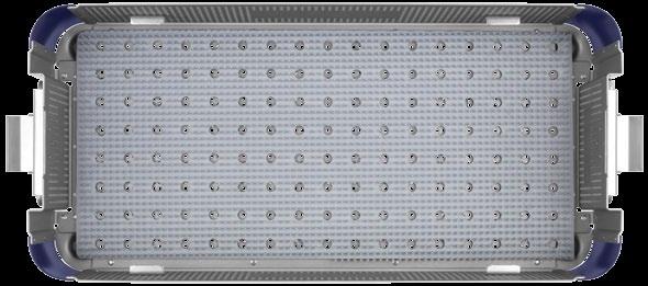
32 30 TransContinental implant set
33 TransContinental Implant Set Part No. Description Qty Part No. Description Qty TransContinental Spacer, Small, 0, 7mm TransContinental Spacer, Small, 0, 9mm TransContinental Spacer, Small, 0, mm TransContinental Spacer, Small, 0, 3mm TransContinental Spacer, Small, 0, 5mm TransContinental Spacer, Small, 0, 7mm TransContinental Spacer, Small, 6, 7mm TransContinental Spacer, Small, 6, 9mm 375. TransContinental Spacer, Small, 6, mm TransContinental Spacer, Small, 6, 3mm TransContinental Spacer, Small, 6, 5mm TransContinental Spacer, Small, 6, 7mm TransContinental Spacer, Medium, 0, 7mm TransContinental Spacer, Medium, 0, 9mm 375. TransContinental Spacer, Medium, 0, mm TransContinental Spacer, Medium, 0, 3mm TransContinental Spacer, Medium, 0, 5mm TransContinental Spacer, Medium, 0, 7mm TransContinental Spacer, Medium, 6, 7mm TransContinental Spacer, Medium, 6, 9mm TransContinental Spacer, Medium, 6, mm TransContinental Spacer, Medium, 6, 3mm TransContinental Spacer, Medium, 6, 5mm TransContinental Spacer, Medium, 6, 7mm TransContinental Spacer, Large, 0, 7mm TransContinental Spacer, Large, 0, 9mm TransContinental Spacer, Large, 0, mm TransContinental Spacer, Large, 0, 3mm TransContinental Spacer, Large, 6, 3mm TransContinental Spacer, Large, 6, 5mm TransContinental Spacer, Large, 6, 7mm TransContinental Spacer, X-Large, 0, 7mm TransContinental Spacer, X-Large, 0, 9mm TransContinental Spacer, X-Large, 0, mm TransContinental Spacer, X-Large, 0, 3mm TransContinental Spacer, X-Large, 0, 5mm TransContinental Spacer, X-Large, 0, 7mm TransContinental Spacer, X-Large, 6, 7mm TransContinental Spacer, X-Large, 6, 9mm TransContinental Spacer, X-Large, 6, mm TransContinental Spacer, X-Large, 6, 3mm TransContinental Spacer, X-Large, 6, 5mm TransContinental Spacer, X-Large, 6, 7mm TransContinental Spacer, X-Small, 0, 7mm TransContinental Spacer, X-Small, 0, 9mm TransContinental Spacer, X-Small, 0, mm TransContinental Spacer, X-Small, 0, 3mm TransContinental Spacer, X-Small, 0, 5mm TransContinental Spacer, X-Small, 0, 7mm TransContinental Spacer, X-Small, 6, 7mm TransContinental Spacer, X-Small, 6, 9mm TransContinental Spacer, X-Small, 6, mm TransContinental Spacer, X-Small, 6, 3mm TransContinental Spacer, X-Small, 6, 5mm TransContinental Spacer, X-Small, 6, 7mm TransContinental Graphic Case Implants TransContinental Spacer, Large, 0, 5mm TransContinental Spacer, Large, 0, 7mm TransContinental Spacer, Large, 6, 7mm TransContinental Spacer, Large, 6, 9mm TransContinental Spacer, Large, 6, mm LLIF Procedure 3


34 MARS 3V retractor set
35 MARS 3V Retractor Set Instruments Qty Retractor Blades Qty K-Wire Gripper retractor 3 Blade Frame 63.0 retractor Blade Frame mm Socket Driver hook and Latch Driver Flouro Modulator incision Locator Suction radiolucent Initial Dilator Holder cannula A cannula B cannula C cannula D Frame Handle Shim Tool, CC Docking Pin Tool Disc Shim Tool Docking Pin Sleeve 4 Retractor Blades Blade, Posterior, 40mm Blade, Posterior, 50mm Blade, Posterior, 60mm Blade, Posterior, 70mm Blade, Posterior, 80mm Blade, Posterior, 90mm Blade, Posterior, 00mm Blade, Posterior, 0mm Blade, Posterior, 0mm Blade, Posterior, 30mm Blade, Posterior, 40mm Blade, Posterior, 50mm Blade, Posterior, 60mm Blade, Posterior, 70mm Blade, CC, 40mm Blade, CC, 50mm Blade, CC, 60mm Blade, CC, 70mm Blade, CC, 80mm Blade, CC, 90mm Blade, CC, 00mm Blade, CC, 0mm Blade, CC, 0mm Blade, CC, 30mm Blade, CC, 40mm Blade, CC, 50mm Blade, CC, 60mm Blade, CC, 70mm Disposables S Bipolar Forceps, 0 Bayo,.0mm Tip S MARS 3V Disposable Kit S lengthening Shim S Widening Shim S Docking Pin, 0mm S Docking Pin, 0mm S Disc Shim, Aluminum S Disc Shim, Stainless Steel Items highlighted in gray are additionally available. LLIF Procedure 33


36 MARS instrument II set
37 MARS Instrument II Set Instruments Qty Fiber-Optic Cord adapter, ACMI adapter, Wolf adapter, Olympus adapter, Storz Port Lock, 9mm Port Lock, mm Port Lock, 6mm mm Cannula mm Cannula mm Cannula mm Cannula mm Cannula mm Cannula mm Cannula mm Port Mount mm Port Positioner mm Port Mount 63.4 mm Port Positioner mm Port Mount mm Port Positioner Table Clamp articulating Arm Assembly MARS Instrument II Graphic Case Items highlighted in gray are additionally available. LLIF Procedure 35


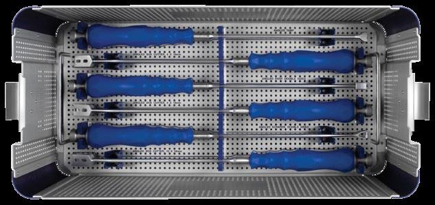
38 anterior disc prep I instrument set
39 Anterior Disc Prep I Instrument Set Instruments Qty Kerrison, mm 65.0 Kerrison, 4mm Kerrison, 6mm Bone Rongeur, Doube Acting, 8mm Bone Rongeur, Double Acting, mm Disc Rongeur, mm Disc Rongeur, mm, Up Biting Disc Rongeur, 4mm Disc Rongeur, 4mm, Up Biting Disc Rongeur, 6mm alif Trial Sizer, 9mm 65.6 alif Trial Sizer, mm alif Trial Sizer, 3mm alif Trial Sizer, 5mm alif Trial Sizer, 7mm alif Trial Sizer, 9mm 65.6 alif Trial Sizer, mm rotary Scraper, 9mm 65.7 rotary Scraper, mm rotary Scraper, 3mm rotary Scraper, 5mm rotary Scraper, 7mm Vein Retractor T-Handle with Impaction Cap, Long Parallel Distractor Knife Handle 65.8 long Penfield T-Handle with Impaction Cap 95.0 graphic Case LLIF Procedure 37


40 anterior disc prep II instrument set
41 Anterior Disc Prep II Instrument Set Instruments Qty Cobb Elevator, 8mm 65.0 cobb Elevator, Angled, 8mm cobb Elevator, 3mm cobb Elevator, Angled, 3mm ring Curette, 0mm ring Curette, 5mm Bone Curette, 3.5mm x 5.5mm, Straight Bone Curette, 3.5mm x 5.5mm, Up-Angled Bone Curette, 5.5mm x 8.5mm, Straight Bone Curette, 5.5mm x 8.5mm, Up-Angled Bone Curette, 7.5mm x.5mm, Straight Bone Curette, 7.5mm x.5mm, Up-Angled Dual Rasp angled Rasp Osteotome, 6mm x 0mm 95.0 graphic Case II Additionally Available Bone Curette, 9.5mm x 4.5mm, Straight Bone Curette, 9.5mm x 4.5mm, Up-Angled 65.4 Bone Curette,.5mm x 7.5mm, Straight 65.4 Bone Curette,.5mm x 7.5mm, Up-Angled Bone Curette, 3.5mm x 0.5mm, Straight Bone Curette, 3.5mm x 0.5mm, Up-Angled LLIF Procedure 39


42 lateral disc prep instrument set
43 Lateral Disc Prep Instrument Set Instruments Qty Slap Hammer Adaptor T-Handle with Impaction Cap quick Connect Guide large Cobb Elevator Small Cobb Elevator rasp Disc Rotary Cutter Box Cutter Thin Rasp, x0mm Cobb, 0mm, 7, Up-Angle Cobb, 0mm, 7, Up-Angle ring Curette, 0mm, Straight Ring Curette, 0mm, 7, Up-angle Tip cup Curette, 6.5x9.5mm, Straight Cup Curette, 6.5x9.5mm, 5, Up-angle Cup Curette, 6.5x9.5mm, 90, Down-angle Scaper, 7mm Scaper, 9mm Scaper, mm Scaper, 3mm Scaper, 5mm Scaper, 7mm TransContinental Disc Preparation Graphic Case Additionally Available S Bipolar Forceps Bayonetted, Straight 675.7S Bipolar Forceps Bayonetted, Angled LLIF Procedure 4

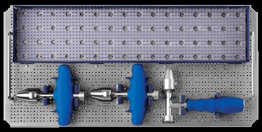


44 TransContinental INSERTION instruments SET
45 TransContinental Insertion Instruments Set Instruments Qty PATRIOT Continental Holder/Inserter long Throw Slide Hammer T-Handle with Impaction Cap TransContinental Trial, Parallel, 5mm TransContinental Trial, Parallel, 7mm TransContinental Trial, Parallel, 9mm TransContinental Trial, Parallel, mm TransContinental Trial, Parallel, 3mm TransContinental Trial, Parallel, 5mm TransContinental Trial, Parallel, 7mm TransContinental Trial, Lordotic, 5mm TransContinental Trial, Lordotic, 7mm TransContinental Trial, Lordotic, 9mm 675. TransContinental Trial, Lordotic, mm TransContinental Trial, Lordotic, 3mm TransContinental Trial, Lordotic, 5mm TransContinental Trial, Lordotic, 7mm insertion Sleeve Tamp l-handle TransContinental Graphic Case Insertion LLIF Procedure 43


46 lateral angled disc prep instrument set
47 Lateral Angled Disc Prep Instrument Set Instruments Qty T-Handle with Impaction Cap Cup, Curette, Angled, 6.5x9.5mm, Down Cup, Curette, Angled, 6.5x9.5mm, Up Cobb, Angled, 0mm, Down Cobb, Angled, 0mm, Up Cobb, Angled, 0mm, Down Cobb, Angled, 0mm, Up Double Sided Rasp, Angled Double Sided Scraper, Angled Rongeur, Angled, Left, 4mm Rongeur, Angled Right, 4mm Rongeur, Angled Left, 6mm Rongeur, Angled Right, 6mm Box Cutter, Angled, 6x8mm Box Cutter, Angled, 8x8mm Box Cutter, Angled, 0x8mm Tamp, Angled Angled Inserter Lateral Angled Disc Prep Graphic Case LLIF Procedure 45


48 TransContinental Angled Trials Set 46
49 TransContinental Angled Trials Set Part No. Description Qty mm Trial, Angled, Parallel, 5mm mm Trial, Angled, Parallel, 7mm mm Trial, Angled, Parallel, 9mm mm Trial, Angled, Parallel, mm mm Trial, Angled, Parallel, 3mm mm Trial, Angled, Parallel, 5mm mm Trial, Angled, Parallel, 7mm mm Trial, Angled, Parallel, 9mm mm Trial, Angled, Parallel, mm mm Trial, Angled, Parallel, 3mm mm Trial, Angled, Lordotic, 5mm mm Trial, Angled, Lordotic, 7mm mm Trial, Angled, Lordotic, 9mm mm Trial, Angled, Lordotic, mm mm Trial, Angled, Lordotic, 3mm mm Trial, Angled, 6 Lordotic, 5mm mm Trial, Angled, 6 Lordotic, 7mm mm Trial, Angled, 6 Lordotic, 9mm mm Trial, Angled, 6 Lordotic, mm mm Trial, Angled, 6 Lordotic, 3mm TransContinental Angled Trials Graphic Case Additionally Available mm Trial, Angled, Right Lordotic, 5mm mm Trial, Angled, Right Lordotic, 7mm mm Trial, Angled, Right Lordotic, 9mm mm Trial, Angled, Right Lordotic, mm mm Trial, Angled, Right Lordotic, 3mm mm Trial, Angled, Right Lordotic, 5mm mm Trial, Angled, Right Lordotic, 7mm mm Trial, Angled, Right Lordotic, 9mm mm Trial, Angled, Right Lordotic, mm mm Trial, Angled, Right Lordotic, 3mm LLIF Procedure 47
50 TransContinental 6mm Wide Implant Set Part No. Description Qty TransContinental Spacer, 0, 6x5mm, 7mm TransContinental Spacer, 0, 6x5mm, 9mm TransContinental Spacer, 0, 6x5mm, mm TransContinental Spacer, 0, 6x5mm, 3mm TransContinental Spacer, 0, 6x30mm, 7mm TransContinental Spacer, 0, 6x30mm, 9mm TransContinental Spacer, 0, 6x30mm, mm TransContinental Spacer, 0, 6x30mm, 3mm TransContinental Spacer, 0, 6x35mm, 7mm TransContinental Spacer, 0, 6x35mm, 9mm TransContinental Spacer, 0, 6x35mm, mm TransContinental Spacer, 0, 6x35mm, 3mm TransContinental Spacer, 0, 6x40mm, 7mm TransContinental Spacer, 0, 6x40mm, 9mm TransContinental Spacer, 0, 6x40mm, mm TransContinental Spacer, 0, 6x40mm, 3mm TransContinental Spacer, 0, 6x0mm, 7mm TransContinental Spacer, 0, 6x0mm, 9mm TransContinental Spacer, 0, 6x0mm, mm TransContinental Spacer, 0, 6x0mm, 3mm mm Trial 0 Lordotic, 5mm mm Trial 0 Lordotic, 7mm mm Trial 0 Lordotic, 9mm mm Trial 0 Lordotic, mm mm Trial 0 Lordotic, 3mm Insertion Sleeve Holder Inserter TransContinental Graphic Case - Implant, 6mm Wide 48
51 Bayonetted Disc Prep Instrument Set Instruments Qty Dual Convex Rasp, Bayonetted Bone Curette, Bayonetted, Small Bone Curette, Bayonetted, Up-Angled, Small Bone Curette, Bayonetted, 90, Small Bone Curette, Bayonetted, Large Bone Curette, Bayonetted, Up-Angled, Large Bone Curette, Bayonetted, 90, Large Ring Curette, Bayonetted, Up Angled Box Curette, Bayonetted, Up Angled, Wide Box Curette, Bayonetted, Up Angled, Narrow Nerve Retractor Penfield, Bayonetted, Push Penfield, Bayonetted, Pull Thin Rasp, Bayonetted, Straight Thin Rasp, Bayonetted, Angled Rake, Bayonetted Nerve Hook, Bayonetted Kerrison, Bayonetted, 3mm Kerrison, Bayonetted, 5mm Disc Rongeur, Bayonetted, mm, Straight Disc Rongeur, Bayonetted, mm, Up Disc Rongeur, Bayo, 4mm, Straight Disc Rongeur, Bayonetted, 4mm, Up Disc Rongeur, Bayonetted, 6mm, Straight Disc Rongeur, Bayonetted, 6mm, Up Bayonetted Lateral Instruments Graphic Case LLIF Procedure 49
52 TransContinental mm Implant Set Part No. Description Qty Part No. Description Qty TransContinental Spacer, mm Wide, Small, 0, 7mm TransContinental Spacer, mm Wide, Medium, 6, 7mm TransContinental Spacer, mm Wide, Small, 0, 9mm TransContinental Spacer, mm Wide, Large, 0, 7mm TransContinental Spacer, mm Wide, Small, 0, mm TransContinental Spacer, mm Wide, Large, 0, 9mm TransContinental Spacer, mm Wide, Small, 0, 3mm TransContinental Spacer, mm Wide, Large, 0, mm TransContinental Spacer, mm Wide, Small, 0, 5mm TransContinental Spacer, mm Wide, Large, 0, 3mm TransContinental Spacer, mm Wide, Small, 0, 7mm TransContinental Spacer, mm Wide, Large, 0, 5mm TransContinental Spacer, mm Wide, Small, 6, 7mm TransContinental Spacer, mm Wide, Large, 0, 7mm TransContinental Spacer, mm Wide, Small, 6, 9mm TransContinental Spacer, mm Wide, Large, 6, 7mm TransContinental Spacer, mm Wide, Small, 6, mm TransContinental Spacer, mm Wide, Large, 6, 9mm TransContinental Spacer, mm Wide, Small, 6, 3mm TransContinental Spacer, mm Wide, Large, 6, mm TransContinental Spacer, mm Wide, Small, 6, 5mm TransContinental Spacer, mm Wide, Large, 6, 3mm TransContinental Spacer, mm Wide, Small, 6, 7mm TransContinental Spacer, mm Wide, Large, 6, 5mm TransContinental Spacer, mm Wide, Medium, 0, 7mm TransContinental Spacer, mm Wide, Large, 6, 7mm TransContinental Spacer, mm Wide, Medium, 0, 9mm TransContinental Spacer, mm Wide, X-Large, 0, 7mm TransContinental Spacer, mm Wide, Medium, 0, mm TransContinental Spacer, mm Wide, X-Large, 0, 9mm TransContinental Spacer, mm Wide, Medium, 0, 3mm TransContinental Spacer, mm Wide, X-Large, 0, mm TransContinental Spacer, mm Wide, Medium, 0, 5mm TransContinental Spacer, mm Wide, X-Large, 0, 3mm TransContinental Spacer, mm Wide, Medium, deg, 7mm TransContinental Spacer, mm Wide, X-Large, 0, 5mm TransContinental Spacer, mm Wide, Medium, 6, 7mm TransContinental Spacer, mm Wide, X-Large, 0, 7mm TransContinental Spacer, mm Wide, Medium, 6, 9mm TransContinental Spacer, mm Wide, X-Large, 6, 7mm TransContinental Spacer, mm Wide, Medium, 6, mm TransContinental Spacer, mm Wide, X-Large, 6, 9mm TransContinental Spacer, mm Wide, Medium, 6, 3mm TransContinental Spacer, mm Wide, X-Large, 6, mm TransContinental Spacer, mm Wide, Medium, 6, 5mm TransContinental Spacer, mm Wide, X-Large, 6, 3mm 50
53 TransContinental mm Implant Set (cont'd) Part No. Description Qty Part No. Description Qty TransContinental Spacer, mm Wide, X-Large, 6, 5mm TransContinental Spacer, mm Wide, X-Large, 6, 7mm TransContinental Spacer, mm Wide, X-Small, 0, 7mm TransContinental Spacer, mm Wide, X-Small, 0, 9mm TransContinental Spacer, mm Wide, X-Small, 0, mm TransContinental Spacer, mm Wide, X-Small, 0, 3mm TransContinental Spacer, mm Wide, X-Small, 0, 5mm TransContinental Spacer, mm Wide, X-Small, 6, 7mm TransContinental Spacer, mm Wide, X-Small, 6, 9mm TransContinental Spacer, mm Wide, X-Small, 6, mm TransContinental Spacer, mm Wide, X-Small, 6, 3mm TransContinental Spacer, mm Wide, X-Small, 6, 5mm TransContinental mm Trial, Parallel, 5mm TransContinental mm Trial, Parallel, 7mm TransContinental mm Trial, Parallel, 9mm TransContinental mm Trial, Parallel, mm TransContinental mm Trial, Parallel, 3mm TransContinental mm Trial, Parallel, 5mm TransContinental mm Trial, Parallel, 7mm TransContinental mm Trial, 6 Lordotic, 5mm TransContinental mm Trial, 6 Lordotic, 7mm TransContinental mm Trial, 6, Lordotic, 9mm TransContinental mm Trial, 6, Lordotic, mm TransContinental mm Trial, 6, Lordotic, 3mm TransContinental mm Trial, 6, Lordotic, 5mm TransContinental mm Trial, 6, Lordotic, 7mm Insertion Sleeve, mm TransContinental mm Wide Implant Graphic Case Additionally Available TransContinental Spacer, mm Wide, X-Small, 0, 7mm TransContinental Spacer, mm Wide, X-Small, 6, 7mm LLIF Procedure 5
54 TransContinental 0 Lordotic Implant Set Part No. Description Qty Part No. Description Qty TransContinental Spacer, 8mm Wide, Small, 0, 7mm TransContinental Spacer, 8mm Wide, Small, 0, 9mm TransContinental Spacer, 8mm Wide, Small, 0, mm TransContinental Spacer, 8mm Wide, Small, 0, 3mm TransContinental Spacer, 8mm Wide, Small, 0, 5mm TransContinental Spacer, 8mm Wide, Small, 0, 7mm TransContinental Spacer, mm Wide, Small, 0, 7mm TransContinental Spacer, mm Wide, Small, 0, 9mm TransContinental Spacer, mm Wide, Small, 0, mm TransContinental Spacer, mm Wide, Small, 0, 3mm TransContinental Spacer, mm Wide, Small, 0, 5mm TransContinental Spacer, mm Wide, Small, 0, 7mm TransContinental Spacer, 8mm Wide, Medium, 0, 7mm TransContinental Spacer, 8mm Wide, Medium, 0, 9mm TransContinental Spacer, 8mm Wide, Medium, 0, mm TransContinental Spacer, 8mm Wide, Medium, 0, 3mm TransContinental Spacer, 8mm Wide, Medium, 0, 5mm TransContinental Spacer, 8mm Wide, Medium, 0, 7mm TransContinental Spacer, mm Wide, Medium, 0, 7mm TransContinental Spacer, mm Wide, Medium, 0, 9mm TransContinental Spacer, mm Wide, Medium, 0, mm TransContinental Spacer, mm Wide, Medium, 0, 3mm TransContinental Spacer, mm Wide, Medium, 0, 5mm TransContinental Spacer, mm Wide, Medium, 0, 7mm TransContinental Spacer, 8mm Wide, Large, 0, 7mm TransContinental Spacer, 8mm Wide, Large, 0, 9mm TransContinental Spacer, 8mm Wide, Large, 0, mm TransContinental Spacer, 8mm Wide, Large, 0, 3mm TransContinental Spacer, 8mm Wide, Large, 0, 5mm TransContinental Spacer, 8mm Wide, Large, 0, 7mm TransContinental Spacer, mm Wide, Large, 0, 7mm TransContinental Spacer, mm Wide, Large, 0, 9mm TransContinental Spacer, mm Wide, Large, 0, mm TransContinental Spacer, mm Wide, Large, 0, 3mm TransContinental Spacer, mm Wide, Large, 0, 5mm TransContinental Spacer, mm Wide, Large, 0, 7mm TransContinental Spacer, 8mm Wide, X-Large, 0, 7mm TransContinental Spacer, 8mm Wide, X-Large, 0, 9mm TransContinental Spacer, 8mm Wide, X-Large, 0, mm TransContinental Spacer, 8mm Wide, X-Large, 0, 3mm TransContinental Spacer, 8mm Wide, X-Large, 0, 5mm TransContinental Spacer, 8mm Wide, X-Large, 0, 7mm TransContinental Spacer, mm Wide, X-Large, 0, 7mm TransContinental Spacer, mm Wide, X-Large, 0, 9mm TransContinental Spacer, mm Wide, X-Large, 0, mm TransContinental Spacer, mm Wide, X-Large, 0, 3mm 5
55 TransContinental 0 Lordotic Implant Set (cont'd) Part No. Description Qty Part No. Description Qty TransContinental Spacer, mm Wide, X-Large, 0, 5mm TransContinental Spacer, mm Wide, X-Large, 0, 7mm TransContinental Spacer, 8mm Wide, X-Small, 0, 7mm TransContinental Spacer, 8mm Wide, X-Small, 0, 9mm TransContinental Spacer, 8mm Wide, X-Small, 0, mm TransContinental Spacer, 8mm Wide, X-Small, 0 3mm TransContinental Spacer, 8mm Wide, X-Small, 0, 5mm TransContinental Spacer, 8mm Wide, X-Small, 0, 7mm TransContinental Spacer, mm Wide, X-Small, 0, 7mm TransContinental Spacer, mm Wide, X-Small, 0, 9mm TransContinental Spacer, mm Wide, X-Small, 0, mm TransContinental Spacer, mm Wide, X-Small, 0, 3mm TransContinental Spacer, mm Wide, X-Small, 0, 5mm TransContinental Spacer, mm Wide, X-Small, 0, 7mm TransContinental 8mm Trial, 0 Lordotic, 5mm TransContinental 8mm Trial, 0 Lordotic, 7mm TransContinental 8mm Trial, 0 Lordotic, 9mm TransContinental 8mm Trial, 0 Lordotic, mm TransContinental 8mm Trial, 0 Lordotic, 3mm TransContinental 8mm Trial, 0 Lordotic, 5mm TransContinental 8mm Trial, 0 Lordotic, 7mm TransContinental mm Trial, 0 Lordotic, 5mm TransContinental mm Trial, 0 Lordotic, 7mm TransContinental mm Trial, 0 Lordotic, 9mm TransContinental mm Trial, 0 Lordotic, mm TransContinental mm Trial, 0 Lordotic, 3mm TransContinental mm Trial, 0 Lordotic, 5mm TransContinental mm Trial, 0 Lordotic, 7mm Insertion Sleeve Insertion Sleeve, mm TransContinental 0 Lordotic Implant Graphic Case LLIF Procedure 53
56 TransContinental Coronal Tapered Implant Set Part No. Description Qty Part No. Description Qty TransContinental Coronal Spacer, 0, 8x30mm, 9mm TransContinental Coronal Spacer, 0, 8x40mm, 7mm TransContinental Coronal Spacer, 0, 8x30mm, mm TransContinental Coronal Spacer, 0, 8x40mm, 9mm TransContinental Coronal Spacer, 0, 8x30mm, 3mm TransContinental Coronal Spacer, 0, 8x40mm, mm TransContinental Coronal Spacer, 0, 8x30mm, 5mm TransContinental Coronal Spacer, 0, 8x40mm, 3mm TransContinental Coronal Spacer, 0, 8x30mm, 7mm TransContinental Coronal Spacer, 0, 8x40mm, 5mm TransContinental Coronal Spacer, 0, 8x30mm, 9mm TransContinental Coronal Spacer, 0, 8x40mm, 7mm TransContinental Coronal Spacer, 0, 8x30mm, mm TransContinental Coronal Spacer, 0, 8x45mm, 9mm TransContinental Coronal Spacer, 0, 8x30mm, 3mm TransContinental Coronal Spacer, 0, 8x45mm, mm TransContinental Coronal Spacer, 0, 8x30mm, 5mm TransContinental Coronal Spacer, 0, 8x45mm, 3mm TransContinental Coronal Spacer, 0, 8x30mm, 7mm TransContinental Coronal Spacer, 0, 8x45mm, 5mm TransContinental Coronal Spacer, 0, 8x35mm, 9mm TransContinental Coronal Spacer, 0, 8x45mm, 7mm TransContinental Coronal Spacer, 0, 8x35mm, mm TransContinental Coronal Spacer, 0, 8x50mm, 9mm TransContinental Coronal Spacer, 0, 8x35mm, 3mm TransContinental Coronal Spacer, 0, 8x50mm, mm TransContinental Coronal Spacer, 0, 8x35mm, 5mm TransContinental Coronal Spacer, 0, 8x50mm, 3mm TransContinental Coronal Spacer, 0, 8x35mm, 7mm TransContinental Coronal Spacer, 0, 8x50mm, 5mm TransContinental Coronal Spacer, 0, 8x35mm, 9mm TransContinental Coronal Spacer, 0, 8x50mm, 7mm TransContinental Coronal Spacer, 0, 8x35mm, mm TransContinental Coronal Spacer, 0, 8x45mm, 9mm TransContinental Coronal Spacer, 0, 8x35mm, 3mm TransContinental Coronal Spacer, 0, 8x45mm, mm TransContinental Coronal Spacer, 0, 8x35mm, 5mm TransContinental Coronal Spacer, 0, 8x45mm, 3mm TransContinental Coronal Spacer, 0, 8x35mm, 7mm TransContinental Coronal Spacer, 0, 8x45mm, 5mm TransContinental Coronal Spacer, 0, 8x40mm, 9mm TransContinental Coronal Spacer, 0, 8x45mm, 7mm TransContinental Coronal Spacer, 0, 8x40mm, mm TransContinental Coronal Spacer, 0, 8x50mm, 9mm TransContinental Coronal Spacer, 0, 8x40mm, 3mm TransContinental Coronal Spacer, 0, 8x50mm, mm TransContinental Coronal Spacer, 0, 8x40mm, 5mm TransContinental Coronal Spacer, 0, 8x50mm, 3mm 54
57 TransContinental Coronal Tapered Implant Set (cont'd) Part No. Description Qty Part No. Description Qty TransContinental Coronal Spacer, 0, 8x50mm, 5mm TransContinental Coronal Spacer, 0, 8x50mm, 7mm TransContinental Coronal Spacer, 0, 8x55mm, 9mm TransContinental Coronal Spacer, 0, 8x55mm, mm TransContinental Coronal Spacer, 0, 8x55mm, 3mm TransContinental Coronal Spacer, 0, 8x55mm, 5mm TransContinental Coronal Spacer, 0, 8x55mm, 7mm TransContinental Coronal Spacer, 0, 8x60mm, 9mm TransContinental Coronal Spacer, 0, 8x60mm, mm TransContinental Coronal Spacer, 0, 8x60mm, 3mm TransContinental Coronal Spacer, 0, 8x60mm, 5mm TransContinental Coronal Spacer, 0, 8x60mm, 7mm TransContinental Coronal Spacer, 0, 8x55mm, 9mm TransContinental Coronal Spacer, 0, 8x55mm, mm TransContinental Coronal Spacer, 0, 8x55mm, 3mm TransContinental Coronal Spacer, 0, 8x55mm, 5mm TransContinental Coronal Spacer, 0, 8x55mm, 7mm TransContinental Coronal Spacer, 0, 8x60mm, 9mm TransContinental Coronal Spacer, 0, 8x60mm, mm TransContinental Coronal Spacer, 0, 8x60mm, 3mm TransContinental Coronal Spacer, 0, 8x60mm, 5mm TransContinental Coronal Spacer, 0, 8x60mm, 7mm Trial Leading 4 Coronal x 0 Lordotic, 7mm Trial Leading 4 Coronal x 0 Lordotic, 9mm Trial Leading 4 Coronal x 0 Lordotic, mm Trial Leading 4 Coronal x 0 Lordotic, 3mm Trial Leading 4 Coronal x 0 Lordotic, 5mm Trial Leading 4 Coronal x 0 Lordotic, 7mm Trial Trailing 4 Coronal x 0 Lodotic, 7mm Trial Trailing 4 Coronal x 0 Lodotic, 9mm Trial Trailing 4 Coronal x 0 Lodotic, mm Trial Trailing 4 Coronal x 0 Lodotic, 3mm Trial Trailing - 4 Coronal x 0 Lodotic, 5mm Trial Trailing - 4 Coronal x 0 Lodotic, 7mm Trial Leading 4 Coronal x 0 Lordotic, 7mm Trial Leading 4 Coronal x 0 Lordotic, 9mm Trial Leading 4 Coronal x 0 Lordotic, mm Trial Leading 4 Coronal x 0 Lordotic, 3mm Trial Leading 4 Coronal x 0 Lordotic, 5mm Trial Leading 4 Coronal x 0 Lordotic, 7mm Trial Trailing 4 Coronal x 0 Lordotic, 7mm Trial Trailing 4 Coronal x 0 Lordotic, 9mm Trial Trailing 4 Coronal x 0 Lordotic, mm Trial Trailing 4 Coronal x 0 Lordotic, 3mm Trial Trailing 4 Coronal x 0 Lordotic, 5mm Trial Trailing 4 Coronal x 0 Lordotic, 7mm Holder Inserter Coronal Insertion Sleeve, 8mm TransContinental Coronal Tapered Implant Graphic Case LLIF Procedure 55
58 IMPORTANT INFORMATION ON MARS (Minimal Access Retractor System) DESCRIPTION MARS (Minimal Access Retractor System) is a comprehensive retractor, ports and instrument system that provides efficient access to posterior lumbar spine. MARS and MARS 3V consists of a retractor frame, blades, disposable ports, silicone sleeves, light cables and associated manual surgical instruments. The blades and ports are available in several designs to accommodate individual patient anatomy. The MARS and MARS 3V instruments are made from aluminum and stainless steel as specified in ASTM B-0 and F The ports are made from radiolucent polymer (PEEK) as specified in ASTM F06. CLEANING Cleaning instructions by hand, when properly carried out, causes less damage than mechanical cleaning. When cleaning instruments by hand, the following should be observed:. Clear any corners or recesses of all debris. (Note: extra care should be taken to clean out any cannulated areas by using an appropriate cleaning stylet and rinsing immediately.). Remove all traces of blood and other such residues immediately. Do not allow these to dry. 3. The instruments should be submerged (if applicable) and cleaned with a commercially available manual cleaner (i.e. Instraclean from Calgon or Medline High Suds Detergent) prepared according to the manufacturer s recommendation. 4. A soft nylon bristled brush is then used to manually clean the devices while immersed in the cleaning solution. Never use steel brushes or abrasive pads, as these rupture the passive layer of the instrument surface which can lead to corrosion. 5. The instruments should be thoroughly rinsed after cleaning. Distilled water should be used. 6. Dry instruments immediately after cleaning. Implants: These devices are supplied NONSTERILE. Sterilization is recommended as follows: Method Cycle Type Temperature Exposure Time Steam Steam Gravity Displacement (Wrapped) Pre-vacuum (Wrapped) 3 C (70 F) 3 C (70 F) Drying Time 5 Minutes 45 Minutes 5 Minutes 30 Minutes Cycles should be performed on tray with devices opened for maximum steam penetration. These parameters are validated to sterilize only these instruments. If other products are added to the sterilizer, the recommended parameters are not valid and new cycle parameters must be established by the user. The autoclave must be properly installed, maintained, and calibrated. Ongoing testing must be performed to confirm inactivation of all forms of viable microorganisms. The following information is provided by LumitexMD, Inc. for MARS Light cable distributed by Globus Medical, Inc. CAUTION: Federal (USA) law restricts this device to sale by or on the order of a physician. INFORMATION FOR USE FOR THE MARS LIGHT CABLE DESCRIPTION The MARS Light Cable is a sterile, single use, latex free, plastic fiber optic device intended to bring cool area lighting into deep surgical sites. The MARS Light Cable is intended for use with a 300 watt xenon illuminator, using a 4mm fiber optic cable with a female ACMI connector. For best results use a Globus cable by LumitexMD. INDICATIONS FOR USE The MARS Light Cable is intended for the illumination of surgical procedures, particularly where deep cavities or adjacent tissues limit outside light in the surgical field. It is designed for use in less invasive spinal surgery. CONTRAINDICATIONS The MARS Light Cable presents no contraindication. However, the user should be familiar with the use of light sources and cables and should take precautions accordingly. WARNINGS The MARS Light Cable is designed for use with 300 watt xenon illuminators, using a 4mm fiber optic cable. Do not use light sources rated higher than 300 watts, or cables with fiber optic bundles of more than 4mm diameter. Use of higher watt sources or larger diameter cables could result in overheating; causing product failure and patient injury. Should the MARS Light Cable become cut, collect fluid inside, appear broken or damaged in any manner, it should be replaced to minimize risk to the patient. Do not operate the light source and cable without the MARS Light Cable attached. Without the MARS Light Cable, the output from the fiberoptic cable is extremely bright, hot and may cause burns, ignite drapes/gowns, or temporarily blind vision. PRECAUTIONS Light sources vary widely in emission of visible and infrared energy. As a precautionary measure, we recommend occasionally monitoring connector temperature during first time use with a new light source or lamp; thereafter if needed. As is common with fiber optic equipment, metal portion of connector can become hot to the touch. Use plastic grip as handle. Do not place the metal ring portion of connector directly on the patient s skin. Because light energy can be absorbed as heat, the entire lit portion (distal end) of the MARS Light Cable should not be continuously embedded (i.e. lit surface should not be completely buried) in tissue and held fixed for more than a few minutes at one time. Each MARS Light Cable package contains one MARS Light Cable assembly with an integrated adhesive strip and two double-sided adhesive strips. Each adhesive strip includes two paper release liners. Prior to closing the surgical site, all components must be accounted for. After use, this product may be a potential biohazard. Handle and dispose of in accordance with accepted medical practice and applicable local, state and federal laws and regulations. 56
59 IMPORTANT INFORMATION ON MARS (Minimal Access Retractor System) DIRECTIONS FOR USE Attach the MARS Light Cable to the Globus Medical MARS retractor using the integrated stainless steel clip located on the back of each MARS Light Cable. The MARS Light Cable connects to a light source used for head lamps or endoscopes. A fiber optic cable attaches the light source and MARS Light Cable. Make sure the MARS Light Cable connector is securely attached to the cable. The cable should be in good repair with clean optics. Dirty optics or cables in need of repair can cause excessive heat at the connectors. Turning down overhead lighting may improve visualization within the surgical site. Body fluids or debris collecting on the surface of the MARS Light Cable may be irrigated or wiped away. Sterile unless package is opened or damaged. Do not use if package is opened or damaged. LIMITED WARRANTY LumitexMD warrants the material conformity of the MARS Light Cable to specifications in the product labeling until the earlier of months from shipment to customer or the expiration date of the product, and will repair or replace at LumitexMD option and expense any LumitexMD product that does not meet specifications in all material respects. LUMITEXMD LIABILITY TO CUSTOMER, USER, OR PATIENT IS EXPRESSLY LIMITED TO REPAIR OR REPLACEMENT. LumitexMD expressly disclaims all other warranties, express or implied, including, without limitation, merchantability or fitness for a particular purpose. Please direct any inquires to Globus Medical. Distributed by: Manufactured by: Globus Medical, Inc. LumitexMD, Inc. Valley Forge Business Center Dow Circle General Armisted Avenue Strongsville, OH 4436 USA Audubon, PA 9403 Tel: Tel: Fax: medical@lumitex.com Authorized EC Representative: Medical Device Safety Service GmbH Schiffgraben 4 D-3075 Hannover, Germany Plastic grip Metal ring Connector REV E LLIF Procedure 57
60 IMPORTANT INFORMATION on the patriot lumbar spacer system DESCRIPTION The PATRIOT Spacers (Constitution PLIF, Signature TLIF, Continental ALIF, TransContinental and TransContinental M Spacers) are lumbar interbody fusion devices used to provide structural stability in skeletally mature individuals following discectomy. Each of the PATRIOT spacers provides a different shape to accommodate various surgical approaches to the lumbar spine. The Constitution PLIF Spacer is inserted using a posterior approach. The SIGNATURE TLIF Spacer is inserted using a transforaminal approach. The CONTINENTAL ALIF Spacer is inserted using an anterior approach. The TransContinental and TransContinental M Spacer are inserted using an anterior or lateral approach. The devices are available in various heights and geometric options to fit the anatomical needs of a wide variety of patients. These spacers are to be filled with autogenous bone graft material. Protrusions on the superior and inferior surfaces of each device grip the endplates of the adjacent vertebrae to resist expulsion. PATRIOT Spacers are made from PEEK radiolucent polymer, with titanium alloy or tantalum markers, as specified in ASTM F06, F36, F95, and F560. The TransContinental M Spacer also includes an integrated titanium alloy nut, as specified in ASTM F36, F95. INDICATIONS PATRIOT Spacers (Constitution PLIF, Signature TLIF, Continental ALIF, TransContinental and TransContinental M Spacers) are interbody fusion devices intended for use in patients with degenerative disc disease (DDD) at one or two contiguous levels of the lumbosacral spine (L-S). DDD is defined as discogenic back pain with degeneration of the disc confirmed by history and radiographic studies. These patients should be skeletally mature and have had at least six (6) months of non-operative treatment. In addition, these patients may have up to Grade spondylolisthesis or retrolisthesis at the involved level(s). PATRIOT Spacers are to be filled with autogenous bone graft material. These devices are intended to be used with supplemental fixation. WARNINGS One of the potential risks identified with this system is death. Other potential risks which may require additional surgery, include: device component fracture, loss of fixation, non-union, fracture of the vertebrae, neurological injury, and vascular or visceral injury. Interbody fusion devices for the treatment of degenerative conditions are designed to withstand both full load bearing and the loads associated with long-term use which could result from the presence of non-union or delayed union. Certain degenerative diseases or underlying physiological conditions such as diabetes, rheumatoid arthritis, or osteoporosis may alter the healing process, thereby increasing the risk of implant breakage or spinal fracture. Patients with previous spinal surgery at the level(s) to be treated may have different clinical outcomes compared to those without previous surgery. Components of this system should not be used with components of any other system or manufacturer. The components of this system are manufactured from PEEK radiolucent polymer, titanium alloy, and tantalum. Mixing of stainless steel implant components with different materials is not recommended for metallurgical, mechanical and functional reasons. PRECAUTIONS The implantation of intervertebral fusion devices should be performed only by experienced spinal surgeons with specific training in the use of this system because this is a technically demanding procedure presenting a risk of serious injury to the patient. Preoperative planning and patient anatomy should be considered when selecting implant size. Surgical implants must never be reused. An explanted implant must never be reimplanted. Even though the device appears undamaged, it may have small defects and internal stress patterns which could lead to breakage. Adequately instruct the patient. Mental or physical impairment which compromises or prevents a patient s ability to comply with necessary limitations or precautions may place that patient at a particular risk during postoperative rehabilitation. The PATRIOT Spacers have not been evaluated for safety and compatibility in the MR environment. The PATRIOT Spacers have not been tested for heating or migration in the MR environment. For optimal implant performance, when using the PATRIOT Spacers, the physicians/surgeon should consider the levels of implantation, patient weight, patient activity level, other patient conditions, etc., which may impact on the performance of this system. CONTRAINDICATIONS Use of PATRIOT Spacer(s) is contraindicated in patients with the following conditions:. Active systemic infection, infection localized to the site of the proposed implantation, or when the patient has demonstrated allergy or foreign body sensitivity to any of the implant materials.. Prior fusion at the level(s) to be treated. 3. Severe osteoporosis, which may prevent adequate fixation 4. Conditions that may place excessive stresses on bone and implants, such as severe obesity or degenerative diseases, are relative contraindications. The decision whether to use these devices in such conditions must be made by the physician taking into account the risks versus the benefits to the patient. 5. Patients whose activity, mental capacity, mental illness, alcoholism, drug abuse, occupation, or lifestyle may interfere with their ability to follow postoperative restrictions and who may place undue stresses on the implant during bony healing and may be at a higher risk of implant failure. 6. Any condition not described in the indications for use. CONTACT INFORMATION Globus Medical may be contacted at -866-GLOBUS (456-87). A surgical technique manual may be obtained by contacting Globus Medical. STERILIZATION The PATRIOT Spacer implants and instruments have been validated to assure a Sterility Assurance Level (SAL) of 0-6. The use of an FDA cleared wrap is recommended, per the Association for the Advancement of Medical Instrumentation (AAMI) ST79, Comprehensive Guide to Steam Sterilization and Sterility Assurance in Health Care Facilities. Implants: These devices are supplied NONSTERILE. Sterilization is recommended as follows: Method Cycle Type Temperature Exposure Time Drying Time Steam Steam Gravity Displacement (Wrapped) Pre-vacuum (Wrapped) 3 C (70 F) 3 C (70 F) 0 minutes 5 minutes 4 minutes 5 minutes Instruments: These instruments are supplied NONSTERILE. Sterilization is recommended as follows: Method Cycle Type Temperature Exposure Time Drying Time Steam Steam Gravity Displacement (Wrapped) Pre-vacuum (Wrapped) 3 C (70 F) 3 C (70 F) 5 minutes 5 minutes 5 minutes 0 minutes These parameters are validated to sterilize only this device. If other products are added to the sterilizer, the recommended parameters are not valid and new cycle parameters must be established by the user. The autoclave must be properly installed, maintained, and calibrated. Ongoing testing must be performed to confirm inactivation of all forms of viable microorganisms. CAUTION: Federal (USA) Law Restricts this Device to Sale by or on the order of a Physician. 58 REV E
61 Notes LLIF Procedure 59
62 60 Notes
63 Notes LLIF Procedure 6
 Fax -866-GLOBUS3 (or -866-456-873) 0 Globus Medical. All rights reserved. Patents pending.")

64 Globus Medical Valley Forge Business Center 560 General Armistead Avenue Audubon, PA Customer Service: Phone -866-GLOBUS (or ) Fax -866-GLOBUS3 (or ) 0 Globus Medical. All rights reserved. Patents pending. Life moves us is a registered trademark of Globus Medical. MARS is a trademark of Globus Medical. CONTINENTAL, PATRIOT, REVERE, REVOLVE and TransContinental are registered trademarks of Globus Medical. Please refer to package insert for description, indications, contraindications, warnings, precautions and other important information. P: RMS UK Limited 8 Trinity Road, Nailsea, Somerset, BS48 4NU England GMTGD3.
Imola Lateral IBF System Surgical Technique
 Imola Lateral IBF System Surgical Technique IMOLA CIRCUIT TABLE OF CONTENTS Design Rationale Instructions for Use Surgical Technique 1. Table Mounting 2. Surgical Planning & Targeting 3. Access and Preparation
O PE RATIV E TE C HN IQ U E. ProView. Expandable Retractor System U.S. EDITION
 O PE RATIV E TE C HN IQ U E ProView M I N I M A L A C C E S S P O R TA L ( M A P ) S Y S T E M Expandable Retractor System U.S. EDITION Table of Contents 1 INTRODUCTION 2 OPERATIVE TECHNIQUE 9 PART NUMBERS
M.I.S. MAKE IT SMART IN ONE SYSTEM. Surgical Technique. Hip Knee Spine Navigation
 M.I.S. MAKE IT SMART IN ONE SYSTEM Surgical Technique Hip Knee Spine Navigation M.U.S.T. Mini Open Surgical Technique Hip Knee Spine Navigation 2 C O N T E N T S 1 INTRODUCTION 4 2 SURGICAL TECHNIQUE 5
LUMBAR POSTERIOR MINIMALLY INVASIVE SYSTEM. Surgical Technique
 LUMBAR POSTERIOR MINIMALLY INVASIVE SYSTEM Surgical Technique Joint Spine Sports Med M.U.S.T. Mini Open Surgical Technique Joint Spine Sports Med CAUTION Federal law (USA) restricts this device to sale
VTI INTERFUSE T SURGICAL TECHNIQUE FORWARD THINKING FOR THE BACK. 1/20
 VTI INTERFUSE T SURGICAL TECHNIQUE FORWARD THINKING FOR THE BACK. 1/20 CONTENTS InterFuse T Product Description Indications for Use X-Ray Marker Locations Product Specifications Instrument Set 3 4 5 STEP
Cervical Solutions. Optio-C Anterior Cervical Plate. with Allograft/Autograft. Surgical Technique Guide
 Cervical Solutions Optio-C Anterior Cervical Plate with Allograft/Autograft Surgical Technique Guide 2 Optio-C Anterior Cervical Plate with Allograft/Autograft Surgical Technique Guide The Optio-C System
SURGICAL TECHNIQUE MANUAL. InterFuse T
 1 CONTENTS InterFuse T Product Description 3 Indications for Use 3 X-Ray Marker Locations 4 Product Specifications 4 Instrument Set 5 Step 1 Preoperative Planning 8 Patient Positioning 8 Step 2 Disc Removal
VTI INTERFUSE S SURGICAL TECHNIQUE FORWARD THINKING FOR THE BACK.
 VTI INTERFUSE S SURGICAL TECHNIQUE FORWARD THINKING FOR THE BACK. CONTENTS InterFuse S Product Description Indications for Use X-Ray Marker Locations and Product Specifications Instrument Set 3 4 5-7 STEP
PILLAR AL. Anterior Lumbar Interbody Fusion (ALIF) and Partial Vertebral Body Replacement (pvbr) PEEK Spacer System OPERATIVE TECHNIQUE
 and Partial Vertebral Body Replacement (pvbr) PEEK Spacer System OPERATIVE TECHNIQUE") PILLAR AL PEEK Spacer System Anterior Lumbar Interbody Fusion (ALIF) and Partial Vertebral Body Replacement (pvbr) OPERATIVE TECHNIQUE Table of Contents 1 INTRODUCTION 2 PRE-OPERATIVE TECHNIQUE 3 OPERATIVE
PILLAR AL PEEK Spacer System Anterior Lumbar Interbody Fusion (ALIF) and Partial Vertebral Body Replacement (pvbr) OPERATIVE TECHNIQUE Table of Contents 1 INTRODUCTION 2 PRE-OPERATIVE TECHNIQUE 3 OPERATIVE
EXACTECH SPINE. Operative Technique. Cervical Spacer System. Surgeon focused. Patient driven. TM
 EXACTECH SPINE Operative Technique Cervical Spacer System Surgeon focused. Patient driven. TM ACAPELLA ONE Acapella One Cervical Spacer System is an anterior cervical discectomy and fusion device with
Cervical Spacer System surgical technique
 Blackhawk TM Cervical Spacer System surgical technique Blackhawk TM The BLACKHAWK Cervical Spacer System is designed to provide biomechanical stabilization as an adjunct to fusion. Spinal fixation should
BAK/C Cervical Anterior Interbody Fusion System
 Surgical Technique BAK/C Cervical Anterior Interbody Fusion System The Comfortable Choice for Cervical Fusion BAK/C Cervical Surgical Technique 1 The BAK/C Cervical Fusion System is an alternative to conventional
Solitaire Anterior Spinal System
 Surgical Technique Solitaire Anterior Spinal System Independent Stabilization for the Anterior Column Available in Titanium and Contents Introduction... Page 1 Design Features... Page 2 Instruments...
INSIGHT LATERAL ACCESS SYSTEM Minimal invasive access system for the thoracolumbar spine.
 INSIGHT LATERAL ACCESS SYSTEM Minimal invasive access system for the thoracolumbar spine. Instruments and implants approved by the AO Foundation. This publication is not intended for distribution in the
Surgical Technique Manual
 InterFuse S Interbody Fusion System Surgical Technique Manual VERTEBRAL TECHNOLOGIES MS 4043-02 Rev. O Product Overview Introduction The VTI InterFuse S implant is an interbody fusion device that combines
Valencia Pedicle Screw Surgical Technique
 Valencia Pedicle Screw Surgical Technique VALENCIA CIRCUIT TABLE OF CONTENTS Design Rationale Indications for Use Surgical Technique 1. Pedicle Preparation 2. Screw Insertion 3. Rod Placement 4. Locking
TABLE OF CONTENTS. ShurFit Anterior Cervical Interbody Fusion (ACIF) System Overview 2. Implant Specifications 3. Instrument Features 4
 System Overview 2. Implant Specifications 3. Instrument Features 4") Surgical Technique TABLE OF CONTENTS ShurFit Anterior Cervical Interbody Fusion (ACIF) System Overview 2 Product Highlights 2 Indications 2 Implant Specifications 3 Instrument Features 4 Surgical Technique
Surgical Technique TABLE OF CONTENTS ShurFit Anterior Cervical Interbody Fusion (ACIF) System Overview 2 Product Highlights 2 Indications 2 Implant Specifications 3 Instrument Features 4 Surgical Technique
Surgical Technique. TraXis. Precision. Transforaminal Lumbar Interbody Fusion Spacer. The Art & Science of Spine Surgery
 Surgical Technique Precision TraXis Transforaminal Lumbar Interbody Fusion Spacer The Art & Science of Spine Surgery Table of Contents Introduction 3 Indications 4 Key Instruments 5 Surgical Technique
Posterior Lumbar Interbody Fusion System
 Px Posterior Lumbar Interbody Fusion System Px PEEK INTERBODY FUSION SYSTEM INDICATIONS FOR USE The Innovasis Px PEEK IBF System is an intervertebral body fusion device for use in patients with degenerative
C-THRU Anterior Spinal System
 C-THRU Anterior Spinal System Surgical Technique Manufactured From Contents Introduction... Page 1 Design Features... Page 2 Instruments... Page 3 Surgical Technique... Page 4 Product Information... Page
OPERATIVE TECHNIQUE COVER IMAGE OPTIONAL (DETAIL) IMAGE SKYHAWK. lateral interbody fusion system lateral plate system
 IMAGE SKYHAWK. lateral interbody fusion system lateral plate system") OPERATIVE TECHNIQUE COVER IMAGE OPTIONAL (DETAIL) IMAGE SKYHAWK lateral interbody fusion system lateral plate system TABLE OF CONTENTS Introduction 1 Pre-Operative Technique 2 Operative Technique 3 Part
OPERATIVE TECHNIQUE COVER IMAGE OPTIONAL (DETAIL) IMAGE SKYHAWK lateral interbody fusion system lateral plate system TABLE OF CONTENTS Introduction 1 Pre-Operative Technique 2 Operative Technique 3 Part
XRL A modular expandable radiolucent vertebral body replacement system
 XRL A modular expandable radiolucent vertebral body replacement system This publication is not intended for distribution in the USA. SURGICAL TECHNIQUE Table of Contents Introduction XRL 2 AO Spine Principles
TECHNICAL BROCHURE. Capture Facet Fixation System
 TECHNICAL BROCHURE Capture Facet Fixation System Table of Contents Product Overview...2 Instruments...4 Capture Facet Screw Surgical Technique Patient Preparation and Positioning...6 Guide Pin Placement...7
Thoracolumbar Solutions. Timberline. Lateral Fusion System. Surgical Technique Guide
 Thoracolumbar Solutions Timberline Lateral Fusion System Surgical Technique Guide 2 Timberline Lateral Fusion System Surgical Technique A complete and comprehensive minimally invasive lateral system consisting
HawkeyeTM Peek. surgical technique
 HawkeyeTM Peek surgical technique Introduction The ChoiceSpine HAWKEYE Vertebral Body Replacement (VBR) System is intended for use in the thoracolumbar spine (T1 - L5) to replace a collapsed, damaged,
Surgical technique. SynCage-C short
 Surgical technique SynCage-C short Table of contents Implants 2 Indications/contra-indications 3 Surgical technique 4 Image intensifier control Warning This description is not sufficient for immediate
SynCage-C short. Surgical Technique. This publication is not intended for distribution in the USA.
 SynCage-C short Surgical Technique This publication is not intended for distribution in the USA. Instruments and implants approved by the AO Foundation. Table of contents Implants 2 Indications/contra-indications
Trilogy Acetabular System
 Trilogy Acetabular System Surgical Technique Versatility in a proven design Trilogy Acetabular System 1 Trilogy Acetabular System Surgical Technique Table of Contents Acetabular Reaming 2 Component Sizing
3. PATIENT POSITIONING & FRACTURE REDUCTION 3 8. DISTAL GUIDED LOCKING FOR PROXIMAL NAIL PROXIMAL LOCKING FOR LONG NAIL 13
 Contents IMPLANT FEATURES 2 1. INDICATIONS 3 2. PRE-OPERATIVE PLANNING 3 3. PATIENT POSITIONING & FRACTURE REDUCTION 3 4. INCISION 4 5. ENTRY POINT 4-6 6. PROXIMAL NAIL INSERTION 6-7 7. PROXIMAL LOCKING
EXCELLA ll. Spinal System
 EXCELLA ll Spinal System Excella II Spinal System INDICATIONS FOR USE The Innovasis Excella II Spinal System is intended for use in the non-cervical area of the spine. WARNING: The safety and effectiveness
Technique Guide. Insight Retractor. Minimal invasive access system to the posterior thoracolumbar spine.
 Technique Guide Insight Retractor. Minimal invasive access system to the posterior thoracolumbar spine. Table of Contents Introduction Insight Retractor 2 AO Principles 4 Indications and Contraindications
Trilogy Acetabular System
 Trilogy Acetabular System Surgical Technique Versatility in a proven design Trilogy Acetabular System 1 Trilogy Acetabular System Surgical Technique Table of Contents Acetabular Reaming 2 Component Sizing
Zimmer Trabecular Metal Ankle Interpositional Spacer and Trabecular Metal Ankle Fusion Spacer
 Zimmer Trabecular Metal Ankle Interpositional Spacer and Trabecular Metal Ankle Fusion Spacer Surgical Technique 2 Zimmer Trabecular Metal Ankle Interpositional Spacer and Trabecular Metal Ankle Fusion
OPTIONAL/ADDITIONAL INSTRUMENTS
 20 Elevated 6320-36-22 20 Elevated Rim Liner, 36mm OD x 22mm ID 6320-80-22 20 Elevated Rim Liner, 80mm OD x 22mm ID 6320-42-26 20 Elevated Rim Liner, 42mm OD x 26mm ID 6320-80-26 20 Elevated Rim Liner,
Advantage ALIF. Keith Shevlin Managing Director
 Advantage ALIF Unit 10, 9-11 Myrtle Street, Crows Nest NSW 2065 Keith Shevlin Managing Director keithshevlin@precisionsurgical.com.au Advantage ALIF Introduction & Indications for Use 1 Surgical Technique
Royal Oak IBFD System Surgical Technique Posterior Lumbar Interbody Fusion (PLIF)
") Royal Oak IBFD System Surgical Technique Posterior Lumbar Interbody Fusion (PLIF) Preoperative Planning Preoperative planning is necessary for the correct selection of lumbar interbody fusion devices.
Royal Oak IBFD System Surgical Technique Posterior Lumbar Interbody Fusion (PLIF) Preoperative Planning Preoperative planning is necessary for the correct selection of lumbar interbody fusion devices.
100 Interpace Parkway Parsippany, NJ
 100 Interpace Parkway Parsippany, NJ 07054 www.biometspine.com 800-526-2579 All trademarks are the property of Biomet, Inc. or one of its subsidiaries, unless otherwise indicated. Rx Only. 2009 EBI, LLC.
Technique Guide. Oracle Spacer System. Instruments and implants for a direct lateral approach to the lumbar spine.
 Technique Guide Oracle Spacer System. Instruments and implants for a direct lateral approach to the lumbar spine. Table of Contents Introduction Oracle Spacer System 2 AO Principles 4 Indications 5 Surgical
Surgical Technique Guide
 Sacroiliac Joint Fusion System Surgical Technique Guide Moving Life Forward Table of Contents SiCure Implant Overview...2 SiCure System Information...3 X-ray Basics...4 Patient Positioning....5 Surgical
LCP Medial Distal Tibia Plate, without Tab. The Low Profile Anatomic Fixation System with Angular Stability and Optimal Screw Orientation.
 LCP Medial Distal Tibia Plate, without Tab. The Low Profile Anatomic Fixation System with Angular Stability and Optimal Screw Orientation. Technique Guide LCP Small Fragment System Table of Contents Introduction
Fusion Device. Surgical Technique. Cervical Interbody Fusion with Trabecular Metal Technology
 TM-S Fusion Device Surgical Technique Cervical Interbody Fusion with Trabecular Metal Technology 2 TM-S Fusion Device Surgical Technique Disclaimer This surgical technique is not intended for use in the
System. Humeral Nail. Surgical Technique
 System Humeral Nail Surgical Technique Contents IMPLANT FEATURES 2 1. INDICATIONS 3 2. PRE-OPERATIVE PLANNING 3 3. PATIENT POSITIONING & FRACTURE REDUCTION 3 4. INCISION 4 5. ENTRY POINT 4-6 6. PROXIMAL
Threshold Pedicular Fixation System Surgical Technique
 Threshold Pedicular Fixation System Surgical Technique Table of Contents Patient Preparation and Positioning... 2 Determining Incision Location... 3 Assembling the Cannulated Awl... 4 Guide Wire Placement...
nva Anterior Lumbar Interbody Fusion System
 nva Anterior Lumbar Interbody Fusion System 1 IMPORTANT INFORMATION FOR PHYSICIANS, SURGEONS, AND/OR STAFF The nv a, nv p, and nv t are an intervertebral body fusion device used in the lumbar spine following
product overview Implant heights range from 8mm-20mm in 2mm increments, with two lordocic angle options of 6 and 12.
 ETHOS A-Spacer PEEK System Surgical Technique Guide Synchronizing Medical Innovation with Global Markets product overview The SyncMedical Ethos PEEK IBF System is an intervertebral body fusion device for
Technique Guide. 3.5 mm LCP Low Bend Medial Distal Tibia Plate Aiming Instruments. Part of the 3.5 mm LCP Percutaneous Instrument System.
 Technique Guide 3.5 mm LCP Low Bend Medial Distal Tibia Plate Aiming Instruments. Part of the 3.5 mm LCP Percutaneous Instrument System. Table of Contents Introduction 3.5 mm LCP Low Bend Medial Distal
Transforaminal Lumbar Interbody Fusion Cage (TLIF)
") Transforaminal Lumbar Interbody Fusion age (TLIF) 990100010 DOULE ENGINE MEDIL MTERIL O., LTD. No. 218 Houxiang Road, Haicang District, Xiamen 361022, P.R.hina Tel: +86 592 6087101 Fax: +86 592 6587078
Transforaminal Lumbar Interbody Fusion age (TLIF) 990100010 DOULE ENGINE MEDIL MTERIL O., LTD. No. 218 Houxiang Road, Haicang District, Xiamen 361022, P.R.hina Tel: +86 592 6087101 Fax: +86 592 6587078
L-VARLOCK. Posterior Lumbar Cage with adjustable lordosis. S urgical T echnique
 L-VARLOCK Posterior Lumbar Cage with adjustable lordosis S urgical T echnique Introduction Designed and manufactured by KISCO International, L-VARLOCK cages are made of titanium alloy Ti 6AI 4V (standards
SYNFIX EVOLUTION SECURED SPACER SYSTEM
 SYNFIX EVOLUTION SECURED SPACER SYSTEM Instruments and implants for stand-alone anterior lumbar interbody fusion Instruments and implants approved by the AO Foundation. This publication is not intended
POSTERIOR SPINE TRUSS SYSTEM
 POSTERIOR SPINE TRUSS SYSTEM ORDERING & SHIPPING ALL FIELDS ARE REQUIRED ORDER FORM PLEASE PRINT LEGIBLY RECEIVING YOUR PSTS TRAYS & IMPLANTS All implant bins and trays have a warehouse number on them
nvp Posterior Lumbar Interbody Fusion System
 nvp Posterior Lumbar Interbody Fusion System 1 IMPORTANT INFORMATION FOR PHYSICIANS, SURGEONS, AND/OR STAFF The nv a, nv p, and nv t are an intervertebral body fusion device used in the lumbar spine following
Spinal Correction FRA Spacer System. For use with the Small Stature FRA Spacer and the FRA Spacer.
 Spinal Correction FRA Spacer System. For use with the Small Stature FRA Spacer and the FRA Spacer. Technique Guide Instruments and implants approved by the AO Foundation Table of Contents Introduction
TM TM Surgical Technique
 TM TM Surgical Technique TABLE OF CONTENTS Reli SP Spinous Plating System Overview Device Description Implant Features Indications Instruments Access Instruments Preparation Instruments Insertion Instruments
Technique Guide. 3.5 mm LCP Low Bend Medial Distal Tibia Plates. Part of the Synthes locking compression plate (LCP) system.
 system.") Technique Guide 3.5 mm LCP Low Bend Medial Distal Tibia Plates. Part of the Synthes locking compression plate (LCP) system. Table of Contents Introduction 3.5 mm LCP Low Bend Medial Distal Tibia Plates
Technique Guide 3.5 mm LCP Low Bend Medial Distal Tibia Plates. Part of the Synthes locking compression plate (LCP) system. Table of Contents Introduction 3.5 mm LCP Low Bend Medial Distal Tibia Plates
Veyron -C Anterior Cervical System Surgical Technique
 Veyron -C Anterior Cervical System Surgical Technique 2 Veyron-C Anterior Cervical System Surgical Technique Veyron-C Anterior Cervical System Surgical Technique Description, Indications & Contraindications...3
VECTRA-T SURGICAL TECHNIQUE. The Translational Anterior Cervical Palate System. This publication is not intended for distribution in the USA.
 VECTRA-T The Translational Anterior Cervical Palate System This publication is not intended for distribution in the USA. SURGICAL TECHNIQUE Image intensifier control This description alone does not provide
Surgical Technique. CONQUEST FN Femoral Neck Fracture System
 Surgical Technique CONQUEST FN Femoral Neck Fracture System Table of Contents Introduction... 3 Indications... 3 Product Overview... 4 Surgical Technique... 5 Patient Positioning... 5 Reduce the Fracture...
Thunderbolt. surgical technique. MIS Pedicle Screw System. Where Nimble and Secure Intersect
 Thunderbolt TM MIS Pedicle Screw System Where Nimble and Secure Intersect surgical technique i www.choicespine.com System Features Dovetail set screw: Minimizes head splay and cross-threading Secure connection
SynCage. Surgical Technique. This publication is not intended for distribution in the USA. Instruments and implants approved by the AO Foundation.
 SynCage Surgical Technique This publication is not intended for distribution in the USA. Instruments and implants approved by the AO Foundation. Image intensifier control Warning This description alone
EFSPINE CERVICAL COMBINED SET DISC PROTHESIS ORGANIZER BOX
 EFSPINE CERVICAL COMBINED SET INSTRUMENTS CERVICAL CAGE & DISC PROTHESIS ORGANIZER BOX Cervical Thoracic Thoraco - Lumbar Sacral EFSPINE CERVICAL COMBINED SET CERVICAL IMPLANTS INTRODUCTION Cervical Disc
Surgical Technique SUSTAIN -O. Radiolucent Spacer
 Surgical Technique SUSTAIN -O Radiolucent Spacer At Globus, we move with a sense of urgency to deliver innovations that improve the quality of life for patients with spinal disorders. We are inspired by
Correction System. Surgical Technique
 Nextra Hammertoe Correction System Surgical Technique Maximized Bone Purchase* Stable and Secure Phalanx Optimized Screw Design Adjustable Bone-to-Bone Apposition Progressive Ratchet Tightening Mechanism
Ballista Percutaneous Screw Placement System
 Surgical Technique Ballista Percutaneous Screw Placement System A Minimally Invasive Approach for Posterior Spinal Surgery True percutaneous system Helical Flange locking mechanism Contents Introduction...
T-PAL. Transforaminal Posterior Atraumatic Lumbar Cage System.
 T-PAL. Transforaminal Posterior Atraumatic Lumbar Cage System. Technique Guide This publication is not intended for distribution in the USA. Instruments and implants approved by the AO Foundation. Image
Cervical Solutions. Optio-C Anterior Cervical PEEK. Interbody System. Surgical Technique Guide
 Cervical Solutions Optio-C Anterior Cervical PEEK Interbody System Surgical Technique Guide 2 Optio-C Anterior Cervical PEEK Interbody System Surgical Technique Guide The Optio-C System provides a zero-profile
Technique Guide. T-PAL. Transforaminal posterior atraumatic lumbar spacer system.
 Technique Guide T-PAL. Transforaminal posterior atraumatic lumbar spacer system. Table of Contents Introduction T-PAL 2 AO Principles 4 Indications and Contraindications 5 Surgical Technique Preparation
OPERATIVE TECHNIQUE PTC PEEK FORZA. spacer system
 OPERATIVE TECHNIQUE PTC PEEK FORZA spacer system TABLE OF CONTENTS Introduction 1 Operative Technique 2 Instruments 12 FORZA PEEK Part Numbers 20 FORZA PTC Part Numbers 22 Modular Implant Inserter 24 Disassembly
nvt Transforaminal Lumbar Interbody Fusion System
 nvt Transforaminal Lumbar Interbody Fusion System 1 IMPORTANT INFORMATION FOR PHYSICIANS, SURGEONS, AND/OR STAFF The nv a, nv p, and nv t are an intervertebral body fusion device used in the lumbar spine
The Implant. (Klappen außen sind nur 192 mm breit!)
") SEMIAL product information The Implant SEMIAL implants are designed to restore interbody vertebral disc height and maintain solid bony fusion when used in conjunction with bone graft material and supportive
SEMIAL product information The Implant SEMIAL implants are designed to restore interbody vertebral disc height and maintain solid bony fusion when used in conjunction with bone graft material and supportive
EIT TLIF Cage. For Natural Bone Ingrowth with EIT Cellular Titanium
 EIT TLIF Cage For Natural Bone Ingrowth with EIT Cellular Titanium EIT TLIF Cage Surgical Technique EIT Cellular Titanium provides active fusion area» ~ 80% porosity» ~ 650 µm diamond pore size» open interconnected
Ballista Percutaneous Screw Placement System. Surgical Technique
 Ballista Percutaneous Screw Placement System Surgical Technique Contents Introduction... Page 1 Features And Benefits... Page 2 Implants... Page 3 Instruments... Page 4 Surgical Technique... Page 8 Indications
Table of Contents.
 surgical technique The Ambassador TM Anterior Cervical Plate System is a versatile system of implants and instruments with a variety of sizes to provide optimal anatomic compatibility. The integrated cam
Replacement Device A modular expandable radiolucent vertebral body replacement system
 XRL Vertebral Body Replacement Device A modular expandable radiolucent vertebral body replacement system SURGICAL TECHNIQUE TABLE OF CONTENTS Introduction XRL System 2 AO Principles 5 Indications and Contraindications
VLIFT System Overview. Vertebral Body Replacement System
 VLIFT System Overview Vertebral Body Replacement System VLIFT System System Description The VLIFT Vertebral Body Replacement System consists of a Distractible In Situ (DIS) implant, which enables the surgeon
Apache Cervical Interbody Fusion Device. Surgical Technique. Page of 13. LC-005 Rev F
 LC-005 Rev F Apache Cervical Interbody Fusion Device Page of 13 Surgical Technique INDICATIONS: When used as an intervertebral body fusion device, the Genesys Spine Interbody Fusion System is indicated
Interbody fusion cage for the transforaminal approach. Travios. Surgical Technique
 Interbody fusion cage for the transforaminal approach Travios Surgical Technique Image intensifier control This description alone does not provide sufficient background for direct use of DePuy Synthes
Biomet Large Cannulated Screw System
 Biomet Large Cannulated Screw System s u r g i c a l t e c h n i q u e A Complete System for Simplified Fracture Fixation 6.5mm & 7.3mm The Titanium, Self-drilling, Self-tapping Large Cannulated Screw
.U.S.T. MINI OPEN. Surgical Technique LUMBAR POSTERIOR MINIMALLY INVASIVE SYSTEM. Hip Knee Spine Navigation
 .U.S.T. MINI OPEN LUMBAR POSTERIOR MINIMALLY INVASIVE SYSTEM Surgical Technique Hip Knee Spine Navigation M.U.S.T. Mini Open Surgical Technique Hip Knee Spine Navigation CAUTION Federal law (USA) restricts
Luminary ALIF. Disc preparation and implant insertion instruments.
 Luminary ALIF. Disc preparation and implant insertion instruments. Technique Guide Instruments and implants approved by the AO Foundation Table of Contents Introduction Luminary ALIF 2 AO Principles 4
SYNEX The vertebral body replacement with ratchet mechanism
 SYNEX The vertebral body replacement with ratchet mechanism Instruments and implants approved by the AO Foundation. This publication is not intended for distribution in the USA. SURGICAL TECHNIQUE Image
Low Bend Distal Tibia Plates
 Part of the DePuy Synthes Locking Compression Plate (LCP ) System 3.5 mm LCP Low Bend Medial Distal Tibia Plates Surgical Technique Table of Contents Introduction 3.5 mm LCP Low Bend Medial Distal Tibia
Trilogy Acetabular System
 Trilogy Acetabular System Surgical Technique Versatility in a proven design Trilogy Acetabular System 1 Trilogy Acetabular System Surgical Technique Table of Contents Acetabular Reaming 2 Component Sizing
Ardis. Surgical Technique. Interbody System. Solutions by the people of Zimmer Spine. zimmerspine.com
 Ardis Interbody System Surgical Technique Solutions by the people of Zimmer Spine. zimmerspine.com A more advanced interbody solution. From the people of Zimmer Spine. The easily inserted Ardis Interbody
Synex System TECHNIQUE GUIDE. An expandable vertebral body replacement device
 Synex System TECHNIQUE GUIDE An expandable vertebral body replacement device Original Instruments and Implants of the Association for the Study of Internal Fixation AO ASIF Synex System Overview The Synex
AccuVision Minimally Invasive Spinal Exposure System
 Surgical Technique AccuVision Minimally Invasive Spinal Exposure System Working Beyond the Tube Lighted blades for superior viewing Maximum stabilization Contents Introduction... Page 1 Features and Benefits...
T-PAL Spacer System. Transforaminal posterior atraumatic lumbar spacer system.
 T-PAL Spacer System. Transforaminal posterior atraumatic lumbar spacer system. One instrument, one technique Accommodates both open and MIS approaches A PEEK implant that works with patient anatomy Streamlined
Thoracolumbar Solutions. Zyston Curve. Interbody Spacer System. Surgical Technique Guide
 Thoracolumbar Solutions Zyston Curve Interbody Spacer System Surgical Technique Guide 2 Zyston Curve Interbody Spacer System Surgical Technique Guide The Zyston Curve Interbody System is designed to optimize
PediLoc 3.5mm and 4.5mm Contour Femur Plate Surgical Technique
 PediLoc 3.5mm and 4.5mm Contour Femur Plate Surgical Technique Surgical Technique Contour Femur Plate The technique description herein is made available to the healthcare professional to illustrate the
TSLP Thoracolumbar Spine Locking Plate
 Anterior thoracolumbar spine locking plate TSLP Thoracolumbar Spine Locking Plate Surgical Technique Image intensifier control This description alone does not provide sufficient background for direct use
Gallery Laminoplasty Spine System
 Surgical Technique Gallery Laminoplasty Spine System A smart, simple to use system with intuitive design features. Smart Plate Design Three hole, cobra head design Plates with hook or standard plates available
SYNCAGE EVOLUTION. This publication is not intended for distribution in the USA. SURGICAL TECHNIQUE
 SYNCAGE EVOLUTION This publication is not intended for distribution in the USA. SURGICAL TECHNIQUE Image intensifier control Warning This description alone does not provide sufficient background for direct
Zimmer NexGen Trabecular Metal Tibial Tray
 Zimmer NexGen Trabecular Metal Tibial Tray Surgical Technique Zimmer NexGen Trabecular Metal Tibial Tray Surgical Technique Give Bone A Solid Hold Zimmer NexGen Trabecular Metal Tibial Tray Surgical Technique
SURGICAL TECHNIQUE GUIDE BRECKENRIDGE. Intervertebral Body/VBR Fusion System. Oblique Lumbar Interbody Fusion
 SURGICAL TECHNIQUE GUIDE BRECKENRIDGE TM Intervertebral Body/VBR Fusion System Oblique Lumbar Interbody Fusion The following general Surgical Technique Guide is for illustrative purposes only. As with
Surgical Technique Guide
 Guide CAUTION: Federal Law (USA) restricts this device to sale by or on the order of a physician. INDICATIONS FOR USE The Align Anterior Ankle Fusion Plate is intended to facilitate arthrodesis of the
TABLE OF CONTENTS. 2 (8144 Rev 2)
") 1 (8144 Rev 2) TABLE OF CONTENTS Introduction Conventus CAGE TM - Proximal Humerus...3 Indications and Contraindications...4 Surgical Summary...5 Patient Positioning & Approach...6 Surgical Technique Plate
1 (8144 Rev 2) TABLE OF CONTENTS Introduction Conventus CAGE TM - Proximal Humerus...3 Indications and Contraindications...4 Surgical Summary...5 Patient Positioning & Approach...6 Surgical Technique Plate
CAREFULLY READ ALL INSTRUCTIONS PRIOR TO USE
 CAREFULLY READ ALL INSTRUCTIONS PRIOR TO USE INDICATIONS FOR USE The LATERA Absorbable Nasal Implant is indicated for supporting upper and lower lateral nasal cartilage. CAUTION: Federal law restricts
3. Insert Tocar Sleeves Insert the NCB tissue protection sleeve assembly 1.6 to 10mm through a skin incision (Fig. 38).
.") NCB Proximal Humerus Plating System Surgical Technique 19 2. Temporary Plate Fixation The plate can be temporary fixed to the bone with 1.6mm K-wire through the proximal cannulated fixation screw of the
NCB Proximal Humerus Plating System Surgical Technique 19 2. Temporary Plate Fixation The plate can be temporary fixed to the bone with 1.6mm K-wire through the proximal cannulated fixation screw of the