Kim Nolte DOCTOR PHILOSOPHIAE. In the. FACULTY OF HUMANITIES (Department of Biokinetics, Sport and Leisure Sciences) University of Pretoria
|
|
|
- Shon Golden
- 5 years ago
- Views:
Transcription
1 EVALUATION OF RESISTANCE TRAINING EQUIPMENT USING THREE DIMENSIONAL MUSCULOSKELETAL MODELLING FOCUSING ON THE BIOMECHANICAL AND ANTHROPOMETRIC CONSIDERATIONS OF THE END- USER by Kim Nolte Submitted in partial fulfilment of the requirement for the degree DOCTOR PHILOSOPHIAE In the FACULTY OF HUMANITIES (Department of Biokinetics, Sport and Leisure Sciences) University of Pretoria Promoter: Prof. PE Krüger Pretoria September 2011 University of Pretoria
2 ACKNOWLEDGEMENTS I would like to express my sincere thanks and gratitude to the following persons and institutions for their guidance, without who s assistance, this study would not have been possible. Prof. PE Krüger (Department Biokinetics, Sport and Leisure Sciences, University of Pretoria): Who acted as my promoter, for his invaluable guidance and support. Prof. S Els (Department of Mechanical and Aeronautical Engineering, University of Pretoria): Who acted as my co-promoter, for his guidance and wise input throughout my studies. ERGONOMICS TECHNOLOGIES (ERGOTECH): For their willingness to allow me to use their facilities and equipment for the modelling process as well as their assistance with my training. Dr. M Thoresson (ESTEQ Engineering): For his time, guidance and support regarding the MSC software system Adams and its plug-in Lifemodeler TM. Heinrich Nolte: To my very special husband, for his never failing encouragement, support and invaluable assistance throughout my studies. It has been an incredible journey completing our Doctoral studies together. Yvonne De Ath: My mother s unconditional love and support in all my endeavours. 2
3 ABSTRACT TITLE CANDIDATE Evaluation of resistance training equipment using three dimensional musculoskeletal modelling focusing on the biomechanical and anthropometric considerations of the end-user Kim Nolte PROMOTER CO-PROMOTER DEPARTMENT DEGREE Prof PE Krüger Prof PS Els Biokinetics, Sports and Leisure Sciences University of Pretoria Doctor Philosophiae The main goal of this study was to evaluate whether three dimensional musculoskeletal modelling (3D) is effective in assessing the safety and efficacy of resistance training equipment. The focus of the evaluation was on the biomechanical and anthropometric considerations of the end-user. 3D musculoskeletal modelling was used to evaluate four pieces of resistance training equipment, namely the seated biceps curl, abdominal crunch, seated row and chest press. Three anthropometric cases were created; these represented a traditional 5 th percentile female as well as a 50 th and 95 th percentile male based on body mass index (BMI). Resistance on the training machines was set at fifty percent of the functional strength one repetition maximum (1RM), for each anthropometric case and piece of exercise equipment two repetitions were performed except for the abdominal crunch model during which four repetitions were simulated. Each piece of equipment presented unique challenges. In three of the four studies (seated biceps curl, seated row and chest press) the default model created by the modelling software was not adequate to solve the forward dynamics simulations and thus adjustments had to be made to the default model 3
4 in order to complete the modelling process. 3D musculoskeletal modelling by means of LifeModeler TM software was able to identify some potential risk for musculoskeletal injury as well as highlight the discrepancies between the anthropometric cases, specifically the accommodation of the 5 th percentile female and the machines engineered adjustability. 3D musculoskeletal modelling has the potential to indicate shortcomings in resistance training equipment design. Therefore it appears as if 3D musculoskeletal modelling can be used to evaluate resistance training equipment design however the limitations as indicated by this study must be taken into consideration especially when using default models. KEY WORDS: Resistance training equipment, modelling, LifeModeler TM, inverse dynamics, forward dynamics, biomechanics, anthropometric, musculoskeletal injury, safety, efficacy 4
5 OPSOMMING TITEL KANDIDAAT Evaluasie van weerstands oefenapparaat deur middel van driedimensionele muskuloskeletale modellering deur te fokus op die biomeganiese en antropometriese oorwegings van die endgebruiker. Kim Nolte PROMOTOR MEDEPROMOTOR DEPARTEMENT GRAAD Prof PE Krüger Prof PS Els Biokinetika, Sport- en Vryetydswetenskappe Universiteit van Pretoria Doctor Philosophiae Die doel van die studie was om die effektiwiteit van driedimensionele (3D) muskuloskeletale modellering te evalueer in terme van die tegniek se vermoë om die veiligheid en doeltreffendheid van weerstands oefenapparaat te evalueer. Die fokus van die evaluasie was op die biomeganiese en antropometriese oorwegings van die end-gebruiker. 3D muskuloskeletale modellering was gebruik in die evaluasie van vier weerstands oefenapparate genaamd die sittende biceps krul, abdominale krul, sittende roei en sittende borsstoot. Drie antropometriese gevalle is geskep, die het n tradisionele 5 e persentiel vrou, sowel as n 50 ste en 95 ste persentiel man voorgestel en was gebasseer op liggaamsmassa indeks waardes. Die eksterne weerstand van die apparaat was bepaal teen vyftig persent van die funsionele krag een-repetisie- maksimum vir elk van die antropometriese gevalle en twee repetisies is uitgevoer behalwe vir die abdominale krul waartydens vier repetisies gesimuleer is. Elke apparaat het unieke uitdagings gestel. In drie van die vier studies (sittende biceps krul, sittende roei en sittende borsstoot) was die standaard model van die sagteware 5
6 onvoldoende om die voorwaards dinamiese simulasie op te los en moes aanpassings aan die modelle gemaak word vir suksesvolle simulasies. Die modellerings proses met die Lifemodeler sagteware kon potensiële risiko vir muskuloskeletale besering sowel as verskille tussen die verskeie antropometriese gevalle uitwys. Dit was veral opvallend vir die akkomodasie van die 5 e persentiel vrou asook betreffende die apparaat se vervaardigde verstelbaarheid. 3D muskuloskeletale modellering beskik oor die vermoë om voorstelle vir verbetering in die ontwerp van weerstands oefenapparaat uit te wys. Dit blyk dus dat 3D muskuloskeletale modellering beslis gebruik kan word vir die evaluasie van weerstands oefenapparaat ontwerp, die beperkings van die studie moet egter in gedagte gehou word, veral wanneer standaard modelle gebruik word. SLEUTELTERME: Weerstandsoefening apparaat, modellering, Lifemodeler TM, omgekeerde dinamika, voorwaardse dinamika, biomeganiese, antropometriese, muskuloskeletale besering, veiligheid, doeltreffendheid 6
7 TABLE OF CONTENTS CHAPTER 1: GENERAL INTRODUCTION 1.1 THREE DIMENSIONAL MUSCULOSKELETAL MODELLING PROBLEM FORMULATION GOALS AND OBJECTIVES HYPOTHESIS RESEARCH APPROACH STRUCTURE OF THE THESIS REFERENCES 19 CHAPTER 2: OVERVIEW (RESISTANCE TRAINING) 2.1 EXERCISE AND EXERCISE EQUIPMENT RESISTANCE TRAINING CONCLUSION REFERENCES 43 CHAPTER 3: THREE DIMENSIONAL MUSCULOSKELETAL MODELLING OF THE SEATED BICEPS CURL RESISTANCE TRAINING EXERCISE FOCUSING ON THE BIOMECHANICAL AND ANTHROPOMENTRIC CONSIDERATIONS OF THE END-USER 3.1 ABSTRACT INTRODUCTION METHODS RESULTS DISCUSSION CONCLUSION REFERENCES 76 7
8 CHAPTER 4: THREE DIMENSIONAL MUSCULOSKELETAL MODELLING OF THE ABDOMINAL CRUNCH RESISTANCE TRAINING EXERCISE FOCUSING ON THE BIOMECHANICAL AND ANTHROPOMETRIC CONSIDERATIONS OF THE END-USER 4.1 ABSTRACT INTRODUCTION METHODS RESULTS DISCUSSION CONCLUSION REFERENCES 106 CHAPTER 5: THREE DIMENSIONAL MUSCULOSKELETAL MODELLING OF THE SEATED ROW RESISTANCE TRAINING EXERCISE FOCUSING ON THE BIOMECHANICAL AND ANTHROPOMETRIC CONSIDERATIONS OF THE END-USER 5.1 ABSTRACT INTRODUCTION METHODS RESULTS DISCUSSION CONCLUSION REFERENCES 135 CHAPTER 6: THREE DIMENSIONAL MUSCULOSKELETAL MODELLING OF THE CHEST PRESS RESISTANCE TRAINING EXERCISE FOCUSING ON THE BIOMECHANICAL AND ANTHROPOMETRIC CONSIDERATIONS OF THE END-USER 6.1 ABSTRACT INTRODUCTION 141 8
9 6.3 METHODS RESULTS DISCUSSION CONCLUSION REFERENCES 162 CHAPTER 7: SUMMARY, GENERAL CONCLUSIONS AND RECOMMENDATIONS 7.1 SUMMARY GENERAL CONCLUSION RECOMMENDATIONS 175 APPENDIX 8.1 PUBLICATION 177 9
10 LIST OF FIGURES (Chapters 1 and 2) Figure 2.1 An example of a seated biceps curl machine 25 Figure 2.2 Plate from the classical period in Greece shows two athletes using halters Figure 2.3 Force (F) and moment arm (FA) of the biceps brachii muscle Figure 2.4 Contraction of myofibril 31 Figure 2.5 Percentage of injuries at each body location for women and men 34 Figure 2.6 Example of LifeModeler musculoskeletal human model 36 Figure 2.7 Inverse and forward dynamics 37 10
11 LIST OF TABLES (Chapters 1 and 2) Table 2.1 Data obtained (LifeModeler TM ) 39 Table 2.2 LifeModeler TM default model muscles 40 11
12 LIST OF ABBREVIATIONS (Chapters 1 and 2) 3D F T FA COTS pcsa acsa F max M stress PID Perror Derror Ierror Three dimensional Force Torque Force Arm / Moment Arm Commercially off the shelf Physiological Cross-sectional area Anatomical Cross-sectional area Maximum force Maximum tissue stress Proportional-integral-differential (Target value current value) / range of motion First derivative of Perror Time integral of Perror 12
13 CHAPTER 1 GENERAL INTRODUCTION 1.1 THREE DIMENSIONAL (3D) MUSCULOSKELETAL MODELLING Biomechanics is the study of motion and its causes in living things. Within the application of sport, exercise and rehabilitation science, biomechanics provides key information on the most effective and safest movement patterns, equipment, and the relevant exercises to improve human movement (Knudson, 2007). Thus, the ultimate goal of exercise and sport biomechanics is performance improvement and a secondary goal is injury prevention (McGinnis, 2005). In biomechanical modelling the human body is treated as a mechanical system of linkages and masses, activated by muscles that span joints (Kroemer et al., 2001). A computer model of the human musculoskeletal system is a mathematical description of the body in motion compiled into a computer programme (Luttgens et al., 1992). The advancement in computer technology and data processing capability has allowed the improvement of modelling software to a point where dynamic problems can now be simulated and analysed in a digital environment (Zenk et al., 2005; Kim & Martin, 2007; Wagner et al., 2007). Furthermore, computer simulations allow for the exploration of the limitations of human movement systems without endangering human subjects (Luttgens et al., 1992). Mathematical and computer modelling is suitable for a wide variety of applications such as the design, production and alteration of medical equipment (prostheses, orthopaedic and orthodontic devices) as well as sports and training equipment (Alexander, 2003; Kazlauskiené, 2006). With the capability to simulate musculoskeletal human models interacting with mechanical systems many questions concerning the effects of the resistance training equipment on the body 13
14 can be studied. In addition, computer simulation models permit the study of the complex interactions between biomechanical variables (Kenny et al., 2005). From a biomechanics perspective, the design of some resistance training machines or exercise equipment are more sound than others, in that they can be adjusted to accommodate different limb lengths and user sizes. The quality of machines can vary widely (Beachle & Earle, 2008). Design of exercise equipment is a complex task and needs to consider a series of biomechanical, anthropometric and ergonomics factors. Furthermore, there is inevitably increased loading on certain parts of the body during exercise due to the repetitive nature of exercises. Improvement in equipment design could reduce these hazards and offset such a negative effect on the body (Dabnichki, 1998). 1.2 PROBLEM FORMULATION The public s interest in becoming physically fit has created a global multi-million dollar industry that does not always promote items or services that are safe, effective or necessary (Prentice, 2003). When considering the results of scientific, popular and patent database searches it is evident that very few of the commercially off the shelf (COTS) pieces of exercise equipment are subjected to any formal scientific testing and evaluation in order to ensure equipment safety and efficacy. Thus, the motivation for this study originates from a concern for the quality and apparent lack of scientific data that supports exercise equipment evaluation, design and specification. Currently, there is no standard biomechanical evaluation protocol for exercise equipment and more specifically resistance training equipment. Therefore, a need exists to develop and implement basic biomechanical evaluation protocols for exercise equipment. As a result the safety 14
15 of the exerciser will be maximised and the efficacy of the exercise will also be enhanced. 1.3 GOALS AND OBJECTIVES Goal The goal of this study is to evaluate whether 3D musculoskeletal modelling is effective in assessing the safety and efficacy of resistance training equipment. The focus of the evaluation is on the biomechanical and anthropometric considerations of the end-user Objectives The study aims to achieve the goal through its objectives, which are: To develop an evaluation protocol through computer modelling for resistance training equipment. The protocol will include: o anthropometric evaluation, o biomechanical evaluation, To implement the evaluation protocol on four pieces of resistance training equipment. Identify potential risk for musculoskeletal injury. Make recommendations on how the equipment could be improved with regards to design in order to maximise safety and exercise efficacy. Make recommendations regarding limitations of the evaluation protocol. Evaluate if the protocol is sensitive enough to indicate injury risk and/ or limitations in equipment design. 1.4 HYPOTHESIS A hypothesis is a statement in which an assumed relationship or difference between two or more phenomena or variables is postulated (Mouton & Marais, 1990). In the light of the goal of this study, the following research hypothesis is formulated: 15
16 3D musculoskeletal modelling focusing on biomechanical and anthropometric considerations of the end-user is effective in evaluating the overall design of resistance training equipment. Sub-hypotheses are formulated from the main hypothesis: Meaningful recommendations can be made regarding improving the safety of exercise equipment; and Meaningful recommendations can be made regarding improving the efficacy of training on exercise equipment. Poor accommodation of the user by exercise equipment will put the exerciser at increased risk for injury. 1.5 RESEARCH APPROACH The approach of this research is that of an evaluation study, combining digital parametric modelling with an analytical research focus Type of Research The type of research that the researcher will make use of will be applied research. De Vos et al. (1998: 20) define applied research as " geared to the development of knowledge and technology with a view to achieving meaningful intervention." This research can be classified as applied research because the researcher will gain knowledge and insight with regards to the various pieces of exercise equipment and use the information to make suggestions on how to improve the design of the exercise equipment. Descriptive research is a study of status that is widely used in education and the behavioural sciences. Its value is based on the premise that problems can be solved and practices improved through objective and thorough observation, analysis, and description (Thomas & Nelson, 1990). Several techniques or methods of problem solving fall into the category of descriptive research. In addition, there are various forms of descriptive studies (Thomas & Nelson, 1990; 16
17 Babbie & Mouton, 2001). This study will consist of an evaluative case study due to the fact that this study will involve the collection of data, and the analysis and reporting of results. Data collection will primarily take place by means of digital parametric modelling and therefore quantitative research methods will be used. Quantitative research is a type of conclusive research involving large representative samples and reasonably structured data collection procedures. A quantitative study requires that a large amount of data is collected and then expressed in numbers (Struwig & Stead, 2001). 1.6 STRUCTURE OF THE THESIS Herewith follows a detailed description of the initial and subsequent chapters of the thesis: Chapter 1: General introduction, briefly describes biomechanics modelling, specifically computer modelling of the human musculoskeletal system. This chapter also discusses the important role that this type of modelling can play in ensuring the efficacy and safety of exercise equipment. Further it provides the problem formulation, goals, hypotheses and research approach of the study. Chapter 2: Overview (Resistance training), reports on resistance training and resistance training equipment (history, biomechanics, available equipment, injuries and equipment design). Chapters 3-6: Implementation of 3D musculoskeletal modelling with the focus on the biomechanical and anthropometric considerations of the enduser on four pieces of resistance training equipment, Seated biceps curl (Chapter 3) This study presents the musculoskeletal modelling of three anthropometric cases while exercising on a commercially available seated biceps curl 17
18 resistance training machine. The biceps curl exercise is a commonly used, predominantly single joint open-kinetic-exercise used to isolate the biceps muscles. A 3D musculoskeletal full body model was created using LifeModeler software and incorporated into a multibody dynamics model of the seated biceps curl resistance training machine modelled in MSC ADAMS. Abdominal crunch (Chapter 4) This study presents the musculoskeletal modelling of three anthropometric cases while exercising on a commercially available abdominal crunch resistance training machine. The abdominal crunch resistance training exercise is one of many available exercises, devices or equipment available to strengthen the muscles of the abdominal region such as the Rectus abdominis and Oblique (internal and external) muscles. A 3D musculoskeletal full body model was created using LifeModeler software and incorporated into a multibody dynamics model of the abdominal crunch resistance training machine modelled in MSC ADAMS. Seated row (Chapter 5) This study presents the musculoskeletal modelling of three anthropometric cases while exercising on a commercially available seated row resistance training machine. The seated row resistance training exercise is an exercise commonly used to strengthen the musculature of the upper back. A 3D musculoskeletal full body model was created using LifeModeler software and incorporated into a multibody dynamics model of the seated row resistance training machine modelled in MSC ADAMS. Chest press (Chapter 6) This study presents the musculoskeletal modelling of three anthropometric cases while exercising on a commercially available open-kinetic chain chest press resistance training machine. The chest press resistance exercise is a popular exercise used to primarily strengthen the musculature of the chest. A 18
19 3D musculoskeletal full body model was created using LifeModeler software and incorporated into a multibody dynamics model of the chest press resistance training machine modelled in MSC ADAMS. Chapter 7: Summary, general conclusions and recommendations, provide a summary, conclusions on the interpretations of the findings, and indications for further research. 1.7 REFERENCES Alexander, R. McN. (2003). Modelling approaches in biomechanics. Philosophical Transactions of the Royal Society, 358, Babbie, E. & Mouton, J. (2001). The practice of social research. Cape Town: University Press. Beachle, T.R. & Earle, R.W. (2008). Essentials of strength training and conditioning. Champaign: Human Kinetics. Dabnichki, P. (1998). Biomechanical testing and sport equipment design. Sports Engineering, 1, De Vos, A.S., Schurink, E.M. & Strydom, H. (1998). The nature of research in the caring professions. In De Vos, A.S. (Ed) Research at grass roots: A primer for the caring professions. Pretoria: J.L. van Schaik Pub. Kazlauskiené, K. (2006). Design and research of biomechanical models of human with joint replacements, Unpublished Doctoral Thesis, Kaunas University of Technology. 19
20 Kenny, I.C., Wallace, E.S., Brown, D. & Otto, S.R. (2005). Validation of a fullbody computer simulation of the golf drive for clubs of differing length. University of Ulster: R & A Limited. Kim, H. & Martin, B.J. (2007). Estimation of body links transfer functions in vehicle vibration environment. Proceedings of the 2007 digital human modelling for design and engineering conference. Seattle. Knudson, D. (2007). Fundamentals of biomechanics (2 nd Springer. Ed.). New York: Kroemer, K., Kroemer, H. & Kroemer-Elbert, K. (2001). Ergonomics. How to design for ease and efficiency (2nd Ed). New Jersey: Prentice Hall. Luttgens, K., Deutsche, H. & Hamilton, N. (1992). Kinesiology: Scientific basis of human motion (8 th Ed.). Dubuque: Brown and Benchmark. McGinnis, P.M. (2005). Biomechanics of sport and exercise (2 nd Ed). Champaign: Human Kinetics. Mouton, J.M. & Marais, H.C. (1990). Basic concepts in the methodology of the social sciences (1 st Ed.). South Africa: Human Sciences Research Council. Prentice, W.E. (2003). Fitness and wellness for life (7 th Ed). Missouri: McGraw- Hill. Struwig, F.W. & Stead, G.B. (2001). Planning, designing and reporting research. Pearson Education. South Africa. Thomas, J.R. & Nelson, J.K. (1990). Research methods in physical activity (2 nd Ed.). Champaign. Human Kinetics Books. 20
21 Wagner, D., Rasmussen, J. & Reed, M. (2007). Assessing the importance of motion dynamics for ergonomic analysis of annual materials handling tasks using the AnyBody modelling system. Proceedings of the 2007 digital human modelling for design and engineering conference. Seattle. Zenk, R., Franz, M. & Bubb, H Spine load in the context of automotive seating. Proceedings of the 2007 digital human modelling for design and engineering conference. Seattle. 21
22 CHAPTER 2 OVERVIEW: RESISTANCE TRAINING 2.1 EXERCISE AND EXERCISE EQUIPMENT The general publics growing awareness of the importance of exercise and wellness has led to an exercise-fitness revolution. Enthusiasm for exercise and fitness is at unprecedented levels with millions of people spending countless hours and millions of Rands on sport and exercise (Prentice, 2003). Increased mechanization and the incidence of hypokinetic diseases are two important factors that have contributed to the emphasis on fitness. With increased mechanization, many tasks that once required physical work and considerable amount of time can now be accomplished very quickly by pushing a button or setting a dial (Hockey, 1996). Consequently the exercise equipment manufacturing industry has rapidly expanded over the past few years largely due to the amplified eagerness for exercise and fitness and thus equipment demand. Not only has sales of conventional exercise equipment grown enormously but there has also been an escalation in the number of new exercise equipment being designed and marketed. According to Beachle and Earle (2008) the machine age is upon us, and we have a wide variety of exercise devices to choose from, depending on our likes and dislikes. The two primary categories of exercise training equipment, include cardiorespiratory and resistance training equipment. 2.2 RESISTANCE TRAINING Definition Resistance training refers to a method of conditioning designed to overload the musculoskeletal system, leading to accelerated enhancement of muscle strength (Fleck & Kraemer, 1997). 22
23 The term resistance training encompasses a wide range of resistive loads and a wide variety of training modalities, including, free weights (barbells and dumbbells), weight machines, elastic tubing, medicine balls, stability balls, and body weight (Howley, 2007). Resistance training should be distinguished from the competitive sports of weightlifting, powerlifting and bodybuilding (Vaughn, 1989; Howley, 2007). Competitive weightlifting is primarily encompassed by two distinct sports (1) powerlifting, which includes the squat, bench press and deadlift movements; and (2) weightlifting which includes the overhead snatch and cleanand jerk lifts which are contested in the Olympic Games (Vaughn, 1989; Chui et al., 2008) Resistance training equipment Resistance training equipment can be divided into free weights (barbells and dumbbells), machines (plate loaded, weight stack and isokinetic) or other equipment (elastic tubing, medicine balls, etc.). A virtual cornucopia of resistance training machines are found in today s market (Beachle & Earle, 2008). Weight training machines are designed to train all the major muscle groups and can be found in most fitness centres (Howley, 2007). They are generally more expensive than free weights and often limit the user to single-joint movements in fixed planes of motions. They do not require the proprioception, balance, and coordination required by free weights, but allows the user to isolate some areas of the body more easily. Many devices utilise a weight stack connected to a lever by chains or cables. Less expensive models require weight plates to be added to provide resistance (Beachle & Earle, 2008). Although many different types of resistance training machines are currently available this study focuses on machines that use a movable external resistance such as a weight stack. In general these machines are somewhat like free weights in that the external resistance is constant (Figure 2.1). 23
24 Many machines alter the resistance encountered by the muscles with a system of cams, levers, or pulleys, resulting in a variable-resistance system. Some manufacturers attempt to increase the resistance during a range of motion in an attempt to mimic the human strength curves of various joints or physical movements. Strength curves are variable, however, and in some instances the strength curves of the machines are not identical with those of the human body (Maud & Foster, 2006). Choosing an appropriate training method can make a considerable difference in the outcome of the resistance training programme. It is also probable that the choice of training mode (type of equipment) can influence adaptations to a training programme (Stone et al., 2000). Recently emphasis has been placed on functional resistance training. Such training is supposed to replicate the body s natural movements and therefore the user could gain more benefits because of the influence on activities of daily living as well as sporting performance. In addition, isolateral training, allows the user to move both limbs at the same time, one at a time, alternating, or with different weights for each (Life Fitness, 2007). Simultaneous with the growth in popularity of resistance training among athletes and the general public, there has been growth in companies producing resistance training equipment. One in particular made a dramatic impact: Nautilus. The Nautilus equipment design and marketing strategy created a different image of resistance training. The attractive and sophisticated machines placed in clean, well lit surroundings were a far cry from the rusty barbells and dumbbells typically found in the less-than-aesthetic surroundings of traditional weight rooms. These changes, along with others by competing equipment companies, made resistance training not only an acceptable activity, but a trendsetting one (Beachle & Groves, 1992). Today, in South Africa the primary suppliers of resistance training equipment are Technogym and Fitness World. 24

25 Figure 2.1: Example of a seated biceps curl machine History of resistance training Texts regarding resistance training date back to antiquity. Perhaps the earliest record in existence of any form of resistance exercise is a drawing on the wall of a funerary chapel in Beni-Hassan in Egypt. This drawing, done approximately 4500 years ago depicts three figures in various postures of raising overhead what appear to be heavy bags. The bags are lifted in what would now be termed a one-handed swing. Another example of early resistance training is that of athletes using halteres for resistance training and broad jump during the classical period in Greece, halteres being the ancestors of our modern dumbbells (Figure 2.2) (Pearl & Moran, 1986). Although demonstrations of strength have captured the interest and imagination of people as far back as ancient times, the merits of activities designed to develop strength have not always been well understood or appreciated. For many years it was believed that training with weights provided few if any benefits and, in fact, would result in poor levels of flexibility and impairs neuromuscular coordination. A special concern was that training with weights would result in tremendous increases in muscular size. This was a primary concern among 25

26 women, many of whom had been led to believe that having a strong-looking physique or being strong, was not feminine. These myths kept many from enjoying the benefits of weight training. It was not until the 1930s, when two physical therapists, DeLorme and Wadkins, reported successful results using weight training in the rehabilitation of arm and leg injuries of soldiers, that the renaissance in attitude about weight training began (Beachle & Groves, 1992). Figure 2.2: Drawing on a plate from the classical period in Greece shows two athletes using halteres, the ancestors of our modern dumbbells. Halteres were used for various standard resistance exercises and broad jumping (Pearl & Moran, 1986) The future of resistance training A comprehensive exercise programme should include resistance training, which has its own unique advantages and is recommended by national health organizations such as the American College of Sports Medicine (Kang, 2008). Although the primary outcome of resistance training is improved strength and muscular endurance, a number of health benefits are also derived from this form of exercise. Resistance exercise builds bone mass, thereby counteracting the loss of bone mineral and risk of fractures through falls as one age. This form of training also lowers blood pressure in hypertensive individuals, reduces body fat 26
27 levels, and may prevent the development of low back syndrome (Heyward, 2006). Furthermore, programmes incorporating strength training as an integral part of physical conditioning have also been shown to improve performance in ergonomic tasks, such as lifting weighted boxes to different heights. These types of observations indicate that resistance training can have a transfer-of-training effect that results in a change in functional ability and capacity (Stone et al., 2000). The current popularity of resistance training is so extraordinary that only those who were alert to such facts as the growing use of weights for sports, the changing attitudes about strength as an aspect of femininity and the increasing interest in fitness, could have foreseen what has now come to pass (Pearl & Moran, 1986). Traditionally, resistance training was used primarily by adult athletes to enhance sport performance and increase muscle size. Today, resistance training is recognized as a method of enhancing the health and fitness of men and women of all ages and abilities (Howley, 2007). The popularity of resistance training is clearly evidenced by the extensive growth of fitness centres and sales of resistance exercise equipment for home use. The increased popularity of, and participation in body-building competitions worldwide is also indicative of the level of interest in benefits derivable from resistance training (Vaughn, 1989; Lou et al., 2007). Although new pieces of exercise equipment are continuously being designed and produced the core pieces of resistance training equipment such as the chest press and leg extension machines have not changed significantly over the past few years. It does however appear as if the future trends of resistance training equipment will be towards sleeker designs, user friendliness as well as the incorporation of the computer or electronic technology. 27
28 2.2.5 Biomechanics of resistance training Knowledge of musculoskeletal anatomy and biomechanics is important for understanding human movements, including those involved in sports and resistance exercise (Beachle & Earle, 2008). Load carrying is an important aspect of resistance training (Johnson, 2007). Many traditional resistance training exercises revolve around the raising and lowering of weights. The weight is often a combination of an external resistance and a portion of the body (Reiser et al., 2007). Lifting of loads require an initial isometric muscular contraction to overcome inertia followed by a dynamic muscular contraction as the load is moved (Johnson, 2007). Within this typical paradigm, the external resistance begins a repetition from a rested position and is moved vertical, where it again comes to rest. The external resistance is then lowered under control back to the starting position, where an ensuing repetition may be performed. Thus, begins and ends with zero velocity of the person and any external resistance. The majority of the movement is usually in the vertical direction in order to take advantage of the resistance supplied by the force of gravity. However, because linear motion at the hand, foot, or other contact point is the result of angular motion at the joint or multiple joints in some exercises, there is often accompanying horizontal motion with the vertical motion (Reiser et al., 2007). Linear motion can be defined as the straight line progression of an object as a whole with all its parts moving the same distance in the same direction at a uniform rate or speed. While angular or rotary motion is typical of levers and occurs when any object acting as a radius moves about a fixed point. Most human body segment motions are angular movements in which the body part moves in an arc about a fixed point. The axial joints of the skeleton act as fixed points for rotary motion in the segment (Hamilton et al., 2009). 28
.")
29 Even though the path of motion of the body and external resistance may be consistent from repetition to repetition, several factors exist that will influence the magnitude and direction of the forces required to move the external resistance during the course of the exercise (Reiser et al., 2007). Muscle strength is often defined as the maximum force or tension generated by a muscle or muscle groups (McArdle et al., 1996). Force is any pushing or pulling action that causes movement. The effect produced when a force causes rotation is called torque (T). It is the product of the magnitude of the force (F) and the force arm / moment arm (FA), which is the perpendicular distance from the axis to the direction of the application of that force (T = F FA) (Figure 2.3) (Howley, 2007). There are several biomechanical factors involved in the manifestation of human strength including the force generation properties of the muscles, the anatomical features of the skeletal system (e.g. anthropometric properties, muscle paths) and the underlying neuronal control system (Erdemir et al., 2007). Figure 2.3: Force (F) and moment arm (FA) of the biceps brachii (Howley, 2007). 29
30 All else being equal, the force a muscle can exert is related to its cross-sectional area (Beachle & Earle, 2008). In addition, various muscles have different shapes and their fibres may be arranged differently in relation to each other and to the tendons to which they join. The shape and fibre arrangement play a role in the muscle s ability to exert force and the range through which it can effectively exert force on the bones to which it is attached (Hamilton et al., 2009). There is also an optimum length at which a muscle, when stimulated, can exert maximum tension (Luttgens et al., 1992). A muscle can generate most force around its resting length due to the fact that a maximal number of cross-bridge sites are available between the actin and myosin filaments (Figure 2.4) (Beachle & Earle, 2008). Another important factor to consider is the muscle s angle of pull, the muscle s angle of pull changes with every degree of joint motion and consequently so does the sizes of the horizontal and vertical components. These changes have a direct bearing on the effectiveness of the muscle s pulling force in the bony lever. The larger the angle between 0 degrees and 90 degrees, the greater the vertical component and the less the horizontal component (Luttgens et al., 1992; Hamilton et al., 2009). Neural control affects the maximal force output of a muscle by determining which and how many motor units are involved in a muscle contraction as well as the rate at which the motor units are fired (Beachle & Earle, 2008). Lastly another consideration in determining the force production of a muscle is the force-velocity relationship. As the speed of a muscular contraction increases, the force it is able to exert decreases. The velocity of contraction is maximal when the load is zero and the load is maximal during eccentric contraction (Luttgens et al., 1992; Hamilton et al., 2009). 30
31 Figure 2.4: Contraction of a myofibril. (a) In stretched muscle, the I-bands and H-zone are elongated, and there is low force potential due to reduced cross-bridge-actin alignment. (b) When muscle contracts (here, partially), the I-bands and H-zone are shortened. There is high force potential due to optimal cross-bridge-actin alignment. (c) With completely contracted muscle, there is low force potential due to reduced cross-bridge-actin alignment (Beachle & Earle, 2008). Cardiovascular fitness and muscular strength are substantially higher in men compared to women. In men upper body strength is ~ 100% higher and lower body strength is ~ 50% higher (Lynch et al., 1999). However, there are no differences in the quality of muscle between sexes and that the observed difference in absolute muscle strength is simply related to the quantity of muscle mass (McArdle, 1996; Johnson, 2007). 31
32 2.2.6 Resistance training equipment design Machines used for resistance training may not actually utilize weights of any kind. For example, air compression cylinders, hydraulic mechanisms, springs, or elastic cables may provide resistance to movement. Of the vast variety of machines currently available for consumer use, however, those most commonly found in public exercise facilities are truly weight machines, that is, their use involves the lifting of weight-plates as part of a weight stack (Vaughn, 1989). From a biomechanics perspective some machines are more sound than others, in that they can be adjusted to accommodate different limb lengths and user sizes. The quality of machines can vary widely (Beachle & Earle, 2008). Equipment design must be regenerative in nature. Designers have not only an obligation to comply with the regulations of appropriate governing bodies but also the responsibility for the safety and comfort of the users. Unfortunately these guidelines mainly address equipment used by various sporting codes with little or no enforceable guidelines for resistance training equipment. Mandatory regulations would enhance the quality of fabrication as well as augmenting the enjoyment of users, secure in the knowledge that real injury risks in the sport or recreation of their choice have thereby been reduced (Reilly & Lees, 1984). Training routines nullify their objectives if they induce trauma and consequently safety considerations are of paramount importance (Reilly & Thomas, 1978). Since most musculoskeletal injuries are caused by imbalance of internal muscle force and external environmental force, resulting damage to the anatomical biological tissues and structures, biomechanical analysis helps studying these forces and their effects and establishes injury mechanism (Viano et al., 1989) Prevalence of resistance training injuries The incidence of injuries during resistance training has increased over the past decade, with 25% - 30% of participants reporting an injury severe enough to seek 32
33 medical attention (Powell et al., 1998; Yu & Habib et al., 2005). Resistance training injuries can be classified into acute and chronic injuries. The most common acute, non-urgent resistance training injuries are muscular strains and ligamentous sprains, accounting for 46% - 60% of all acute injuries in strength training (Calhoon & Fry, 1999; Kerr et al., 2010). There is some disagreement as to the most common injury sites. Research does indicate that there are differences in the prevalence amongst athletes participating in the various strength and power sports such as weightlifting and powerlifting. Ligament ruptures seem to be most associated with inappropriate movement of a joint. Conversely, tendon ruptures are less associated with inappropriate movement of a joint and more from overloading the tensile strength of the tendon. Tendon ruptures occur more frequently in those using certain muscleenhancing products, those recently having used fluroquinoloanes, or those over the age of 40 (Lavallee & Balam, 2010). Acute injuries can be subcategorized into non- emergent and emergent types. Emergent injuries include acute herniated discs, fractures, dislocations, myocardial infarction and spontaneous pneumothorax. These often require discontinuation of the training and transfer to a medical facility. Non-emergent acute injuries such as small lacerations or mild strains usually only result in a brief respite from lifting (Calhoon & Fry, 1999; Lavallee & Balam, 2010). Chronic type injuries tend to be as a result of overuse or incorrect training technique or form and account for approximately 30% of injuries associated with resistance training (Calhoon & Fry, 1999; Raske & Norlin, 2002). Tendinopathies are the most common chronic injury to be encountered. Other common chronic injuries include arthritis of the major joints related to repeated stresses placed upon those joints during training and competition over years or even decades of performing the same motion. More severe chronic type injuries include stress fractures. In resistance training, stress fractures are not found in the long bones 33
.")
34 as seen in the running sports but located in the spine (i.e. spondylolysis) secondary to the repeated excessive loads placed on the axial spine. Any exercise with increased flexion-to-extension of the lumbar spine under load has a significant risk (Lavallee & Balam, 2010). There appear to be variations in resistance training injuries when comparing males with females. In a study by Quatman et al., (2009) it was found that women demonstrated a higher risk of accidental injuries and suffered more lower-extremity injuries compared to men. Men, however suffered more exertional-type resistance training injuries such as sprains and strains compared with women, particularly of the trunk (Figure 2.5). Figure 2.5: Percentage of injuries at each body location for women and men (Quatman et al., 2009). 34
35 2.2.8 Resistance training equipment design evaluation Two aspects regarding the evaluation of resistance training equipment design are discussed below, namely: 3D musculoskeletal modelling as well as the biomechanical and anthropometric analysis of resistance training equipment design Three dimensional musculoskeletal modelling A computer model of the human musculoskeletal system is a mathematical description of the body in motion compiled into a computer programme. (Luttgens et al., 1992) (Figure 2.6). The advancement in computer technology and data processing capability has allowed the improvement of modelling software to a point where dynamic problems can now be simulated and analysed in a digital environment (Kim & Martin, 2007; Wagner et al., 2007; Zenk et al., 2005). Furthermore, computer simulations allow for the exploration of the limitations of human movement systems without endangering human subjects (Luttgens et al., 1992). Mathematical and computer modelling is suitable for a wide variety of applications such as the design, production and alteration of medical equipment (prostheses, orthopaedic and orthodontic devices) as well as sports and training equipment (Alexander, 2003; Kazlauskiené, 2006). With the capability to simulate musculoskeletal human models interacting with mechanical systems many questions concerning the effects of the resistance training equipment on the body can be studied. In addition, computer simulation models permit the study of the complex interactions between biomechanical variables (Kenny et al., 2005). 35
.")
36 Figure 2.6: Example of LifeModeler TM musculoskeletal human model. There are two approaches to studying the biomechanics of human movement: inverse dynamics and forward dynamics. The aim of such models is to estimate or predict muscle forces, joint moments and/or joint kinematics (Buchanan et al., 2004). The most widely used digital human modelling software systems, such as Jack and Safework, lack built-in inverse-dynamics capability. However, newer software systems such as LifeModeler TM, AnyBody, SIMM and OpenSIMM are making these computations available for ergonomics applications (Wagner et al., 2007). LifeModeler TM and AnyBody software have been used on various research projects in the field of sport, exercise and medicine (Schillings et al., 1996; Rietdyk & Patla, 1999; Hofmann et al., 2006; Agnesina et al., 2006; De Jongh, 2007; Olesen et al., 2009). LifeModeler TM was the software of choice for this study solely due to ease of access through a current South African user which was also able to provide initial training on the software. Anecdotal evidence suggests that LifeModeler is currently the only software of its type being used in the South African setting. 36
37 The inverse dynamics analysis produces estimates of the joint torques required to perform a specified movement, each of which represents the resultant action of all muscles crossing the joint. Dynamic motion is then achieved (forward dynamics) via activation of the muscles, which subsequently produces force and in turn, move the joints in a controlled fashion to accomplish the pre-determined task, in this case the movement of the piece of equipment. Quite often, these tasks are also required to take place against the action of external forces such as gravity and the resistance of the weights on the exercise machine (Erdemir et al., 2007) (Figure 2.7). Figure 2.7: Data flow in a musculoskeletal model during forward dynamics simulations. (A) Each step, the integration scheme calculates muscle force and joint kinematics using muscle and kinematic states of the previous step. (B) Data flow in a joint torque-driven model for inverse dynamics simulations. Time history of joint kinematics and external loading are fed into linear algebraic equations to solve joint torques (Erdemir et al., 2007). Data which can be obtained from LifeModeler following the modelling process is presented in table 2.1. LifeModeler contains a database of muscle tissue properties. This includes the physiological cross sectional area (pcsa) and the maximum allowable tissue stress in each muscle. Each muscle contains a 37
38 contractile element in series with a spring-damper element, storing the input motion and effectively training the muscles to reproduce the necessary force to recreate the desired motion. The maximum force transmitted by these muscles is then determined by multiplication of the pcsa and the maximum stress. The amount of force that can be exerted by each muscle in LifeModeler is calculated as follows: F max = pcsa x M stress, where: F max is the maximum force that a muscle can exert; pcsa is the physiological cross sectional area of the muscle; and M stress is the maximum tissue stress of the muscles (Biomechanics Research Group, 2006) The muscle elements used during the modelling in this study are referred to as closed loop simple muscles. Closed loop muscles contain proportional-integraldifferential (PID) controllers. The PID controller algorithm uses a target lengthtime curve to generate the muscle activation and the muscles follow this curve. Because of this approach, an inverse dynamics simulation using passive recording muscles is required prior to simulation with closed loop muscles. The closed loop algorithm is governed by the following formula: F P P I I d d gain error gain error gain error, where: P error is the target value current value / range of motion D error is the first derivative of P error I error is the time integral of P error (Biomechanics Research Group, 2006). Simple muscles fire with no constraints except for the pcsa, which designates the maximum force a muscle can exert. The graph of simple muscle activation curves will generally peak at a flat force ceiling value. 38
39 Where required models can also be driven by joints only without adding musculature to the model. This option creates a trained PID-servo type controller on the joint axis. The joint is commanded to track an angular history spline with a user-specified gain on the error between the actual angle and the commanded error. A user-specified derivative gain is specified to control the derivative of the error. The LifeModeler TM default model has a full body set of 118 muscle elements attached to the bones at anatomical landmarks, which includes most of the major muscle groups in the body (Table 2.2) (Biomechanics research group, 2006). Table 2.1 : Data which can be obtained from LifeModeler following the modelling process (Biomechanics Research Group, 2006). Body motion data for each body segment (kinematics) Soft tissue data (kinematics) Joint data (sagittal, transverse and frontal planes) Contact forces Position Velocity* Acceleration** Angular acceleration** All muscle force and contraction histories Torque*** Angle Contact forces *Velocity: Linear velocity is the rate at which an object changes its position, it includes the direction and describes the rate of displacement (Floyd, 2009). While angular velocity is the rate of rotary displacement (Hamilton et al., 2009). **Acceleration: Linear and angular acceleration may be defined at the rate of change of velocity (Floyd, 2009; Hamilton et al., 2009). ***Torque: Torque or moment of force, is the turning effect of an eccentric force (Floyd, 2009). 39
40 Table 2.2 : LifeModeler TM default model muscles (Biomechanics Research Group, 2006). Note that the values in brackets indicate that a muscle might have more than a single element presenting either different heads or fibre orientation. Scalenus anterior Scalenus medius Scalenus posterior Splenius cervicis Splenius capitis Sternocleidomastoid Rectus abdominis Obliques Erector Spinae (1-3) Pectoralis major (1-5) Pectoralis minor (1-3) Iliacus Iliopsoas Gluteus maximus (1-2) Gluteus medius (1-2) Rectus femoris Vastus medialis Vastus lateralis Biceps femoris (1-2) Semitendinosis Adductor magnus Gastrocnemius (1-2) Soleus Tibialis anterior Psoas major (1-5) Psoas minor (1-3) Trapezius (1-4) Subclavius Latissimus dorsi (1-3) Deltoid (1-3) Biceps brachii (1-2) Brachialis Triceps brachii (1-3) Pronator teres Flexor carpi (1-2) Flexor pollicis Flexor digitorum Extensor carpi Extensor digitorum Abductor pollicis Biomechanical and anthropometric analysis of resistance training equipment design Anthropometry is the science of measurement and the art of application that establishes the physical geometry, mass properties and strength capabilities of the human body. The name derives from anthropos, meaning human, and metrikos, meaning of or pertaining to measuring (Roebuck, 1993). When exercising, people may adopt unhealthy postures that put strain on their musculoskeletal system especially when they are adopted for extended periods of time. The cause of exercisers adopting unhealthy postures may be the result of a number of factors, namely: 40
41 The design of the exercise equipment. Limitations in the equipment design that does not allow adjustability to accommodate the appropriate range of anthropometric variances; Limited knowledge regarding correct exercise technique and/or posture; Fatigue; and Overloading i.e. trying to lift excessive resistance. When designing equipment to promote appropriate exercise posture, anthropometric data should be considered a key resource. It is important that exercise equipment accommodates a range of anthropometric dimensions that is suited to the population group (end-user population) that will make use of the equipment. Other factors can also be assessed to determine musculoskeletal injury risk such as maximal muscle tensions. Muscle tensions near or higher than maximum calculated capacity or above realistic measurements for the muscle group could indicate risk for musculoskeletal injuries. It is also possible to compare safeloading limits of joints with recorded values during the 3D musculoskeletal modelling. The limitation of this approach is that limited safe-loading joint limit values are available and the most readily available are those for the spine. The vulnerable joints during a particular exercise vary according to the requirements of the movement and the joints involved in the movement however in most exercises the spinal column remains a commonly injured area (acute or chronic) of the body and therefore it is useful to assess these values (Calhoon & Fry, 1999; Lavallee & Balam, 2010). Both anthropometry and muscle force production could be used in assessing exercise efficacy. Force exertion in any movement will involve many muscles, some acting as prime movers in generating force and others acting to stabilise the joints in the rest of the body. Force is exerted through the body like a kinetic chain. Thus, the limiting factor in the maximum force that can be exerted is most 41
42 likely to be determined by the weakest link (the most highly stressed muscle). When a person is forced to adopt an awkward posture for exertion, it is likely that some of the muscles in the kinetic chain will be attempting to exert torque under less than optimal conditions with either muscle length or movement arm suboptimal thereby decreasing the efficacy of the exercise and possibly increasing the risk of injury as well (Delleman et al., 2004). With the complexity of such kinetic chains, it is obvious that there will be wide individual variations in strength and risk of injury due to anatomical variability, differences in anthropometric dimensions and differences in physiological condition (muscle fibre composition, strength and fitness) (Delleman et al., 2004). Nevertheless, common principles can be established for postural strategies that can assist in allowing an individual to exert maximum force when performing a particular exercise and lowest risk to injury. These principles can be used in forming guidelines for the design of exercise equipment as high forces will be exerted. 2.3 CONCLUSION The popularity of training and exercise, specifically resistance training has increased dramatically over the last few years. Unfortunately it does not appear as if most pieces of exercise equipment undergo any vigorous scientific evaluation focusing on the anthropometric and biomechanical considerations of the end-user. 3D musculoskeletal modelling may be a practical way of evaluating resistance training equipment thus decreasing the risk of injury and maximising the efficacy of the exercise for the exerciser. 42
43 2.3 REFERENCES Agnesina, G., Taiar, R., Havel, N., Guelton, K., Hellard, P. & Toshev, Y. (2006). BRG.LifeMOD TM modeling and simulation of swimmers impulse during a grab start. Proceedings of the 9 th symposium on 3D analysis of human movement. Valenciennes. Alexander, R.McN. (2003). Modelling approaches in biomechanics. Philosophical Transactions of the Royal Society, 358, Beachle, T.R. & Earle, R.W. (2008). Essentials of strength training and conditioning. Champaign: Human Kinetics. Beachle, T.R., and Groves, B.R. (1992). Weight training. Steps to success. Champaign: Human Kinetics. Biomechanics Research Group, Inc. (2006). LifeMOD biomechanics modeler manual. Buchanan, T.S., Lloyd, D.G., Manal, K. & Besier, T.F. (2004). Neuromuscular modelling: Estimation of muscle forces and joint moments and movements from measurements of neural command. Journal of Applied Biomechanics, 20, Calhoon, G & Fry, A.C. (1999). Injury rates and profiles of elite competitive Olympic weightlifters. Journal of Athletic Training, 34(3), Chui, L.Z.F., Schilling, B.R., Fry, A.C. & Salem, G.F. (2008). The influence of deformation on barbell mechanics during the clean pull. Sport Biomechanics, 7 (2),
44 De Jongh, C. (2007). Critical evaluation of predictive modelling of a cervical disc design, Unpublished Masters thesis, University of Stellenbosch. Delleman, N.J., Haslegrave, C.M. & Chaffin, D.B. (2004). Working postures and movements: Tools for evaluation and engineering. Boca Raton: CRC Press. Erdemir, A., McLean, S., Herzog, W. & van den Bogert, A.J. (2007). Model-based estimation of muscle forces exerted during movements. Clinical Biomechanics, 22, Fleck, W.J. & Kraemer, S.J. (1997). Designing resistance training programs. Champaign: Human Kinetics. Floyd, R.T. (2009). Manual of structural kinesiology (17 th McGraw-Hill. Ed.). New York: Heyward, V.H. (2006). Advanced fitness assessment and exercise prescription. Champaign: Human Kinetics. Hamilton, N., Weimar, W. & Luttgens, K. (2009). Kinesiology. Scientific basis of human motion (11 th Ed.). New York: McGraw-Hill. Hockey, R.V. (1996). Physical fitness. The pathway to healthful living (8 th Ed.). Missouri: McGraw-Hill. Hofmann, M., Danhard, M., Betzler, N., Witte, K. & Edelmann, J. (2006). Modelling with BRG.lifeMOD TM in Sport Science. International Journal of Computer Science in Sport, 5. Howley, E.T. (2007). Fitness professional s handbook (5 th Human Kinetics. Ed.). Champaign: 44
45 Johnson, A.T. (2007). Biomechanics of exercise physiology: Quantitative Modeling. Boca Raton: CRC Press. Kang, J. (2008). Bioenergetics primer for exercise science. Champaign: Human Kinetics. Kazlauskiené, K. (2006). Design and research of biomechanical models of human with joint replacements, Unpublished Doctoral Thesis, Kaunas University of Technology. Kenny, I.C., Wallace, E.S., Brown, D. & Otto, S.R. (2005). Validation of a fullbody computer simulation of the golf drive for clubs of differing length. University of Ulster: R & A Limited. Kerr, Z.Y., Collins, C.L., Comstock, R.D. (2010). Epidemiology of weight trainingrelated injuries presenting to United States emergency departments, American Journal of Sports Medicine, 38(4), Kim, H. & Martin, B.J. (2007). Estimation of body links transfer functions in vehicle vibration environment. Proceedings of the 2007 digital human modelling for design and engineering conference. Seattle. Lavallee, M.E. & Balam, T. (2010). An overview of strength training injuries: Acute and chronic. Current Sports Medicine Reports, 9(5), Life Fitness. (2007). Product catalog. Schiller Park. Lynch, N.A., Metter, E.J., Lindle, R.S., Fozard, J.L., Tobin, J., Roy, T., Fleg, J.L. & Hurley, B. (1999). Muscle Quality I: Age associated differences in arm vs. leg muscle groups. Journal of Applied Physiology, 86,
46 Lou, S.L., Chen, Y.C., You, J.Y. & Hsu, C.K. (2007). Functional evaluation of elliptical trainer with human motion analysis, Proceedings of 2007 International Society of Biomechanics Conference, Taiwan. Luttgens, K., Deutsche, H. & Hamilton, N. (1992). Kinesiology: Scientific basis of human motion (8 th Ed.). Dubuque: Brown and Benchmark. Maud, J.M. & Foster, C., (2006). Physiological assessment of human fitness. (2 nd Ed.). Champaign: Human Kinetics. McArdle, W.D., Katch, F.I. & Katch, V.L. (1996). Exercise physiology: Energy, nutrition, and human performance (4 th Ed.). Baltimore: Wiliams and Wilkins. Olesen, C.G., Andersen, M.S., Rathleff, M.S., de Zee, M. & Rasmussen, J. (2009). Understanding the biomechanics of medial tibial stress syndrome A simulation study using a musculoskeletal model. Proceedings of the 2009 International Society of Biomechanics. Cape Town. Pearl, B. & Moran, G.T. (1986). Getting stronger: Weight training for men and women. Bolinas: Helter Publications Inc. Powell, K.E., Heath, G.W., Kresnow, M.J., Sacks, J.J. & Branche, C.M. (1998). Injury rates from walking, gardening, weightlifting, outdoor bicycling, and aerobics. Medicine & Science in Sports & Exercise, 30, Prentice, W.E. (2003). Fitness and wellness for life (7 th Ed). Missouri: McGraw- Hill. Quatman, C.E., Myer, G.D., Khoury, J., Wall, E.J., Hewett, T.E. (2009). Sex differences in weightlifting injuries presenting to United States emergency rooms. Journal of Strength and Conditioning Research, 23(7),
47 Raske, A. & Norlin, R. (2002). Injury incidence and prevalence among elite weight and powerlifters. American Journal of Sports Medicine, 30(2), Reilly, T. & Lees, A. (1984). Exercise and sports equipment: Some ergonomics aspects. Applied Ergonomics, 15, Reilly, T. & Thomas, V. (1978). Multi-station equipment for physical training: design and validation of a prototype. Applied Ergonomics, 9, Reiser, R.F., Mackey, D.T. & Overman, J.W. (2007). Between the beginning and end of a repetition: How intrinsic and extrinsic factors influence the intensity of a biceps curl. National Strength and Conditioning Association, 29, Rietdyk, S. & Patla, A.E. (1999). Context-dependent reflex control: Some insights into the role of balance. Experimental Brain Research, 119, Roebuck, J.A. (1993). Anthropometric Methods: Designing to fit the human body. Santa Monica: Human Factors and Ergonomics Society. Schillings, A.M., Van Wezel, B.M. & Duysens, J. (1996). Mechanically induced stumbling during human treadmill walking. Journal of Neuroscience Methods, 67, Stone, M.H., Collins, D., Plisk, S., Hoff, G. & Stone, M.E. (2000). Training principles: Evaluation of modes and methods of resistance training. National Strength and Conditioning Association. 22 (3), Vaughn, C.L. (1989). Biomechanics of sport. Florida: CRC Press. 47
48 Viano, D.C., King, A.I., Melvin, J.W. & Weber, K. (1989). Injury biomechanics research: An essential element in the prevention of trauma. Journal of Biomechanics, 22, Wagner, D., Rasmussen, J. & Reed, M. (2007). Assessing the importance of motion dynamics for ergonomic analysis of manual materials handling tasks using the AnyBody modelling system. Proceedings of the 2007 digital human modelling for design and engineering conference. Seattle. Yu, J & Habib, P. (2005). Common injuries related to weightlifting: MR imaging perspective. Seminars in Musculoskeletal Radiology. 9, Zenk, R., Franz, M. & Bubb, H Spine load in the context of automotive seating. Proceedings of the 2007 digital human modelling for design and engineering conference. Seattle. 48
49 CHAPTER 3 THREE DIMENSIONAL MUSCULOSKELETAL MODELLING OF THE SEATED BICEPS CURL RESISTANCE TRAINING EXERCISE FOCUSING ON THE BIOMECHANICAL AND ANTHROPOMETRIC CONSIDERATIONS OF THE END-USER Kim Nolte 1, Pieter E. Krüger 1, & P. Schalk Els 2 1 Department of Biokinetics, Sport and Leisure Sciences, University of Pretoria, Pretoria, South Africa, 2 Department of Mechanical and Aeronautical Engineering, University of Pretoria, Pretoria, South Africa Publication: Accepted by Sports Biomechanics on 24 March Abstract The aim of this study was to evaluate whether three dimensional (3D) musculoskeletal modelling is effective in assessing the safety and efficacy of exercising on a seated biceps curl resistance training machine. The focus of the evaluation was on biomechanical and anthropometric considerations of the enduser. Three anthropometric cases were created; these represented a 5 th percentile female as well as a 50 th and 95 th percentile male based on body mass index (BMI). Resistance on the biceps curl machine was set at fifty percent of the functional strength one repetition maximum (1RM) for each anthropometric case, two repetitions were performed. Results indicated that the LifeModeler default model was not adequate to solve the forward dynamics simulations and therefore adjustments had to be made to the default model to successfully complete the forward dynamics simulations. The software was able to indicate the anthropometric differences with regards to the biceps curl machine s engineered adjustability as the 5 th percentile female was accommodated poorly on the machine. However, the poor positioning of the small female did not appear to put her at increased risk for injury in comparison to the other two 49
50 anthropometric cases. High recorded lumbar spine anterior/posterior (A/P) shear forces for the three anthropometric cases and maximum muscle tensions for the female and 50 th percentile male indicate that the seated biceps curl exercise may pose a risk for injuries. To conclude, it appears as if 3D musculoskeletal modelling can be used to evaluate resistance training equipment such as the seated biceps curl machine however the limitations as indicated by this study must be taken into consideration especially when using the default Lifemodeler TM model. Keywords: Resistance training equipment, seated biceps curl, biomechanics, anthropometric, modelling, Lifemodeler TM, inverse dynamics, forward dynamics 50
51 Introduction Resistance training refers to a method of conditioning designed to overload the musculoskeletal system, leading to accelerated enhancement of muscle strength (Fleck and Kraemer, 1997).Traditionally, resistance training was used primarily by adult athletes to enhance sport performance and increase muscle size. Today, it is recognized as a method of enhancing the health and fitness of men and women of all ages and abilities (Howley, 2007). The popularity of resistance training is clearly evidenced by the extensive growth of fitness centres and sales of resistance exercise equipment for home use (Vaughn, 1989; Lou et al., 2007). Design of exercise equipment is a complicated task and warrants consideration of a series of biomechanical and ergonomics factors. Furthermore, there is inevitably increased loading on certain parts of the body due to the repetitive nature of exercises. Improvement in equipment design could reduce these hazards and offset such a negative effect on the body (Dabnichki, 1998). Currently, there is no regulation of exercise equipment design and production in South Africa. Therefore, a need exists to subject such pieces of equipment to evaluation methods of which the goal is to ensure the equipment s efficacy as well as the safety of the end-user. Mathematical and computer modelling is suitable for a wide variety of applications such as the design, production and alteration of medical equipment (prostheses, orthopaedic and orthodontic devices) as well as sports and training equipment (Alexander, 2003; Kazlauskiené, 2006). With the capability to simulate musculoskeletal human models interacting with mechanical systems, three dimensional (3D) musculoskeletal modelling may be able to answer many questions concerning the effects of the resistance training equipment on the body. In addition, computer simulation models permit the study of the complex interactions between biomechanical variables (Kenny et al., 2005). Thus the primary aim of this study was to determine the efficacy of a default 3D musculoskeletal model in evaluating resistance training equipment design. 51
52 In a series of articles 3D musculoskeletal modelling, with a focus on biomechanical and anthropometric variables, will be used to evaluate four commonly used pieces of resistance training equipment in order to assess the suitability of this method for exercise equipment design evaluation. This study presents the musculoskeletal modelling of three anthropometric cases while exercising on a commercially available seated biceps curl resistance training machine. The biceps curl exercise is a commonly used, predominantly single joint openkinetic-exercise used to isolate the biceps muscles. The Biceps brachii, from which the exercise derives its name, Brachialis and Brachioradialis muscles contribute most to this action, with assistance from the Pronator teres and wrist flexor group (Durall, 2004; Reiser et al., 2007). There are many variations of the traditional biceps curl exercise using dumbbells, barbells and machines. Incline dumbbell curls and dumbbell preacher curls are two variations of the standard dumbbell biceps curl generally applied to optimize Biceps brachii contribution during elbow flexion by fixing the shoulder angle at a specific position. These different protocols may impose different demands to the neuromuscular system, resulting in different solutions for the load sharing between elbow flexors (Oliveira et al., 2009). The biceps curl exercise regardless of variation can be divided into two phases: (1) lifting phase to flexed position and (2) lowering phase to extended position (Floyd, 2009). Methods Equipment A 3D musculoskeletal full body model was created using LifeModeler software and incorporated into a multibody dynamics model of the seated biceps curl exercise machine modelled in MSC ADAMS (Figure 1). The LifeModeler software runs as a plug-in on the MSC ADAMS software. LifeModeler TM software has previously been used in studies in the fields of sport, exercise and medicine (Schillings et al., 1996; Rietdyk et al., 1999; Hofmann, et al., 2006; Agnesina et 52
53 al., 2006; De Jongh, 2007; Olesen et al., 2009). It was decided to evaluate a default model as generated through the software. This model consisted of 19 segments including a base set of joints for each body region. Specifically, the spine does not consist of individual vertebrae but rather of various segments that represent different regions of the vertebral column with joints between these segments. The default model has a full body set of 118 muscle elements attached to the bones at anatomical landmarks, which includes most of the major muscle groups in the body. Closed loop simple muscles were modelled. Closed loop muscles contain proportional-integral-differential (PID) controllers. The PID controller algorithm uses a target length-time curve to generate the muscle activation and the muscles follow this curve. Because of this approach, an inverse dynamics simulation using passive recording muscles is required prior to simulation with closed loop muscles. Simple muscles fire with no constraints except for the physiological cross-sectional area (pcsa), which designates the maximum force a muscle can exert. The graphs of simple muscle activation curves will generally peak at a flat force ceiling value (Biomechanics research group, 2006). Figure 1. 3D musculoskeletal modelling of the biceps curl resistance training machine and 50 th percentile male musculoskeletal model using LifeModeler TM and MSC ADAMS software. 53
54 Musculoskeletal full body human and seated biceps curl computer aided design (CAD) models Three anthropometric cases were created for each piece of equipment. The human models were created using the GeBOD anthropometry database (default LifeModeler database) but were based on body mass index (BMI) data obtained from RSA-MIL-STD 127 Vol 1 (2004). This standard is a representative anthropometry standard of the South African National Defence Force (SANDF) which is kept current by a yearly sampling plan and is an accurate representation of the broader South Africa population. Bredenkamp (2007) described a process to characterize the body forms of SANDF males and females. Body form variances described by two principle components (PC s) for the SANDF males and two PC s for SANDF females were included in the modelling process. Positive and negative boundary cases of each PC, representing the boundary conditions to be accommodated in design (Gordon and Brantley, 1997), identified the total range of four male and four female models. It was decided to use the cases representing the smallest female as well as an average and large male for the three anthropometric cases for this study. These cases could be seen as what are traditionally known as a 5 th percentile female, 50 th percentile male and a 95 th percentile male based on the BMI of each of these cases. Thus, for the purpose of building these biomechanical models, a correlation between BMI and functional body strength was assumed. Similar assumptions have previously been made in biomechanics full body model simulations (Rasmussen et al., 2007). A study by Annegarn et al. (2007) also verified scaled modelling strengths against actual functional body strengths and correlations ranged from 0.64 to This approach was followed in order to ensure that the equipment can accommodate an acceptable sample of the South African end-user population. A CAD model of the seated biceps curl resistance training machine was obtained from a South African exercise equipment manufacturing company. The model in a Parasolid file format was imported into the ADAMS simulation software. 54
55 The Adams software was used to create two design variables in order to adjust the external resistance (as selected by the amount of weights when using a selectorised resistance training machine) and to specify the radius of the cam over which the cable of an actual exercise machine would run in order to lift the selected resistance. This was possible since this machine employed a circular cam system however, this would not be possible with exercise machines employing non-circular cam systems, in order to attain better mechanical advantage for the end-user. A special contact force (solid to solid) was created between the weights being lifted and the remainder of the weight stack during the simulation. A coupler joint was created linking the revolute joint (driver) of the lever arm attached to the handle bars with the translational joint of the weight stack. The design variable created for the radius of the cam was referenced as the scale of the coupled joint (translational joint at weights). The design variable created for the mass of the weights was then adjusted according to the predetermined resistance for each anthropometric case. The external resistance applied in the models was based on data obtained from RSA-MIL-STD 127 Vol 5 (2001). This database consists of a range of human functional strength measurement variables for SANDF males and females. Due to its representivity this standard may be considered an accurate representation of the functional body strength of the South Africa population (RSA-MIL-STD- 127, 2001). Furthermore, functional strength data was used from activities that most closely resembled the movements of the exercise as well as the muscle groups used during such movement. Fifty percent of the functional strength one repetition maximum (1RM) for each anthropometric case was used as this can be considered a manageable resistance to perform an exercise with appropriate form and technique for two repetitions. Simulation Extreme care was taken with the positioning of the musculoskeletal model onto the seated biceps curl machine to ensure technique, posture and positioning was 55
56 correct according to best exercise principles (Table I). Furthermore, total manufacturer adjustability of the exercise machine was used in order to ensure correct positioning for each of the anthropometric cases. The following steps were performed in order to ensure realistic kinematics during the inverse dynamics simulations: 1) Positioning of the human model on the exercise equipment, 2) Adjustment of the posture to allow for the human machine interface to be created, 3) Creating the constraints between the human and machine, 4) Prescribing the motion of the repetitions, 5) Evaluation of the resultant kinematics, 6) Adjustment of joint positions until inverse dynamics resulted in a realistic exercise movement. Bushing elements were used to secure the arms at the left and right humerus, as well as the upper torso at the sternum to the preacher curl platform and spherical joints were used to connect the hands to the handle bars of the biceps curl machine. Bushings were also used in order to secure the lower torso to the seat of the exercise machine. Bushing elements were preferred to fixed joint elements because it allows for limited translational and rotational motion. Also, the amount of motion can be controlled by changing stiffness and damping characteristics in all three Orthogonal directions. Table I. Starting exercise posture for the 3 anthropometric cases on the biceps curl resistance training machine. Results are presented for the sagittal, transverse and frontal planes (degrees). Note that F = flexion, E = extension, ER = external rotation and AB = abduction. Joint 5 th percentile female 50 th percentile male 95 th percentile male Scapula 0.0; 0.0; ; 0.0; ; 0.0; 0.0 Shoulder 85.5(F); 0.0; (F); 0.0; (F); 0.0; 0.0 Elbow 15.0(F); 0.0; (F); 0.0; (F); 0.0; 0.0 Wrist 0.0; 60.0(ER); ; 60.0(ER); ; 60.0(ER); 0.0 Hip 45.0(F); 0.0; 8.0(AB) 62.0(F); 0.0; 8.0(AB) 62.0(F); 0.0; 8.0(AB) Knee 70.0(F); 0.0; (F); 0.0; (F); 0.0; 0.0 Ankle 13.0(E); 0.0; (E); 0.0; (E); 0.0; 0.0 Upper neck 0.0; 0.0; ; 0.0; ; 0.0; 0.0 Lower neck 0.0; 0.0; ; 0.0; ; 0.0; 0.0 Thoracic 0.0; 0.0; ; 0.0; ; 0.0; 0.0 Lumbar 30.0(F); 0.0; (F); 0.0; (F); 0.0;
57 The inverse dynamics forward dynamics method was applied during the simulations. Inverse dynamics simulations are performed on models which are being manipulated by the use of motion agents or motion splines. During the inverse dynamics simulation, a rotational motion was applied to the revolute joint of the lever arm attached to the handle bars of the biceps curl machine in order to generate the required movement of the resistance training machine. This movement replicated the pulling (concentric) and resisting (eccentric) phase of the exercise. The time for the concentric phase was set at 1.41 seconds and the eccentric phase slightly longer at 2.84 seconds to mimic conventional resistance training technique in which the downward phase is more deliberate to prohibit the use of momentum. The 1.41 second concentric phase included a STEP function approximation over 0.5 seconds to ensure a gradual start to the movement. The muscles of the model were trained during the inverse dynamics simulation in order to calculate the changes in muscle lengths to result in the required machine movement. After the inverse dynamics simulation was performed, the rotational motion was removed from the rotational joint of the lever arm of the seated biceps curl machine. The recorded muscle length changes and resulting joint movements were then used to drive the model during the forward dynamics simulation in the manner as developed through the inverse dynamics simulation. During the forward dynamics simulation the model is guided by the internal forces (muscle length changes resulting in joint angulations and torques) and influenced by external forces (gravity, contact and determined exercise resistance). It is important to note that changes had to be made to the LifeModeler TM default model in order to solve the models with plausible kinematics during the forward dynamics simulations. Considering the research problem the detail of these changes will be discussed under the discussions section. All results presented are derived from the forward dynamics simulations after these changes to the default model were made. 57
58 Data analysis The anthropometric dimensions and exercise postures of the musculoskeletal human models were visually assessed in relation to the dimensions and adjustability of the resistance training equipment in order to determine if all three anthropometric cases representative of the South African end-user population could comfortably be accommodated on the seated biceps curl resistance training machine. Key aspects included start and end exercise posture as well as maintaining correct exercise technique throughout the exercise during the simulation. Start and end exercise posture evaluation entailed positioning of the axilla on the top of the preacher curl platform as to support the back of the upper arms, alignment of the elbow joint with the axis of rotation of the machine, hip flexion between degrees and a knee angle of approximately degrees. The feet are supposed to be positioned flat on the ground. Correct technique was assessed in terms of limited compensatory movements and performing the biceps curl through the full range of motion as determined by the inverse dynamics. The kinematic and kinetic data from the simulations were analysed specifically in terms of peak muscular force production of the prime movers of the seated biceps curl. Thus for the purpose of this study, efficacy of the equipment was assessed by evaluating whether the equipment exercised the muscles it was designed for, does the biceps curl machine exercise the prime flexors of the elbow joint? Furthermore, the risk of injury to the musculoskeletal system of the exerciser was ascertained by comparison of measured forces with safe loading limits for joints of the lumbar and thoracic spine (since no loading limits were found for the elbow joint) found in the literature as well as the peak muscular forces for the prime flexors of the elbow. Injury risk to both these structures are real especially when lifting excessive masses and or during execution of exercise with poor postures. 58
59 The statistical analyses of the results were completed using the STATISTICA software package (Statsoft). Due to the nature of this study basic descriptive statistics were performed and a Pearson s product moment correlation coefficient was used to determine relationships between appropriate variables. Statistical significant differences were indicated by a p-value of less than Results Table II presents the body mass and stature of the three anthropometric cases based on BMI data obtained from RSA-MIL-STD 127 Vol 1 (2004). Table III presents the external resistance the models had to overcome during the forward dynamics simulations, fifty percent of the functional strength 1RM for each anthropometric case was used for two repetitions. Table II. Anthropometric details of population groups studied (RSA-MIL-STD, Vol 1, 2004). User population group Body mass (kg) Stature (mm) 5 th percentile female th percentile male th percentile male Table III. User population strength data (RSA-MIL-STD, Vol 5, 2001). User population group User population group exercise resistance (50% 1RM) kg 5 th percentile female th percentile male th percentile male 35 The LifeModeler default model was not adequate to solve the forward dynamics simulations for any of the anthropometric cases. In order to solve this problem the following adjustments were made to the default model: 1) an increase in the pcsa of the three default elbow flexor muscles, 2) manipulate the 59
60 muscle origins and insertions and 3) decrease the joint stiffness in the forward dynamics simulations. Muscle force production (N), contraction (shortening and lengthening) (mm) and joint torque (Nm) for the right side are reported on. Theoretically, the results of the left and right side should be similar however this could have been slightly influenced by the alignment of the seat and preacher curl platform. Force production of the Biceps brachii short head (BBS) and Biceps brachii long head (BBL) and the Brachialis (B) muscles are presented in Table IV. The peak force production is the highest for the BBL in comparison to the BBS in all the anthropometric cases. The peak B muscle force production was less than either the BBS or BBL for all the anthropometric cases except for the 95 th percentile male whose peak B muscle force production was equal to his BBS muscle force production. The 5 th percentile female exerted the highest force for all muscles followed by the 50 th percentile male and lastly the 95 th percentile male. Table IV. Right Biceps brachii and Brachialis muscles force production (N) results for the 3 anthropometric cases. Musculoskeletal model Muscle Mean (N) Min. Max. Biceps brachii short head (BBS) th percentile female Biceps brachii long head (BBL) Brachialis (B) Biceps brachii short head (BBS) th percentile male Biceps brachii long head (BBL) Brachialis (B) Biceps brachii short head (BBS) th percentile male Biceps brachii long head (BBL) Brachialis (B) Absolute muscle contraction results for the BBS, BBL and B muscles are presented in Table V. The mean muscle length is greatest for the BBS in comparison with the BBL for all the anthropometric cases. Furthermore, the maximum, minimum and mean muscle lengths are smaller for the B muscle in 60
61 comparison to both the heads of the BB muscle for all three anthropometric cases. The mean muscle contraction length for all the muscles is greatest for the 95 th percentile male and smallest for the 5 th percentile female. Table V. Right Biceps brachii and Brachialis absolute muscles contraction (mm) results for the 3 anthropometric cases. Musculoskeletal model Muscle Mean (mm) Min. Max. Biceps brachii short head (BBS) th percentile female Biceps brachii long head (BBL) Brachialis (B) Biceps brachii short head (BBS) th percentile male Biceps brachii long head (BBL) Brachialis (B) Biceps brachii short head (BBS) th percentile male Biceps brachii long head (BBL) Brachialis (B) Due to the involvement of wrist and elbow joints in the biceps curl exercise, torque for these joints is presented in Table VI. The mean wrist torque is lower than the mean elbow torque for all three the anthropometric cases. Furthermore, the torque values for both joints are lowest for the 5 th percentile female and highest for the 95 th percentile male. Table VI. Right wrist and elbow joint torque (Nm) results in the sagittal plane for the 3 anthropometric cases. Note that the torque values presented in the Figures are in Nmm due to the default units of the modelling software. Musculoskeletal model Joint Mean (Nm) Min. Max. 5 th Wrist percentile female Elbow th Wrist percentile male Elbow th Wrist percentile male Elbow
62 The length (contraction) of the BBL muscle was shortest at approximately 1.6 s and 5.6 s (Figure 2). The correlation between sagittal elbow joint angle and joint torque was statistically significant (p < 0.05) for all three anthropometric cases (5 th percentile female: r = -0.87, 50 th percentile male: r = -0.87, 95 th percentile male: r = -0.98). Therefore as the muscles shortened and the elbow joint angle decreased the joint torque increased. Maximum elbow joint torque production was produced at approximately 1.6 s and 5.6 in the three anthropometric cases (Figure 3 and 4) Contraction (mm) Time (seconds) 5th female 50th male 95th male Figure 2. Long head of the Biceps brachii contraction (mm) for the 3 anthropometric cases (2 repetitions). 62
63 Joint angle (degrees) Time (seconds) 5th female 50th male 95th male Figure 3. Sagittal elbow joint angle ( ) for the 3 anthropometric cases (2 repetitions). Note: negative joint angle indicates elbow flexion Torque (Nmm) Time (seconds) 5th female 50th male 95th male Figure 4. Elbow joint torque (Nmm) for the 3 anthropometric cases (2 repetitions). 63
64 Results for the thoracic (T12/L1 intervertebral joint) and lumbar (L5/S1 intervertebral joint) spine compression and anterior/posterior (A/P) shear forces are presented in Tables VII and VIII respectively. Peak thoracic spine joint compression forces were greatest for the 95 th percentile male, followed by the 50 th percentile male and were lowest in the 5 th percentile female. There was a similar trend for the peak lumbar spine joint compression forces except that the 50 th percentile male s compression force was slightly higher than the 95 th percentile males. In all anthropometric cases the peak lumbar spine joint compression forces were greater than the peak thoracic spine joint compression forces. Table VII. Thoracic and lumbar spine joint compression forces (N) for the 3 anthropometric cases. Note: positive values indicate forces in a superior direction and negative values indicate forces in an inferior direction. Musculoskeletal model Spinal joint Mean (N) Min. Max. 5 th Thoracic spine percentile female Lumbar spine th Thoracic spine percentile male Lumbar spine th Thoracic spine percentile male Lumbar spine Peak A/P lumbar joint shear forces were greater than peak A/P thoracic joint shear forces for the three anthropometric cases. The 5 th percentile female recorded the lowest peak A/P lumbar and thoracic joint shear forces, followed by the 50 th percentile male and the 95 th percentile male recorded the highest peak shear forces. 64
65 Table VIII. Thoracic and lumbar spine joint anterior/posterior (A/P) shear forces (N) for the 3 anthropometric cases. Note: positive values indicate forces in a posterior direction and negative values indicate forces in an anterior direction. Musculoskeletal model Spinal joint Mean (N) Min. Max. 5 th Thoracic spine percentile female Lumbar spine th Thoracic spine percentile male Lumbar spine th Thoracic spine percentile male Lumbar spine Discussion The first conclusion that can be drawn from this study is that the LifeModeler default model was not adequate to solve the forward dynamics simulations for any of the anthropometric cases. In order to solve this the following adjustments were made to the default model: 1) an increase in the pcsa of the three default elbow flexor muscles, 2) manipulate the muscle origins and insertions and 3) decrease the joint stiffness in the forwards dynamics simulations. Muscle tension depends on several factors including neural activation, pcsa, muscle architecture and muscle length (Durall, 2004). The pcsa of the BBL, BBS and B muscles had to be increased for all three anthropometric cases by 50% (Table IX). Due to differences in measurement methodology anatomical cross-sectional areas (acsa) are smaller than pcsas (Akagi et al., 2009). Despite this difference, the adjustments resulted in significantly larger pcsas when compared to elbow flexor muscle anatomical cross-sectional area (acsa) measurements by magnetic resonance imaging (MRI) in young males and females of 182 mm 2 and 103 mm 2 respectively (Akagi et al., 2009). These adjustments however were necessary in order to solve the forward dynamics simulations. It is interesting to note that the pcsa area for the 50 th percentile male was larger than that of the 95 th percentile male for both muscle groups. The apparent reasoning for this discrepancy according to the manufacturers of the software has to do with the proportionality of the volume differences between the two cases. The 95 th percentile male is 146mm taller but the increase in body 65
66 mass was only 6kg therefore there was approximately a 9% increase in height with only a 9% increase in volume. To keep proportionality, volume should increase three times more than stature. Thus, caution should be employed when using the default model to not assume that a matching anthropometry will result in reliable muscle strength capabilities; this is further complicated by the significant variance in muscular strength between subjects of similar anthropometry due to differences in conditioning levels. Table IX. Physiological cross-sectional area (pcsa) after adjustments (mm 2 ) for the 3 Musculoskeletal model 5 th percentile female 50 th percentile male 95 th percentile male anthropometric cases. Biceps brachii short head Biceps brachii long head Brachialis The muscle origin and insertion points of the muscles also had to manipulated in order to increase the moment arm and therefore allow greater torque to be produced around the elbow joint. Considering that the literature suggests considerable individual variation in muscle origin and insertion locations (El- Naggar, 2001; Ramesh et al., 2007) the adjustments were deemed anatomically reasonable. For instance Ramesh (2007) found that the sternocleidomastoid muscle varies much in the extent of the origin from the clavicle. In some cases the clavicular head may be as narrow as the sternal, in others it may be as much as 7.5cm in breadth. Due to this variability in human anatomical structure an individual whose tendons are inserted on the bone further from the joint centre should be able to lift heavier weights because of the longer moment arm (Beachle and Earle 2008). Moment arms for muscles are generally quite small, usually in the order of several centimetres, and change with joint angle. The moment arm of the BB muscle is smallest at the extremes of the elbow joint 66
67 range of motion and largest within the midrange. Because moment arm profiles of all flexor muscles are not identical, not all muscles will contribute similarly to the exercise (Reiser et al., 2007). The origin of the BBS muscle was relocated 50mm superiorly and 10mm medially from the default position. While the origin of the BBL muscle was relocated 10mm superiorly and medially from the default position. Insertions of both the heads were moved 20mm distally from the default position. It should be noted that this influenced the contraction results of the muscles and therefore the BBS muscle mean length was longer than the BBL muscle. Lastly, the joint stiffness was reduced during the forward dynamics simulation only. Joint stiffness during inverse dynamics (default model) simulations is artificially increased solely for the purpose of ensuring high quality kinematics. One could argue that this is a plausible adjustment as in reality healthy joints experience minimal joint stiffness and therefore the joint stiffness was decreased to finite levels through various iterations until acceptable kinematics was achieved. Even after the adjustments the 5 th percentile female and the 50 th percentile male BBL muscle reached their maximum force production as can be seen in Figure 5. A possible reason for this could be that the biceps curl machine design does not accommodate the anthropometric dimensions of the 5 th percentile female and the 50 th percentile male as well as that of the 95 th percentile male. A discrepancy with regards to the alignment of the elbow joint with the axis of rotation of the lever arm could result in a disproportionately higher relative muscle force production required to overcome the external resistance. This could result in the muscles reaching maximal force production for extended periods of time which is undesirable in terms of muscular injury risk. 67
68 Tension (N) Time (seconds) 5th female 50th male 95th male Figure 5. Biceps brachii long head force production (N) for the 3 anthropometric cases (2 repetitions). The second conclusion of this study was that the software was able to sufficiently indicate anthropometric differences with regards to the biceps curl machine s engineered or manufactured adjustability. The anthropometric dimensions of the musculoskeletal models could be accommodated comfortably in relation to the dimensions and adjustability of the biceps curl machine except for the 5 th percentile female (Figure 6). The small female s feet could not reach the ground and her elbow joint could not be aligned properly with the axis of rotation of the machine despite maximum adjustments to the seat. The commercially available machine does not allow for manual adjustability of the preacher curl platform. However the platform had to be adjusted within the modelling environment so that the small female could reach the handle bars of the biceps curl machine. These adjustments to the preacher curl platform would not be possible in reality and therefore should be an important design consideration for the manufacturer. 68
69 As a result the exercise postures of the 5 th percentile female were negatively affected as opposed to the 50 th and 95 th percentile males. This deficiency in the adjustability of the equipment once again highlights the problem that not all equipment is equally fitted to all individuals and anthropometry differences should be taken into consideration when designing exercise equipment (Hamilton et al., 2009). Furthermore, if an individual is not accommodated appropriately on a piece of equipment exercise technique and posture can be negatively influenced. It was also noted when positioning the musculoskeletal models that the preacher curl platform was not parallel with the seat of the biceps curl machine. The fact that the misalignment of the seat and preacher curl platform was noted also alludes to the suitability of the modelling for determining such factors. Lastly, with regards to the biomechanical evaluation in terms of exercise efficacy and injury risk the following could be deduced from the study. The Lifemodeler TM default model consisted only of the BB and B muscles. However, other muscles also play an important role in elbow flexion such as the Brachioradialis muscle (Table X). To truly evaluate exercise efficacy all the important muscles that play a role in the movement should be present. It is possible to add muscles to the default model and then assess their relative contribution to the produced force (as a percentage of their maximal force generating capacity) however this can be time consuming and was not within the scope of this study. In addition, comparisons should be made between variations in technique as well as different exercises for the same muscle groups or different manufacturer s equipment for the same exercise in order to make an informed evaluation of the piece of equipment. The study did however show that the force production was greater for the BBS and BBL in comparison with the B muscle. Furthermore, the 5 th percentile females force production for all studied muscles was the greatest in comparison with the other anthropometric cases. This result is not unexpected as anatomical differences could be the reason for the greater force production in the small female such as a smaller lever arm, even although the resistance used for 69
70 all three cases was proportionally calculated to correlate the anthropometric dimensions. Figure 6. 5 th percentile female s positioning on the seated biceps curl machine. 70
71 Table X. Biceps curl movement analysis (Floyd, 2009). Note: *primary elbow flexor muscle omitted from the default LifeModeler model. Joint Lifting phase to flexed position Lowering phase to extended position Action Agonists Action Agonists Wrist and hand Flexion Wrist and hand flexors (isometric contraction) Flexor carpi radialis Flexor carpi ulnaris Palmaris longus Flexor digitorum profundus Flexor digitorum superficialis Flexor pollicus longus Flexion Wrist and hand flexors (isometric contraction) Flexor carpi radialis Flexor carpi ulnaris Palmaris longus Flexor digitorum profundus Flexor digitorum superficialis Flexor pollicis longus Elbow Flexion Elbow flexors (Concentric contraction) Biceps brachii Brachialis *Brachioradialis Pronator teres Extension Elbow flexors (eccentric contraction) Biceps brachii Brachialis *Brachioradialis Pronator teres The joint torque values obtained for the wrist and elbow appear to be plausible when comparing the values to peak values obtained by means of isokinetic testing bearing in mind that the values obtained in this study were not from maximal tests. For example wrist flexion/extension values of 13.8 Nm and 12.7 Nm respectively at 60 degrees per second in non-disabled subjects (Van Swearigen, 1983) and elbow flexion/extension values of 36 Nm for both elbow flexion and extension at 60 degrees per second in female college basketball players (Berg et al., 1985). Joint torque values for the elbow joints were higher than that of the wrist joints and the joint torques produced were also appropriate to the size of the anthropometric cases since torque can be quantitatively defined as the magnitude of a force multiplied by the length of its moment arm (Beachle and Earle, 2008). The results also indicate that as the sagittal elbow joint angle decreased the elbow joint torque increased. Muscle can produce maximum tension at or near their resting length because the greatest numbers of actin and myosin bonds are formed when the muscles are at this length. The resting position of the biceps brachii would theoretically occur when the elbow is bent 71
72 roughly 75 degrees because the total arc of movement at the elbow is roughly 150 degrees, Thus, at 75 degrees of elbow flexion, the biceps brachii is midway between fully elongated and fully shortened (Durall, 2004). Interestingly in this study, the maximum joint elbow torques were reached at joint angles between approximately 55 degrees (5 th percentile female) and 85 degrees (95 th percentile male) (Figure 3). This corresponds favourably with the literature s proposal of 75 degrees. The maximum elbow torque production for all three anthropometric cases was at approximately 1.6 s and 5.6 s (Figure 4) which appears to correspond with the shortest BBL contraction (Figure 2). Although these results may appear contradictory it must be noted that the peak joint torques were reached with the muscles close to their shortest length during the exercise period which was indeed very close to the natural resting lengths for BB muscles and not necessarily equal to the shortest anatomical length of the muscle during the full range of motion of the joint. While the differences in absolute muscle contractions (Table V) are to be expected Figure 7 indicates that relative muscle contraction as a percentage of starting muscle length was similar for the males but slightly less for the female. It could indicate that her range of motion might have been less during the forward dynamics simulation when compared to that of the two male models. 72
73 Contraction (% of starting length) Time (seconds) 5th female 50th male 95th male Figure 7. Biceps brachii long head contraction (mm) as a percentage of starting length for the 3 anthropometric cases (2 repetitions). There are three load types: compression, tension, and shear. Tensile loads tend to pull the ends of a body apart, compressive loads tend to push the ends together, and shear loads tend to produce horizontal, or parallel, sliding of one layer over another (Whiting and Zernicke, 2008). In terms of risk assessment of musculoskeletal injury it was important to evaluate the compression and A/P shear forces of the thoracic and lumbar spine as the back is a common area for injury during exercise. In addition there is research that exists regarding the maximum recommended limits when performing various tasks thus making comparisons between recorded values and recommended limits possible. It is important to bear in mind when making this analysis and applying the information that the spine of the default model does not consist of all the individual vertebrae but rather of various segments that represent the different regions of the vertebral column with joints between these segments. Individualised vertebra and corresponding joints might produce different results. 73
74 Previous research from the American National Institute for Occupational Safety and Health (NIOSH) recommends that spinal compression forces should not exceed 3.4 kn to avoid injury. However there is a very real threat of musculoskeletal injury before this failure limit value has been reached (Snook and Ciriello, 1991; Cooper and Ghassemieh, 2007; Knapik and Marras, 2009). British standards (BS EN , 2002) recommend 600 N as the cut-off point for carrying masses, no further recommendations except time of exposure needs to be minimised and a preferred system requires optimal ergonomic position with reduced back bending posture are made. All three anthropometric cases were below the recommended failure limit of 3.4 kn however were above 600 N and therefore could still be putting them at risk for injury. The thoracic spine joint A/P shear forces for the three anthropometric cases are below the most commonly cited spine tolerance of 1000 N for shear force as stipulated by McGill (1996). However this was not the case for the lumbar spine joint A/P shear forces, the male anthropometric cases were both above 1000 N and the 5 th percentile female was slightly below. Furthermore, the lumbar spine joint A/P shear forces were greater than the thoracic spine joint A/P shear forces for all the anthropometric cases. It is important to note that although the compression (thoracic and lumbar spine) and thoracic spine joint A/P shear forces recorded were within the acceptable limits the modelling does not take into account the repetitive nature and accumulative effect of exercise. Furthermore, the resistance used was only 50% of each of the anthropometric cases estimated 1RM and therefore if exercisers use a resistance closer to their maximum the loading values may exceed the acceptable limits. The modelling also does not take into consideration varying training status or muscular strength and endurance of individuals which could either increase or decrease the individuals risk for injury depending on which side of the continuum they find themselves. Core musculature also plays an important role in protecting exercisers especially the back during training which is also not 74
75 taken into account. The core can be defined as the lumbo-pelvic-hip complex. The core is where the centre of gravity is located and where all movement begins (Prentice, 2010a). The core operates as an integrated functional unit whereby the entire kinetic chain works synergistically to produce force, reduce force, and dynamically stabilize against abnormal force. In an efficient state, each structural component distributes weight, absorbs force, and transfers ground reaction forces (Prentice, 2010b). While limited data exists on safe muscle tension values, due to large individual variability, the results of the muscle tensions for the 5 th percentile female and 50 th percentile male indicate that one of the prime movers of the elbow were strained above its maximum calculated capacity for extended periods during the exercise. This should be deemed to be a high risk for muscular injury during the exercise. Conclusion The 3D musculoskeletal modelling was able to indicate interesting design elements and flaws as well as biomechanical and anthropometrical limitations of the evaluated seated biceps curl resistance training machine. It has therefore once again been demonstrated that the anthropometric dimensions of the enduser must be taken into account when designing exercise equipment. It must be noted however, contrary to what was expected poor positioning of the small female did not appear to put her at increased risk for injury in comparison to the other two anthropometric cases who were adequately accommodated by the biceps curl resistance training machine. High recorded lumbar spine A/P shear forces for the three anthropometric cases and maximum muscle tensions for the female and 50th percentile male indicate that the seated biceps curl exercise may pose a risk for injuries. 3D musculoskeletal modelling can certainly be used to evaluate resistance training equipment design however the limitations as indicated by this study must be taken into consideration especially when using default models lacking adequate bio-fidelity. Mathematical and computer modelling is continually being improved and thus the limitations will hopefully be 75
76 addressed thus making the process of 3D musculoskeletal modelling more userfriendly and effective in evaluating various pieces of equipment and thus ensuring the safety and efficacy of the exercise for the end-user. Unfortunately, currently it is still a fairly time consuming procedure requiring a process of many iterations in order to perform the modelling and provide plausible results. However an important benefit of 3D musculoskeletal modelling that should not be forgotten is fact that it is a relatively inexpensive manner of evaluating resistance training equipment design and can be performed without putting the subject at risk of injury. References Akagi, R., Takai, Y., Ohta, M., Kanehisa, H., Kawakami, Y., and Fukungaga, T. (2009). Muscle volume compared to cross-sectional area is more appropriate for evaluating muscle strength in young and elderly individuals. Age and Ageing, 38, Alexander, R. McN. (2003). Modelling approaches in biomechanics. Philosophical Transactions of the Royal Society, 358, Annegarn, J., Rasmussen, J., Savelberg, H.H.C.M., Verdijk, L.B., and Meijer, K. (2007) (accessed 2008). Scaling strength in human simulation models. Agnesina, G., Taiar, R., Havel, N., Guelton, K., Hellard, P., and Toshev, Y. (2006). BRG.LifeMOD TM modeling and simulation of swimmers impulse during a grab start. Proceedings of the 9 th Symposium on 3D Analysis of Human Movement. Valenciennes. Beachle, T.R., and Earle, R.W. (2008). Essentials of Strength Training and Conditioning. Champaign: Human Kinetics. 76
77 Berg, K., Blank, D., and Muller, M. (1985). Muscular fitness profile of female college basketball players. Journal of Orthopaedic and Sports Physical Therapy, 7, Biomechanics Research Group, Inc. (2006). LifeMOD biomechanics modeler Manual. Bredenkamp, K. (2007). The characterisation of the male and female body forms of the SANDF. ERGOTECH Document P0683/2007/01. Centurion: ERGOnomics TECHnologies. South Africa. BS EN : Safety of machinery Human physical performance Part 3: Recommended force limits for machinery operations. London: British Standards Institute. Cooper, G., and Ghassemieh, E. (2007). Risk Assessment of patient handling with ambulance stretcher systems (ramp / winch), easy-loader, tail-lift using biomechanical failure criteria. Medical Engineering & Physics, 29, Dabnichki, P. (1998). Biomechanical testing and sport equipment design. Sports Engineering, 1, De Jongh, C. (2007). Critical Evaluation of Predictive Modelling of a Cervical Disc Design, Unpublished Masters thesis, University of Stellenbosch. Durall, C. (2004). Injury risk with the horizontal arm curl: biomechanical and physiological considerations. National Strength and Conditioning Association, 26 (2),
78 El-Naggar, M.M. (2001). A study on the morphology of the coracobrachialis muscle and its relationship with the musculocutaneous nerve. Folia Morphology, 60 (3), Fleck, W.J., and Kraemer, S.J. (1997). Designing resistance training programs. Champaign: Human Kinetics. Floyd, R.T. (2009). Manual of structural kinesiology (17 th McGraw-Hill. Ed). New York: Gordon, C.C., and Brantley, J.D. (1997). Statistical modelling of population variation in the head and face. The design and integration of helmet systems International Symposium Proceedings. Massachusetts, USA. Hamilton, N., Weimar, W., and Luttgens, K. (2009). Kinesiology: scientific basis of human motion (11 th Ed). New York: McGraw-Hill. Hofmann, M., Danhard, M., Betzler, N., Witte, K., and Edelmann, J. (2006). Modelling with BRG.lifeMOD TM in sport science. International Journal of Computer Science in Sport, 5. Howley, E.T. (2007). Fitness professional s handbook (5 th Human Kinetics. Ed.). Champaign: Kazlauskiené, K. (2006). Design and research of biomechanical models of human with joint replacements, Unpublished Doctoral Thesis, Kaunas University of Technology. Kenny, I.C., Wallace, E.S., Brown, D., and Otto, S.R. (2005). Validation of a Full- Body Computer simulation of the Golf Drive for Clubs of Differing length. University of Ulster: R & A Limited. 78
79 Knapik, G.G., and Marras, W.S Spine loading at different lumbar levels during pushing and pulling. Ergonomics, 52(1): Lou, S.L., Chen, Y.C., You, J.Y., and Hsu, C.K. (2007). Functional evaluation of elliptical trainer with human motion analysis, Proceedings of 2007 International Society of Biomechanics Conference, Taiwan. McGill, S.M. (1996). Searching for the safe biomechanical envelope for maintaining healthy tissue, Pre-Meeting workshop, International Society for the Study of the Lumbar Spine: The Contribution of Biomechanics to the prevention and treatment of low back pain, University of Vermont, June 25. Oliveira, L.F., Matta, T.T., Alves, D.S., Garcia, M.A.C., and Vierra, T.M.M. (2009). Effect of the shoulder position on the biceps brachii EMG in different dumbbell curls. Journal of Sports Science and Medicine, 8, Olesen, C.G., Andersen, M.S., Rathleff, M.S., de Zee, M., and Rasmussen, J. (2009). Understanding the biomechanics of medial tibial stress syndrome A simulation study using a musculoskeletal model. Proceedings of the 2009 International Society of Biomechanics. Cape Town. Prentice, W.E. (2010a). Rehabilitation techniques for sports medicine and athletic training. New York: McGraw-Hill. Prentice, W.E. (2010b). Essentials of athletic injury management (8 th Ed.). New York: McGraw-Hill. Ramesh, R.T, Vishnumaya, G., Prakashchandra, S.K. and Suresh, R. (2007). Variations in the origin of sternocleidomastoid muscle. International Journal of Morphology, 25(3),
80 Rasmussen, J., de Zee, M., Damsgaard, M., Christensen, S.T., Marek, C. and Siebertz, K. (accessed 2008). A general method for scaling musculo-skeletal models. Reiser, R.F., Mackey, D.T., and Overman, J.W. (2007). Between the beginning and end of a repetition: How intrinsic and extrinsic factors influence the intensity of a biceps curl. National Strength and Conditioning Association, 29, Rietdyk, S., and Patla, A.E. (1999). Context-dependent reflex control: Some insights into the role of balance. Experimental Brain Research, 119, RSA-MIL-STD-127. (2004). Ergonomic design: anthropometry and environment. RMSS Document, 1, RSA-MIL-STD-127. (2001). Ergonomic design: Biomechanics specific functional body strength data standard. RMSS Document, 5, Schillings, A.M., Van Wezel, B.M., and Duysens, J. (1996). Mechanically induced stumbling during human treadmill walking. Journal of Neuroscience Methods, 67, Snook, S.H., and Ciriello, V.M. (1991). The design of manual handling tasks: revised tables of maximum acceptable weights and forces. Ergonomics, 34: Van Swearingen, J.M. (1983). Measuring wrist muscle strength. Journal of Orthopaedic and Sports Physical Therapy, 4, ). Vaughn, C.L. (1989). Biomechanics of sport. Florida: CRC Press. 80
81 Whiting, W.C., and Zernicke, R.F. (2008). Biomechanics of Musculoskeletal Injury (2 nd Ed). Champaign: Human Kinetics. 81
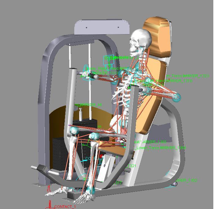

82


83 1


84 2
85 CHAPTER 4 THREE DIMENSIONAL MUSCULOSKELETAL MODELLING OF THE ABDOMINAL CRUNCH RESISTANCE TRAINING EXERCISE FOCUSING ON THE BIOMECHANICAL AND ANTHROPOMETRIC CONSIDERATIONS OF THE END-USER Kim Nolte 1, Pieter E. Krüger 1, & P. Schalk Els 2 1 Department of Biokinetics, Sport and Leisure Sciences, University of Pretoria, Pretoria, South Africa, 2 Department of Mechanical and Aeronautical Engineering, University of Pretoria, Pretoria, South Africa Abstract The aim of this study was to evaluate whether three dimensional (3D) musculoskeletal modelling could be effective in assessing the safety and efficacy of exercising on an abdominal crunch resistance training machine. The focus of the evaluation was on biomechanical and anthropometric considerations of the end-user. Three anthropometric cases were created; these represented a 5 th percentile female as well as a 50 th and 95 th percentile male based on body mass index (BMI). Resistance on the abdominal crunch machine was set at fifty percent of peak isokinetic force (trunk flexion/extension) for each anthropometric case, four repetitions were performed. Results indicated that the default model of the Lifemodeler TM software was reasonably successful in evaluating the abdominal crunch resistance training exercise. No adjustments had to be made to the default model in order to solve the forward dynamics simulations. The modelling was able to indicate high risk for back injury when performing the abdominal crunch exercise as a result of the unacceptable intervertebral joint loading that occurs during the exercise. Individuals with small anthropometric dimensions such as some females and children cannot be accommodated suitably on the abdominal crunch resistance training machine which negatively impacts exercise posture and technique. Hip flexor muscle contribution in the 82
86 execution of the exercise for the 5 th percentile female was substantial thus reducing the efficacy of the exercise in isolating the abdominal muscles. Keywords: Resistance training equipment, abdominal crunch, biomechanics, anthropometric, modelling, Lifemodeler TM, inverse dynamics, forward dynamics 83
87 Introduction This article constitutes the second article in a series of four. The series consists of three dimensional (3D) musculoskeletal modelling with a focus on biomechanical and anthropometric variables of four commonly used pieces of resistance training equipment. Participation in physical activity is encouraged by government agencies and physical activity experts because participation provides health, physical, mental, social, and economic benefits to the individual and community (Dennis and Finch, 2008). The increased popularity of, and participation in resistance training worldwide is indicative of the level of interest in benefits derivable from this type of training (Vaughn, 1989; Lou et al., 2007). Ironically, participation in any type of physical activity places the exerciser in situations in which injury is likely to occur. Improvement in exercise equipment design could reduce these hazards and therefore reduce the risk of injury (Dabnichki, 1998) as well as possibly increase the efficacy of the exercise. This study presents the musculoskeletal modelling of three anthropometric cases while exercising on a commercially available seated abdominal crunch resistance training machine. Thus, the primary aim of this study was to determine the efficacy of 3D musculoskeletal modelling in evaluating the abdominal crunch resistance training machine. The abdominal muscles are the major supporting muscles for the stomach area. They not only support and protect internal organs, but they aid the muscles of the lower back to properly align and support the spine for proper posture as well as in lifting activities (Beachle and Groves, 1992). The abdominals operate as an integrated functional unit, which helps maintain optimal spinal kinematics. When working efficiently, the abdominals offer sagittal, frontal, and transverses plane stabilization by controlling forces that reach the lumbo-pelvic-hip complex (Prentice, 2010). The abdominal wall muscles are different from other muscles, they do not go from bone to bone but attach onto an aponeurosis (fascia) around the rectus abdominis area. They are the external oblique abdominal, internal oblique abdominal, and transversus abdominis (Floyd, 2009). There are several 84
88 exercises for the abdominal muscles, such as bent-knee sit-ups, crunches, isometric contractions as well as exercises using specialized equipment and resistance training machines (McGill, 1995; Nieman, 2007). Controversy remains as to which exercise method best activates the muscles of the abdomen and minimizes potentially harmful or excessive joint tissue loading (McGill, 1995). A variety of selected abdominal exercises are required to sufficiently challenge the abdominal muscles and that these exercises will differ to best meet the different training objectives of the individual (Axler and McGill., 1997). Methods Equipment A 3D musculoskeletal full body model was created using LifeModeler software and incorporated into a multibody dynamics model of the abdominal crunch machine modelled in MSC ADAMS (Figure 1). The LifeModeler software runs as a plug-in on the MSC ADAMS software. LifeModeler TM software has previously been used in studies in the fields of sport, exercise and medicine (Schillings et al., 1996; Rietdyk and Patla., 1999; Hofmann et al., 2006; Agnesina et al., 2006; De Jongh, 2007; Olesen et al., 2009). It was decided to evaluate a default model as generated through the software. This model consists of 19 segments including a base set of joints for each body region. Specifically, the spine does not consist of individual vertebrae but rather of various segments that represent different regions of the vertebral column with joints between these segments. The default model has a full body set of 118 muscle elements attached to the bones at anatomical landmarks, which includes most of the major muscle groups in the body. Closed loop simple muscles were modelled. Closed loop muscles contain proportional-integral-differential (PID) controllers. The PID controller algorithm uses a target length-time curve to generate the muscle activation and the muscles follow this curve. Because of this approach, an inverse dynamics simulation using passive recording muscles is required prior to simulation with closed loop muscles. Simple muscles fire with no constraints 85
89 except for the physiological cross-sectional area (pcsa), which designates the maximum force a muscle can exert. The graphs of simple muscle activation curves will generally peak at a flat force ceiling value (Biomechanics research group, 2006). Figure 1: 3D musculoskeletal modelling of the abdominal crunch resistance training machine and 95 th percentile male musculoskeletal model using LifeModeler TM and MSC ADAMS software. Musculoskeletal full body human and the abdominal crunch computer aided design (CAD) models Three anthropometric cases were created for each piece of equipment. The human models were created using the GeBOD anthropometry database (default LifeModeler database) but were based on body mass index (BMI) data obtained from RSA-MIL-STD 127 Vol 1 (2004). This standard is a representative anthropometry standard of the South African National Defence Force (SANDF) 86
90 which is kept current by a yearly sampling plan and is an accurate representation of the broader South Africa population. Bredenkamp (2007) described a process to characterize the body forms of SANDF males and females. Body form variances described by two principle components (PC s) for the SANDF males and two PC s for SANDF females were included in the modelling process. Positive and negative boundary cases of each PC, representing the boundary conditions to be accommodated in design (Gordon and Brantley, 1997), identified the total range of four male and four female models. It was decided to use the cases representing the smallest female as well as an average and large male for the three anthropometric cases for this study. These cases could be seen as what are traditionally known as a 5 th percentile female, 50 th percentile male and a 95 th percentile male based on the BMI of each of these cases. Thus, for the purpose of building these biomechanical models, a correlation between BMI and functional body strength was assumed. Similar assumptions have previously been made in biomechanics full body model simulations (Rasmussen et al., 2007). A study by Annegarn et al. (2007) also verified scaled modelling strengths against actual functional body strengths and correlations ranged from 0.64 to This approach was followed in order to ensure that the equipment can accommodate an acceptable sample of the South African end-user population. A CAD model of the abdominal crunch resistance training machine was obtained from a South African exercise equipment manufacturing company. The model in a Parasolid file format was imported into the LifeModeler simulation software. The Adams software was used to create two design variables in order to adjust the external resistance (as selected by the amount of weights when using a selectorised resistance training machine) and to specify the radius of the cam over which the cable of an actual exercise machine would run in order to lift the selected resistance. This was possible since this machine employed a circular cam system however, this would not be possible with exercise machines employing non-circular cam systems, in order to attain better mechanical 87
91 advantage for the end-user. A special contact force (solid to solid) was created between the weights being lifted and the remainder of the weight stack during the simulation. A coupler joint was created linking the revolute joint (driver) of the lever arm attached to the abdominal crunch machine pad/cushion with the translational joint of the weight stack. The design variable created for the radius of the cam was referenced as the scale of the coupled joint (translational joint at weights). The design variable created for the mass of the weights was then adjusted according to the pre-determined resistance for each anthropometric case. The external resistance applied in the models was based on data obtained from Isokinetic testing results from trunk flexion (Perrin, 1993). Trunk flexion was selected as it most closely resembles the abdominal crunch movement. Torque (Nm) values obtained were converted to force values in Kilograms by adjusting for estimated lever length of the trunk of each anthropometric case. Fifty percent of the functional strength one repetition maximum (1RM) for each anthropometric case was used as this can be considered a manageable resistance to perform an exercise with appropriate form and technique for four repetitions. Simulation Extreme care was taken with the positioning of the musculoskeletal model onto the abdominal crunch machine to ensure technique, posture and positioning was correct according to best exercise principles (Table I). Furthermore, total manufacturer adjustability of the exercise machine was used in order to ensure correct positioning for each of the anthropometric cases. The following steps were performed in order to ensure realistic kinematics during the inverse dynamics simulations: 1) Positioning of the human model on the exercise equipment, 2) Adjustment of the posture to allow for the human machine interface to be created, 3) Creating the constraints between the human and machine, 4) Prescribing the motion of the repetitions, 5) Evaluation of the resultant kinematics, 6) Adjustment of joint positions until inverse dynamics 88
92 resulted in a realistic exercise movement. A bushing element was applied between the lower torso and the seat of the abdominal crunch machine as well as the two humeral bones and the abdominal crunch machine pad/cushion. Bushing elements were preferred to fixed joint elements because it allows for limited translational and rotational motion. Also, the amount of motion can be controlled by changing stiffness and damping characteristics in all three orthogonal directions. The inverse dynamics forward dynamics method was applied during the simulations. Inverse dynamics simulations are performed on models which are being manipulated by the use of motion agents or motion splines. During the inverse dynamics simulation, a rotational motion was applied to the revolute joint of the lever arm attached to the pad/cushion of the abdominal crunch machine in order to generate the required movement of the resistance training machine. This movement replicated the pulling (concentric) and resisting (eccentric) phase of the exercise. The time for the concentric phase was set at 1.33 seconds and the eccentric phase longer at 2.66 seconds to mimic conventional resistance training technique in which the downward phase is more deliberate to prohibit the use of momentum. The 1.33 second concentric phase included a STEP function approximation over 0.5 seconds to ensure a gradual start to the movement. The muscles of the model were trained during the inverse dynamics simulation in order to calculate the changes in muscle lengths to result in the required machine movement. After the inverse dynamics simulation was performed, the rotational motion was removed from the rotational joint of the lever arm of the abdominal crunch machine. The recorded muscle length changes and resulting joint movements were then used to drive the model during the forward dynamics simulation in the manner as developed through the inverse dynamics simulation. During the forward dynamics simulation the model is guided by the internal forces (muscle 89
93 length changes resulting in joint angulations and torques) and influenced by external forces (gravity, contact and determined exercise resistance). Table I. Exercise starting posture for the 3 anthropometric cases on the abdominal crunch machine. Results are presented for the sagittal, transverse and frontal planes (degrees). Note that F = flexion, E = extension, and AB = abduction. Joint 5 th percentile female 50 th percentile male 95 th percentile male Scapula 0.0; 0.0; ; 0.0; ; 0.0; 0.0 Shoulder 82.0(F); 0.0; (F); 0.0; (F); 0.0; 0.0 Elbow 90.0(F); 0.0; 90.0(F) 90.0(F); 0.0; 90.0(F) 90.0(F); 0.0; 90.0(F) Wrist 0.0; 0.0; ; 0.0; ; 0.0; 0.0 Hip 40.0(F); 0.0; 7.0(AB) 63.0(F); 0.0; 7.0(AB) 77.0(F); 0.0; 7.0(AB) Knee 20.0(F); 0.0; (F); 0.0; (F); 0.0; 0.0 Ankle 8.0(E); 0.0; (E); 0.0; (E); 0.0; 0.0 Upper neck 0.0; 0.0; ; 0.0; ; 0.0; 0.0 Lower neck 0.0; 0.0; ; 0.0; ; 0.0; 0.0 Thoracic 0.0; 0.0; ; 0.0; ; 0.0; 0.0 Lumbar 0.0; 0.0; ; 0.0; ; 0.0; 0.0 Data analysis The anthropometric dimensions and exercise postures of the musculoskeletal human models were visually assessed in relation to the dimensions and adjustability of the resistance training equipment in order to determine if all three anthropometric cases representative of the South African end-user population could comfortably be accommodated on the abdominal crunch resistance training machine. Key aspects included start and end exercise posture as well as maintaining correct technique throughout the exercise during the simulations. Start and end exercise posture evaluation entailed positioning of the axilla and upper arms (humerus) on the top of the abdominal crunch pad touching the chest at the sternum. The feet are supposed to be positioned on the provided supports with the hips flexed in order to protect the lower lumbar area from excessive strain during the exercise. Correct technique was assessed in terms of limited compensatory movements and performing the abdominal crunch through the full range of motion as determined by the inverse dynamics. 90
94 The kinematic and kinetic data from the simulations were analysed specifically in terms of peak muscular force production of the prime movers of the abdominal crunch exercise. Thus for the purpose of this study, efficacy of the equipment was assessed by evaluating whether the equipment exercised the muscles it was designed for, does the abdominal crunch machine exercise the primary abdominal muscles? Furthermore, the risk of injury to the musculoskeletal system of the exerciser was ascertained by comparison of measured forces with safe loading limits for joints of the lumbar and thoracic spine. Risk to both these structures are real especially during exercises that require spinal flexion and extension (with and without resistance) and or during execution of exercise with poor postures. Due to the nature of this study only basic descriptive statistics were performed by means of the STATISTICA software package (Statsoft). Results Table II presents the body mass and stature of the three anthropometric cases based on BMI data obtained from RSA-MIL-STD 127 Vol 1 (2004). Table III presents the external resistance the models had to overcome during the forward dynamics simulations, fifty percent of the functional strength 1RM for each anthropometric case was used for four repetitions. Table II. Anthropometric details of population groups studied. User population group Body mass (kg) Stature (mm) 5 th percentile female th percentile male th percentile male
95 Table III. User population strength data. User population group User population group exercise resistance (50% 1RM) kg 5 th percentile female 5 50 th percentile male th percentile male 24 Muscle force production (N) and contraction (shortening and lengthening) (mm) for the right side are reported on. Theoretically, the results of the left and right side should be similar. Force production (N) of the Erector spinae (ER), Rectus abdominis (RA), Oblique (O) as well as the hip flexor [Psoas major (PM) and Iliacus (I)] muscles are presented in Tables IV and V, respectively. Maximum force production was greatest for the O muscle in comparison to the RA muscle for all three anthropometric cases (Figure 2). The 5 th percentile female exerted the most force for all muscles analysed and the 50 th percentile male the least, with the exception of the ES muscle which was slightly higher for the 50 th percentile male in comparison with the 95 th percentile male. The hip flexor muscles were only used by the 5 th percentile female, specifically the PM muscle. Table IV. Right Erector spinae, Rectus abdominis and Internal and External oblique muscles force production (N) results for the 3 anthropometric cases. Musculoskeletal model Muscles Mean (N) Min. Max. Erector spinae (ES) th percentile female Rectus abdominis (RA) Oblique (O) Erector spinae (ES) th percentile male Rectus abdominis (RA) Oblique (O) Erector spinae (ES) th percentile male Rectus abdominis (RA) Oblique (O)
96 Table V. Right Psoas major and Iliacus (hip flexors) muscle force production (N) results for the 3 anthropometric cases. Musculoskeletal model Muscles Mean (N) Min. Max. 5 th Psoas major (PM) percentile female Iliacus (I) th Psoas major (PM) percentile male Iliacus (I) th Psoas major (PM) percentile male Iliacus (I) Absolute muscle contraction (shortening and lengthening) (mm) results are presented in Table VI. The mean muscle contraction length for the ES, RA and O is greatest for the 95 th percentile male and smallest for the 5 th percentile female. The reverse is true for the PM and I muscles as the 5 th percentile female measured the greatest mean muscle contraction lengths. The mean muscle length is highest for the RA muscle in comparison with the O muscle and a similar trend was found with the PM muscle in comparison with the I muscle for the three anthropometric cases Tension (N) Time (seconds) 5th female 50th male 95th male Figure 2: Right Oblique muscle force (N) for the 3 anthropometric cases (4 repetitions). 93
97 Due to the involvement of the spinal column in the abdominal crunch exercise, torque (Nm) for the T12/L1 intervertebral joint (thoracic) and the L5/S1 intertervertebral joint (lumbar) in the sagittal plane are presented in Table VII. For all three anthropometric cases peak thoracic torque was greater than peak lumbar torque. The 5 th percentile female s peak thoracic torque was greater than that of the other two anthropometric cases as shown in Figure 3. Table VI. Right Erector spinae, Rectus abdominis, Oblique, Psoas major and Iliacus absolute contraction (mm) results for the 3 anthropometric cases. Musculoskeletal model Muscles Mean (mm) Min. Max. Erector spinae (ES) Rectus abdominis (RA) th percentile female Oblique (O) Psoas major (PM) Iliacus (I) Erector spinae (ES) Rectus abdominis (RA) th percentile male Oblique (O) Psoas major (PM) Iliacus (I) Erector spinae (ES) Rectus abdominis (RA) th percentile male Oblique (O) Psoas major (PM) Iliacus (I) Table VII. Lumbar and thoracic joint torque (Nm) results in the sagittal plane for the 3 anthropometric cases. Musculoskeletal model Spinal joint Mean (Nm) Min. Max. 5 th Thoracic spine percentile female Lumbar spine th Thoracic spine percentile male Lumbar spine th Thoracic spine percentile male Lumbar spine Results for the thoracic (T12/L1 intervertebral joint) and lumbar (L5/S1 intervertebral joint) spine compression and anterior/posterior (A/P) shear forces are presented in Tables VIII and XI, respectively. The peak thoracic and lumbar spine joint compression forces are greatest for the 5 th percentile female and least 94
98 for the 50 th percentile male (Figure 4 and 5). Peak thoracic spine joint compression forces are greater than the peak lumbar spine joint compression forces for all the anthropometric cases with the exception of the 5 th percentile female whose peak lumbar spine joint compression forces exceed her peak thoracic spine joint compression forces Torque (Nm) Time (seconds) 5th female 50th male 95th male Figure 3: Thoracic spine joint torque (Nm) in the sagittal plane for the 3 anthropometric cases (4 repetitions). Note: negative joint angle indicates trunk flexion. Table VIII. Thoracic and lumbar spine joint compression forces (N) for the 3 anthropometric cases. Note: positive values indicate forces in a superior direction and negative values indicate forces in an inferior direction. Musculoskeletal model Spinal joint Mean (N) Min. Max. 5 th Thoracic spine percentile female Lumbar spine th Thoracic spine percentile male Lumbar spine th Thoracic spine percentile male Lumbar spine
99 Force (N) Time (seconds) 5th female 50th male 95th male Figure 4. Thoracic spine joint compression forces (N) for the 3 anthropometric cases (4 repetitions) Force (N) Time (seconds) 5th female 50th male 95th male Figure 5. Lumbar spine joint compression forces (N) for the 3 anthropometric cases (4 repetitions). 96
100 Force (N) Time (seconds) 5th female 50th male 95th male Figure 6. Thoracic spine joint A/P shear forces (N) for the 3 anthropometric cases ( repetitions) Force (N) Time (seconds) 5th female 50th male 95th male Figure 7. Lumbar spine joint A/P shear forces (N) for the 3 anthropometric cases (4 repetitions). 97
101 Peak thoracic spine joint A/P shear forces are greater than peak lumbar spine joint A/P shear forces for all anthropometric cases (Table XI). The 5 th percentile female has the highest peak thoracic and lumbar spine joint A/P shear forces in comparison with the 50 th and 95 th percentile males (Figure 6 and 7). Table XI. Thoracic and lumbar spine joint anterior/posterior shear forces (N) for the 3 anthropometric cases. Note: positive values indicate forces in a posterior direction and negative values indicate forces in an anterior direction. Musculoskeletal model Spinal joint Mean (N) Min. Max. 5 th Thoracic spine percentile female Lumbar spine th Thoracic spine percentile male Lumbar spine th Thoracic spine percentile male Lumbar spine Discussion Our first relevant finding of this study was that the LifeModeler default model was adequate to solve the forward dynamics simulations for all the anthropometric cases. This was not the case for the previous study in which the seated biceps curl resistance training exercise was modelled. Three adjustments had to be made to the musculoskeletal models on the seated biceps curl machine before the forward dynamics simulations could be solved namely; 1) increase the pcsa of the three default elbow flexor muscles, 2) manipulate the muscle origins and insertions and 3) decrease the joint stiffness in the forward dynamics simulations. The reason for the adjustments not being necessary in this study could possibly be due to the fact that the trunk musculature of the default model is more comprehensive than that of the elbow and shoulder joints. The only relevant muscle that is omitted from the LifeModeler TM default model is the transversus abdominis. 98
102 Our second relevant finding was that the software was once again able to sufficiently indicate anthropometric differences with regards to the machine s engineered or manufactured adjustability as it did with the seated biceps curl machine. The anthropometric dimensions of the musculoskeletal models could be accommodated comfortably in relation to the dimensions and adjustability of the abdominal crunch machine except for the 5 th percentile female (Figure 8). The small female s feet could barely reach the foot rest and the abdominal crunch pad/cushion was positioned too high and therefore could not be accommodated adequately under her axilla. Furthermore, her lumbar (L5/S1) spine joint could not be aligned properly with the axis of rotation of the machine. As a result her movement on the abdominal crunch machine was negatively impacted as her thoracic spine movement appeared to be exaggerated during the execution of the exercise to the point where it resulted in highly improbable joint loads, possibly an artefact of the modelling process. The movement on the abdominal crunch machine can possibly be compared to a bent knee sit-up movement, in a study conducted by McGill (1995) the analysis of a bent knee sit-up showed that most of the flexion rotation movement takes place about the hips and not the spine. Rather the spine remains close to the isometric flexed posture throughout the dynamic sit-up cycle. Thus, a sit-up exercise may be considered an isometric flexion exercise as far as the trunk musculature is concerned. The 50 th and 95 th percentile males appeared to have produced trunk flexion at the lumbar sacral region rather than the unnatural flexion of the thoracic region as demonstrated by the female model. Figure 9 illustrates that the mismatch between the female model anthropometry and machine adjustability resulted in excessive thoracic spine movement so that the thoracic joint reached its range of motion limits. While the results suggests that the female is at increased risk for injury due to poor accommodation by the machine it is possible that the values obtained for muscle tensions and joint loads are exacerbated by an artefact in the modelling process most probably caused by the thoracic joint movement exceeding the default range of motion. 99
103 Furthermore, the large muscle lengths recorded specifically in the O muscle could also be an indication that there was exaggerated movement of the trunk rather than that of an isometric contraction in the small female although the other anthropometric cases recorded similar muscle lengths. Figure 8. 5 th percentile female s positioning on the abdominal crunch resistance training machine 100
104 Joint angle (degrees) Time (seconds) 5th female 50th male 95th male Figure 9. Thoracic joint angle ( ) for the 3 anthropometric cases (4 repetitions). Thirdly, the following relevant findings were made regarding the biomechanical evaluation in terms of exercise efficacy and injury risk. The O muscles in comparison with the RA muscles exerted more force during the exercise for all anthropometric cases. This result was not entirely expected as the O muscles are traditionally exercised using trunk rotation or twisting to the left and right which bring the oblique muscles into more active contraction (Floyd, 2009). The O muscles however, also aid in lumbar flexion and posterior pelvic rotation and thus could explain its significant contribution to the execution of the movement of the abdominal crunch exercise. In addition in a study conducted by McGill (1995) it was found that the RA muscles activity to be slightly lower in bent knee sit-ups as opposed to the straight leg variety, while the O muscles were activated to a greater level presumably to make up the moment deficit. Similar results were obtained in this study in comparison with McGill (1995) with regards to abdominal RA and O muscle force production measured by means of electromyography (EMG) during the straight leg sit-up such as 206N and 236N respectively. It must 101
105 be noted that Lifemodeler TM default model only consists of 1 pair of oblique muscles, the orientation of the muscles appear to resemble that of the External obliques. The ES muscle recruitment can be explained by means of its antagonistic role in relation to the RA and O muscles. In a study conducted on sit-ups it was found that the antagonist extensor moments are produced particularly by the thoracic extensors (Iliocostalis lumborum and Longissimus thoracis). Most of the extensor force was due to neural activation as well as due to passive elastic stretching (McGill, 1995). Usually when abdominal exercises are performed the exerciser tries to reduce the contribution of the hip flexors with regards to the execution of the movement. The most commonly recommended manner of reducing the contribution of these muscles is to bend or flex the hips as this shortens the iliopsoas muscle and other hip flexors thereby reducing their ability to produce force (Floyd, 2009). In addition, this action of the hips is supposed to reduce lumbar joint compression. However, Axler and McGill (1997) found this not to be the case as there were no differences observed in lumbar spine joint compression or the utilization of the hip flexor muscles in sit-ups performed with the legs bent versus with the legs straight. The positioning of the musculoskeletal model on the abdominal crunch resistance training machine in this study is such that the hips and knees are in a flexed position and results indicate that the Iliopsoas muscles did not significantly contribute to the movement with the exception of the 5 th percentile female. The high recorded PM muscle force production in the small female appear unrealistic and could be due to a combination of an artefact as well as poor accommodation of the model. There was much less hip flexion for the 5 th percentile female in comparison with that of the other two anthropometric cases. Therefore, the exercise was not successful in isolating the abdominal muscles of the small female. The 5 th percentile females force production for all studied muscles was the greatest in comparison with the other anthropometric cases. This result is not 102
106 unexpected as anatomical differences could be the reason for the greater force production in the small female such as a smaller lever arm, even although the resistance used for all three cases was proportionally calculated to correlate the anthropometric dimensions. Joint torque values obtained for the thoracic and lumbar spine in the 50 th and 95 th percentile males as well as lumbar spine torque values of the 5 th percentile female appear to be plausible when comparing the results to peak values obtained by means of isokinetic testing. Langrana and Lee (1984) report trunk flexion/extension values of 60 Nm and 95 Nm respectively in non-disabled female subjects and 136 Nm and 212 Nm respectively in non-disabled male subjects assessed in a seated position at 30 degrees per second. Bearing in mind that the values obtained in this study were not from maximal testing they were still substantially lower than the isokinetic values of Langara and Lee with the exception of the 5 th percentile female s thoracic spine torque values which were considerably higher. This once again could have resulted due to her poor positioning, on the abdominal crunch resistance training machine and thus alluding to her high injury risk profile. Abdominal exercises are prescribed for both the prevention and treatment of low back injury. However, these exercises sometimes appear to have hazardous effects on the spine. A study conducted by Axler and McGill (1997) with the purpose of identifying abdominal exercises that optimize the challenge to the abdominal muscles but impose minimal load penalty to the lumbar spine found that no single exercise optimally trained all of the abdominal muscles while at the same time incurring minimal intervertebral joint loads. Accurate assessment of the risk of spinal injuries during occupational, athletic/exercise and daily activities as well as subsequent design of effective prevention and treatment programmes depend among others, on an accurate estimation of trunk muscle forces and internal spinal loads (i.e., intervertebral disc compression and shear forces)(arjmand et al., 2009). Thus, an important aspect of this study involved 103
107 assessing the intervertebral joint loads. The intervertebral discs work as a viscoelastic system that absorb and distribute forces acting on the spine. When submitted to compressive forces the collagen fibres of the annulus fibrosus are deformed radially expelling fluid from the nucleus pulposus of the discs (Adams and Hutton, 1985). It is important to bear in mind when making this analysis and applying the information that the spine of the default model does not consist of all the individual vertebrae but rather of various segments that represent the different regions of the vertebral column with joints between these segments. Individualised vertebra and corresponding joints might produce different results. Previous research from the American National Institute for Occupational Safety and Health (NIOSH) recommends that spinal compression forces should not exceed 3.4 kn to avoid injury. However there is a very real threat of musculoskeletal injury before this failure limit value has been reached (Snook and Ciriello, 1991; Cooper and Ghassemieh, 2007, Knapik and Marras, 2009). British standards (BS EN , 2002) recommend 600 N as the cut-off point for carrying masses, no further recommendations except time of exposure needs to be minimised and a preferred system requires optimal ergonomic position with reduced back bending posture are made. Therefore, the 5 th percentile female s lumbar and thoracic spine joint compression forces were far above the recommended failure limit of 3.4 kn and therefore she would be at certain risk for a back injury. The 50 th and 95 th percentile males thoracic and lumbar joint spine compression forces were also high and therefore could also be at risk for a back injury. The thoracic spine joint A/P shear forces appear to be higher than the lumbar spine joint A/P for the three anthropometric cases. Both thoracic and lumbar spine joint A/P shear forces for all three anthropometric cases are above the most commonly cited spine tolerance of 1000 N for shear force as stipulated by McGill (1996), with the exception of the 50 th and 95 th percentile males lumbar spine joint A/P shear forces. Thus, this exercise clearly places all three anthropometric cases at risk of injury especially the small female because of her 104
108 extremely high values recorded for both thoracic and lumbar spine joint A/P shear forces. It is important to note that the modelling does not take conditioning differences between individuals of similar anthropometric dimensions into account which can protect the individual against spinal loading. Furthermore, increased strength of trunk flexors and extensors muscles are thought to raise intra-abdominal pressure and to decrease spinal loading (Aspden, 1988). The results regarding the spine reaction forces are not surprising. Predictions of compressive load on the low back were found to be substantial during both isometrically held sit-ups and dynamic sit-ups with minimal acceleration components by Axler and McGill (1997). Therefore, forces on the back during a resistance exercise such as this can be expected to put substantial strain on the back especially if positioning is not adequate as with the 5 th percentile female. Lastly, it should be noted when evaluating an exercise in terms of efficacy and injury risk it is sometimes useful to compare various exercise techniques, different exercises for the same muscle groups as well as different manufacturer s equipment for the same exercise. Conclusion It can be concluded that the default model of the Lifemodeler TM software was reasonably successful in evaluating the abdominal crunch resistance training exercise. No adjustments had to be made to the default model in order to solve the forwards dynamics simulations. The most significant value of the abdominal crunch resistance training machine 3D musculoskeletal modelling was in demonstrating the unacceptable thoracic and lumbar spine joint compression and A/P forces which could place the exerciser at high risk for a back injury. Therefore, caution should be used when prescribing the exercise for the training of the abdominal muscles especially if the individual has a predisposing back problem or injury. In addition, individuals of small anthropometric dimensions such as some females and children cannot be accommodated suitably on the 105
109 machine which unfavourably influences exercise posture and technique which can further place the exerciser at increased risk for injury and decrease the efficacy of the exercise. Therefore, design adjustments to the abdominal crunch resistance training machine such as adapting the foot rest should be considered by the manufacturer. References Aspden, R.M. (1988). The spine as an arch. A new mathematical model. Spine, 13, Adams, M.A., and Hutton, W.C. (1985). Gradual disc prolapse. Spine, 10, Agnesina, G., Taiar, R., Havel, N., Guelton, K., Hellard, P., and Toshev, Y. (2006). BRG.LifeMOD TM modeling and simulation of swimmers impulse during a grab start. Proceedings of the 9 th symposium on 3D analysis of human movement. Valenciennes. Annegarn, J., Rasmussen, J., Savelberg, H.H.C.M., Verdijk, L.B., and Meijer, K. (2007) (Accessed 2008). Scaling strength in human simulation models. Arjmand, N., Gagnon, D., Plamondon, A., Shirazi-Adl, A., and Lariviére, C. (2009). Comparison of trunk muscle forces and spinal loads estimated by 2 biomechanical models. Clinical Biomechanics, 24, Axler, C.T., and McGill, S.M. (1997). Low back loads over a variety of abdominal exercises: searching for the safest challenge. Medicine and Science in Sports and Exercise, 29 (6),
110 Beachle, T.R., and Groves, B.R. (1992). Weight training: steps to success. Champaign: Human Kinetics. Biomechanics Research Group, Inc. (2006). LifeMOD biomechanics modeler manual. Bredenkamp, K. (2007). The characterisation of the male and female body forms of the SANDF. ERGOTECH Document P0683/2007/01. Centurion: ERGOnomics TECHnologies. South Africa. BS EN : (2002). Safety of machinery Human physical performance Part 3: Recommended force limits for machinery operations. London: British Standards Institute. Cooper, G., and Ghassemieh, E. (2007). Risk assessment of patient handling with ambulance stretcher systems (ramp / winch), easy-loader, tail-lift using biomechanical failure criteria. Medical Engineering & Physics, 29, Dabnichki, P. (1998). Biomechanical testing and sport equipment design. Sports Engineering, 1, De Jongh, C. (2007). Critical evaluation of predictive modelling of a cervical disc design, Unpublished Masters thesis, University of Stellenbosch. Dennis, R., and Finch, C. (2008). Sports injuries. International Encyclopaedia of Public Health Floyd, R.T. (2009). Manual of structural kinesiology (17 th McGraw-Hill. Ed). New York: 107
111 Gordon, C.C., and Brantley, J.D. (1997). Statistical modelling of population variation in the head and face. The design and integration of helmet systems International Symposium Proceedings. Massachusetts, USA. Hofmann, M., Danhard, M., Betzler, N., Witte, K., and Edelmann, J. (2006). Modelling with BRG.lifeMOD TM in sport science. International Journal of Computer Science in Sport, 5. Knapik, G.G., and Marras, W.S. (2009). Spine loading at different lumbar levels during pushing and pulling. Ergonomics, 52(1): Langara, N.A., and Lee, C.K. (1984). Isokinetic evaluation of trunk muscles. Spine, 9, Lou, S.L., Chen, Y.C., You, J.Y., and Hsu, C.K. (2007). Functional evaluation of elliptical trainer with human motion analysis, Proceedings of 2007 International Society of Biomechanics conference, Taiwan. McGill, S.M. (1995). The mechanics of torso flexion: sit-ups and standing dynamic flexion manoeuvres. Clinical Biomechanics. 10(4), McGill, S.M. (1996). Searching for the safe biomechanical envelope for maintaining healthy tissue, Pre-Meeting workshop, International Society for the Study of the Lumbar Spine: The Contribution of Biomechanics to the prevention and treatment of low back pain, University of Vermont, June 25. Nieman, D.C. (2007). Exercise testing and prescription: health-related approach (6 th Ed.). New York: McGraw-Hill. National Institute for Occupational Safety and Health. (1997). Musculoskeletal disorders and workplace factors: a critical review of epidemiologic evidence for 108
112 work-related musculoskeletal disorders of the neck, upper extremity, and low back. US Department of Health and Human Services (DHHS) Public Health Service, Centres for Disease Control. Cincinnati: National Institute for Occupational Safety and Health Division of Biomedical of Behavioural Science. Olesen, C.G., Andersen, M.S., Rathleff, M.S., de Zee, M., and Rasmussen, J. (2009). Understanding the biomechanics of medial tibial stress syndrome A simulation study using a musculoskeletal model. Proceedings of the 2009 International Society of Biomechanics. Cape Town. Perrin, D.H. (1993). Isokinetic exercise and assessment. Champaign: Human Kinetics. Prentice, W.E. (2010). Rehabilitation techniques for sports medicine and athletic training. New York: McGraw-Hill. Rasmussen, J., and de Zee, M., Damsgaard, M., Christensen, S.T., Marek, C. and Siebertz, K. (accessed 2007). A general method for scaling musculoskeletal models. Rietdyk, S., and Patla, A.E. (1999). Context-dependent reflex control: Some insights into the Role of Balance. Experimental Brain Research. 119, RSA-MIL-STD-127. (2004). Ergonomic design: Anthropometry and environment. RMSS Document, 1, Schillings, A.M., Van Wezel, B.M., and Duysens, J. (1996). Mechanically induced stumbling during human treadmill walking. Journal of Neuroscience Methods, 67,
113 Snook, S.H., and Ciriello, V.M. (1991). The design of manual handling tasks: revised tables of maximum acceptable weights and forces. Ergonomics, 34: Vaughn, C.L. (1989). Biomechanics of sport. Florida: CRC Press. 110
114 CHAPTER 5 THREE DIMENSIONAL MUSCULOSKELETAL MODELLING OF THE SEATED ROW RESISTANCE TRAINING EXERCISE FOCUSING ON THE BIOMECHANICAL AND ANTHROPOMETRIC CONSIDERATIONS OF THE END-USER Kim Nolte 1, Pieter E. Krüger 1, & P. Schalk Els 2 1 Department of Biokinetics, Sport and Leisure Sciences, University of Pretoria, Pretoria, South Africa, 2 Department of Mechanical and Aeronautical Engineering, University of Pretoria, Pretoria, South Africa Abstract The aim of this study was to evaluate whether three dimensional (3D) musculoskeletal modelling could be effective in assessing the safety and efficacy of exercising on a seated row resistance training machine. The focus of the evaluation was on biomechanical and anthropometric considerations of the enduser. Three anthropometric cases were created; these represented a 5 th percentile female as well as a 50 th and 95 th percentile male based on body mass index (BMI). Resistance on the seated row machine was set at fifty percent of the functional strength one repetition maximum (1RM) for each anthropometric case, two repetitions were performed. Results indicate that the default model of the Lifemodeler TM software has important limitations which should be taken into consideration when being used to evaluate exercise equipment. Adjustments had to be made to the model in order to solve the forward dynamics simulations and as a result no muscle forces or contraction values were obtained. This negatively influenced the value of the results as these parameters are important when analysing an exercise. The seated row resistance training machine s engineered or manufactured adjustability was sufficient as it appeared to accommodate the three anthropometric cases adequately so that no substantial injury risk was established for this exercise. 111
115 Keywords: Resistance training equipment, seated row, biomechanics, anthropometric, modelling, Lifemodeler TM, inverse dynamics, forward dynamics 112
116 Introduction This article constitutes the third article in a series of four. The series consists of three dimensional (3D) musculoskeletal modelling with a focus on biomechanical and anthropometric variables of four commonly used pieces of resistance training equipment. The advancement in computer technology and data processing capability has allowed the improvement of modelling software to a point where dynamic problems can now be simulated and analysed in a digital environment (Kim and Martin, 2007; Wagner et al., 2007; Zenk et al., 2005). Furthermore, computer simulations allow for the exploration of the limitations of human movement systems without endangering human subjects (Luttgens et al., 1992). With the capability to simulate musculoskeletal human models interacting with mechanical systems many questions concerning the effects of the resistance training equipment on the body can be studied. This study presents the musculoskeletal modelling of three anthropometric cases while exercising on a seated row resistance training machine. Thus, the primary aim of this study was to determine the efficacy of 3D musculoskeletal modelling in evaluating resistance training equipment design such as the seated row resistance training machine. In recent years, the popularity of dynamic resistance training has risen. This type of training is suitable for developing muscular fitness of men and women of all ages, as well as children (Heyward, 2004). The seated row forms the basis of many land-based training programmes for athletes, more specifically rowers. However, it is also often included as part of strength training programmes for non-athletes. It is an effective exercise to strengthen the musculature of the upper back. The primary joint movements for this exercise are shoulder extension and elbow flexion and thus the prime movers include the Latissimus dorsi and the Biceps brachii muscles (Heyward, 2004). Other important muscles 113
117 involved in the seated row exercise are the Posterior deltoids, Trapezius and Rhomboideus muscle groups (Floyd, 2009). In terms of understanding the biomechanics associated with various resistance training exercises, a great deal of literature has investigated the kinetics and kinematics associated with the bench press, squat and Olympic lifts. Therefore, it would appear as there is a preoccupation of researchers with extension type tasks and very little attention is given to other movements (Cronin et al, 2007). Furthermore, much of the available research consists of rowing ergometer analysis rather than the seated row resistance exercise. Methods Equipment A 3D musculoskeletal full body model was created using LifeModeler software and incorporated into a multibody dynamics model of the seated row resistance machine modelled in MSC ADAMS (Figure 1). The LifeModeler software runs as a plug-in on the MSC ADAMS software. LifeModeler TM software has previously been used in studies in the fields of sport, exercise and medicine (Schillings et al., 1996; Rietdyk and Patla, 1999; Hofmann et al., 2006; Agnesina et al., 2006; De Jongh, 2007; Olesen et al., 2009). It was decided to evaluate a default model as generated through the software. This model consists of 19 segments including a base set of joints for each body region. Specifically, the spine does not consist of individual vertebrae but rather of various segments that represent different regions of the vertebral column with joints between these segments. Furthermore, the default model has a full body set of 118 muscle elements attached to the bones at anatomical landmarks, which includes most of the major muscle groups in the body. Closed loop simple muscles were modelled. Closed loop muscles contain proportional-integral-differential (PID) controllers. The PID controller algorithm uses a target length-time curve to generate the muscle activation and the muscles follow this curve. Because of this approach, an inverse dynamics simulation using passive recording muscles is required prior to simulation with closed loop muscles. Simple muscles fire with no 114
. Figure 1.")
118 constraints except for the physiological cross-sectional area (pcsa), which designates the maximum force a muscle can exert. The graphs of simple muscle activation curves will generally peak at a flat force ceiling value (Biomechanics research group, 2006). Figure 1. 3D musculoskeletal modelling of the seated row resistance training machine and 50 th percentile male musculoskeletal model using LifeModeler TM and MSC ADAMS software. Musculoskeletal full body human and seated row computer aided design (CAD) models Three anthropometric cases were created for each piece of equipment. The human models were created using the GeBOD anthropometry database (default LifeModeler database) but were based on body mass index (BMI) data obtained from RSA-MIL-STD 127 Vol 1 (2004). This standard is a representative anthropometry standard of the South African National Defence Force which is 115
119 kept current by a yearly sampling plan and is an accurate representation of the broader South Africa population. Bredenkamp (2007) described a process to characterize the body forms of SANDF males and females. Body form variances described by two principle components (PC s) for the SANDF males and two PC s for SANDF females were included in the modelling process. Positive and negative boundary cases of each PC, representing the boundary conditions to be accommodated in design (Gordon and Brantley, 1997), identified the total range of four male and four female models. It was decided to use the cases representing the smallest female as well as an average and large male for the three anthropometric cases for this study. These cases could be seen as what are traditionally known as a 5 th percentile female, 50 th percentile male and a 95 th percentile male based on the BMI of each of these cases. Thus, for the purpose of building these biomechanical models, a correlation between BMI and functional body strength was assumed. Similar assumptions have previously been made in biomechanics full body model simulations (Rasmussen et al., 2007). A study by Annegarn et al. (2007) also verified scaled modelling strengths against actual functional body strengths and correlations ranged from 0.64 to This approach was followed in order to ensure that the equipment can accommodate an acceptable sample of the South African end-user population. A CAD model of the seated row resistance training machine was obtained from a South African exercise equipment manufacturing company. The model in a Parasolid file format was imported into the LifeModeler simulation software. The Adams software was used to create two design variables in order to adjust the external resistance (as selected by the amount of weights when using a selectorised resistance training machine) and to specify the radius of the cam over which the cable of an actual exercise machine would run in order to lift the selected resistance. This was possible since this machine employed a circular cam system however, this would not be possible with exercise machines employing non-circular cam systems, in order to attain better mechanical 116
120 advantage for the end-user. A special contact force (solid to solid) was created between the weights being lifted and the remainder of the weight stack during the simulation. A coupler joint was created linking the revolute joint (driver) of the lever arm attached to the handle bars with the translational joint of the weight stack. The design variable created for the radius of the cam was referenced as the scale of the coupled joint (translational joint at weights). The design variable created for the mass of the weights was then adjusted according to the predetermined resistance for each anthropometric case. The external resistance applied in the models was based on data obtained from RSA-MIL-STD 127 Vol 5 (2001). This database consists of a range of human functional strength measurement variables for SANDF males and females. Due to its representivity this standard may be considered an accurate representation of the functional body strength of the South Africa population (RSA-MIL-STD- 127, 2001). Furthermore, functional strength data was used from activities that most closely resembled the movements of the exercise as well as the muscle groups used during such movement. Fifty percent of the functional strength one repetition maximum (1RM) for each anthropometric case was used as this can be considered a manageable resistance to perform an exercise with appropriate form and technique for two repetitions. Simulation Extreme care was taken with the positioning of the musculoskeletal model onto the seated row machine to ensure technique, posture and positioning was correct according to best exercise principles (Table I). Optimal positioning of the models on the equipment required that there was approximately 90 degrees of shoulder flexion with slight elbow flexion that resulted in the hands finally being just higher than the elbows for all the anthropometric cases. This would be considered the correct posture for this exercise and resulted in the handle height being just below shoulder level for all the cases. Furthermore, total manufacturer adjustability of the exercise machine was used in order to ensure correct 117
121 positioning for each of the anthropometric cases. The following steps were performed in order to ensure realistic kinematics during the inverse dynamics simulations: 1) Positioning of the human model on the exercise equipment, 2) Adjustment of the posture to allow for the human machine interface to be created, 3) Creating the constraints between the human and machine, 4) Prescribing the motion of the repetitions, 5) Evaluation of the resultant kinematics, 6) Adjustment of joint positions until inverse dynamics resulted in a realistic exercise movement. Bushing elements were used to secure the chest to the chest pad/cushion as well as the lower torso to the seat and spherical joints were used to connect the hands to the handle bars of the seated row machine. Bushing elements were preferred to fixed joint elements because it allows for limited translational and rotational motion. Also, the amount of motion can be controlled by changing stiffness and damping characteristics in all 3 orthogonal directions. The original joints created in the biomechanical model had default joint parameters (Stiffness (K) =1E4, Dampening (C) =1000). Joints with such high joint stiffness are created to ensure a relatively rigid model that provides a stable and smooth motion when manipulated by motion splines. This is especially important during the movement of the model into the initial posture as well as to ensure smooth model motion during inverse dynamics. After the muscle lengths had been recorded in the inverse dynamics, the joint stiffness was changed to near zero, to represent actual stiffness in human joints. The inverse dynamics forward dynamics method was applied during the simulations. Inverse dynamics simulations are performed on models which are being manipulated by the use of motion agents or motion spines. During the inverse dynamics simulation, a rotational motion was applied to the revolute joint of the lever arm attached to the handle bars of the seated row machine in order to generate the required movement of the resistance training machine. This movement replicated the pulling (concentric) and resisting (eccentric) phase of the exercise. The time for the concentric phase was set at 1.66 seconds and the eccentric phase longer at 3.33 seconds to mimic conventional resistance training 118
122 technique in which the downward phase is more deliberate to prohibit the use of momentum. The 1.66 second concentric phase included a STEP function approximation over 0.5 seconds to ensure a gradual start to the movement. The joints forces of the model were recorded during the inverse dynamics simulation in order to calculate the changes in joint torques to result in the required machine movement. After the inverse dynamics simulation was performed, the rotational motion was removed from the rotational joint of the lever arm of the seated row machine. The resulting joint movements were then used to drive the model during the forward dynamics simulation in the manner as developed through the inverse dynamics simulation. During the forward dynamics simulation the model is guided by the internal forces (muscle length changes resulting in joint angulations and torques) and influenced by external forces (gravity, contact and determined exercise resistance). It is important to note that changes had to be made to the LifeModeler TM default model in order to solve the models with plausible kinematics during the forward dynamics simulations. Considering the research problem the detail of these changes will be discussed under the discussions section. All results presented are derived from the forward dynamics simulations after these changes to the default model were made. 119
123 Table I. Exercise starting posture for the 3 anthropometric cases on the seated row machine. Where applicable the joint angles refer to bi-lateral joints. Results are presented for the sagittal, transverse and frontal planes (degrees). Note that F = flexion, E = extension, IR = internal rotation and AB = abduction. Joint 5 th percentile female 50 th percentile male 95 th percentile male Scapula 0.0; 0.0; ; 0.0; ; 0.0; 0.0 Shoulder 85.0(F); 5.0(IR); 7.0(AB) 85.0(F); 5.0(IR); 4.5(AB) 85.0(F); 5.0(IR); 2.5(AB) Elbow 15.0(F); 10.0(IR); (F); 10.0(IR); (F); 10.0(IR); 0.0 Wrist 0.0; 0.0; ; 0.0; ; 0.0; 0.0 Hip 30.0(F); 0.0; (F); 0.0; (F); 0.0; 0.0 Knee 30.0(F); 0.0; (F); 0.0; (F); 0.0; 0.0 Ankle 0.0; 0.0; (E); 0.0; (E); 0.0; 0.0 Upper neck 0.0; 0.0; ; 0.0; ; 0.0; 0.0 Lower neck 0.0; 0.0; ; 0.0; ; 0.0; 0.0 Thoracic 0.0; 0.0; ; 0.0; ; 0.0; 0.0 Lumbar 15.0(F); 0.0; (F); 0.0; (F); 0.0; 0.0 Data analysis The anthropometric dimensions and exercise postures of the musculoskeletal human models were visually assessed in relation to the dimensions and adjustability of the resistance training equipment in order to determine if all three anthropometric cases representative of the South African end-user population could comfortably be accommodated on the seated row resistance training machine. Key aspects included start and end exercise posture as well as maintaining correct technique throughout the exercise during the simulations. The kinematic and kinetic data from the simulations were analysed specifically in terms of exercise efficacy and peak muscular and joint force production of the prime movers of the seated row exercise. Furthermore, the risk of injury to the musculoskeletal system of the exerciser was ascertained by comparison of measured forces with safe loading limits for joints of the lumbar and thoracic spine. The dynamic mode of analysis includes all the aspects of motion in the calculation of joint forces and internal stresses, including the effects introduced by changing velocity and acceleration components (Wagner et al., 2007). Different joint loading criteria were derived using biomechanical research taking into consideration the posture and anthropometry (Cooper and Ghassemieh, 120
124 2007). However, criteria for determining whether a particular task or exercise is safe based on tissue-level stresses are available for only a small number of tissues and loading regimes (e.g. lower back motion segments in compression) (Wagner et al, 2007). Due to the nature of this study only basic descriptive statistics were performed by means of the STATISTICA software package (Statsoft). Results Three anthropometric cases created for each piece of equipment based on BMI data obtained from RSA-MIL-STD 127 Vol 1 (2004) were used for the study and results were assessed (Table II). Table III represents the external resistance applied in the models, fifty percent of the functional strength 1RM for each anthropometric case was used for two repetitions. Table II. Anthropometric details of population groups studied (RSA-MIL-STD, Vol 1, 2004). User population group Body mass (kg) Stature (mm) 5 th percentile female th percentile female th percentile male Table III. User population strength data (RSA-MIL-STD, Vol 5, 2001). User population group User population group exercise resistance (50% 1RM) kg 5 th percentile female th percentile male th percentile male 30 Due to the involvement of wrist, elbow and shoulder joints in the seated row exercise, torque values for these joints are presented in Table IV. Values for the 121
125 right side of the body are reported on as theoretically the values for the left and right side should be similar. The 95 th percentile male recorded the highest peak joint torque values for the three joints (Figures 2, 3 and 4). The 50 th percentile male s peak elbow and wrist torque values were the lowest. The peak shoulder torque values of the 5 th percentile female and 50 th percentile male were similar and were lower than the 95 th percentile males values (Figure 4). For the three anthropometric cases the peak shoulder joint torque values were the lowest, followed by the wrist and the greatest for the elbow. Table IV. Right wrist, elbow and shoulder joint torque (Nm) results in the sagittal plane for the 3 anthropometric cases. Note that the joint torque values presented in the figures are in Nmm due to the default units of the modelling software. Musculoskeletal model Joint Mean (Nm) Min. Max. 5 th percentile female 50 th percentile male 95 th percentile male Wrist Elbow Shoulder Wrist Elbow Shoulder Wrist Elbow Shoulder
126 Torque (Nmm) Time (seconds) 5th female 50th male 95th male Figure 2. Sagittal right wrist joint torque (Nmm) for the 3 anthropometric cases (2 repetitions) Torque (Nmm) Time (seconds) 5th female 50th male 95th male Figure 3. Sagittal right elbow joint torque (Nmm) for the 3 anthropometric cases (2 repetitions). 123
127 Torque (Nmm) Time (seconds) 5th female 50th male 95th male Figure 4. Sagittal right shoulder joint torque (Nmm) for the 3 anthropometric cases (2 repetitions). The seated row exercise is a multi-joint exercise thus movement in the sagittal plane of the shoulder, elbow and wrist (right side) are reported on (Table V). The least movement occurred at the wrist joint, followed by the shoulder joint with the most movement occurring at the elbow joint for the three anthropometric cases. Range of motion of the 5 th percentile female was the least for the three joints. Range of motion was the greatest for the 95 th percentile male in the wrist and shoulder joint. Elbow joint range of motion was greatest for the 50 th percentile male (Figure 5). 124
128 Table V. Sagittal right wrist, elbow and shoulder joint angle ( ) Musculoskeletal model Joint Mean (degrees) Min. Max. Wrist th percentile female Elbow Shoulder Wrist th percentile male Elbow Shoulder Wrist th percentile male Elbow Shoulder Joint angle (degrees) Time (seconds) 5th female 50th male 95th male Figure 5. Sagittal right elbow angle ( ) for the 3 anthropometric cases (2 repetitions). Note: negative joint angle indicates elbow flexion. Results for the thoracic (T12/L1 intervertebral joint) and lumbar (L5/S1 intervertebral joint) spine compression and anterior/posterior (A/P) shear forces are presented in Tables VI and VII respectively. Peak thoracic spine joint compression forces were greatest for the 50 th percentile male, followed by the 95 th percentile male and were lowest in the 5 th percentile female (Figure 6). There was a similar trend in the peak lumbar spine joint compression forces 125
129 (Figure 7). In all anthropometric cases the peak lumbar spine joint compression forces were greater than the peak thoracic spine joint compression forces. Table VI. Thoracic and lumbar spine joint compression forces (N) for the 3 anthropometric cases. Note: positive values indicate forces in a superior direction and negative values indicate forces in an inferior direction. Musculoskeletal model Spinal joint Mean (N) Min. Max. 5 th Thoracic spine percentile female Lumbar spine th Thoracic spine percentile male Lumbar spine th Thoracic spine percentile male Lumbar spine Force (N) Time (seconds) 5th female 50th male 95th male Figure 6. Thoracic spine compression forces (N) for the 3 anthropometric cases (2 repetitions). 126
130 Force (N) Time (seconds) 5th female 50th male 95th male Figure 7. Lumbar spine compression forces (N) for the 3 anthropometric cases (2 repetitions). The 95 th and 50 th percentile males recorded similar peak thoracic and lumbar spine A/P shear forces. The 5 th percentile females peak thoracic spine and lumbar A/P shear forces were the least in comparison with the other two anthropometric cases (Figure 8). For all cases the peak thoracic and lumbar spine A/P shear forces were equal. 127
131 Force (N) Time (seconds) 5th female 50th male 95th male Figure 8. Lumbar spine anterior/posterior (A/P) shear forces (N) for the 3 anthropometric cases (2 repetitions). Table VII. Thoracic and lumbar spine joint anterior/posterior (A/P) shear forces (N) for the 3 anthropometric cases. Note: positive values indicate forces in a posterior direction and negative values indicate forces in an anterior direction. Musculoskeletal model Spinal joint Mean (N) Min. Max. 5 th Thoracic spine percentile female Lumbar spine th Thoracic spine percentile male Lumbar spine th Thoracic spine percentile male Lumbar spine The results for wrist and elbow joint A/P shear forces are presented in Table VIII. Peak wrist and elbow joint A/P shear forces were lowest for the 50 th percentile male and highest for the 95 th percentile male (Figure 9). Peak wrist A/P shear forces were slightly lower than elbow shear forces for all the anthropometric cases. 128
132 Table VIII. Right wrist and elbow joint anterior/posterior (A/P) shear forces (N) for the 3 anthropometric cases. Note: positive values indicate forces in a posterior direction and negative values indicate forces in an anterior direction. Musculoskeletal model Joint Mean (N) Min. Max. 5 th Wrist percentile female Elbow th Wrist percentile male Elbow th Wrist percentile male Elbow Force (N) Time (seconds) 5th female 50th male 95th male Figure 9. Right elbow anterior/posterior (A/P) shear forces (N) for the 3 anthropometric cases (2 repetitions). Discussion Firstly, it can be concluded from this study that the LifeModeler default model was not adequate to solve the forward dynamics simulations for any of the anthropometric cases. For the evaluation of the seated biceps curl exercise (first article in the series) the forward dynamics simulations could also only be solved 129
133 after a number of adjustments had been made to the model such as increasing pcsa of the muscles, manipulating muscle origins and insertions as well as decreasing the joint stiffness in the forwards dynamics simulations. All of these adjustments were implemented in order to solve the simulation without any success. Possible reasons for this could include the degrees of freedom involved in a multi joint exercise involving highly mobile joints such as the shoulder. Furthermore it could be that additional musculature is required to provide more stability in the shoulder joint during the forward dynamics simulations. In this study in order to solve this problem the joint angulations recordings in the inverse dynamics simulations were used to solve the forward dynamics simulations. This option creates a trained PID-servo type controller on the joint axis. The joint is commanded to track an angular history spline with a user-specified gain on the error between the actual angle and the commanded error. A user-specified derivative gain is specified to control the derivative of the error. Therefore, results for muscle forces (N) and contractions (shortening and lengthening) (mm) could not be analysed. Ideally these parameters should be analysed when evaluating an exercise. It appears that more complex, multi-joint or compound exercises that require too many degrees of freedom pose a problem for the default model and therefore models with more detailed musculature may be required to solve the forward dynamics simulations sufficiently. Important musculature required for the performance of the seated row exercise that are not included in the LifeModelerTM default model are the Rhomboideus major and minor and the Rotator cuff group (Supraspinatus, Infraspinatus, Teres minor and Subscapularis). It was not however within the scope of this study to produce anatomical detailed models but rather to evaluate the default model of the software. Secondly, the study did not indicate any obvious anthropometric differences with regards to the seated row machine s engineered or manufactured adjustability. All three anthropometric cases appeared to be positioned adequately on the seated row machine. This was not the case with the modelling performed on the 130
134 seated biceps curl and abdominal crunch machines, which demonstrated the inability of the machines to adjust appropriately to individuals with small anthropometric dimensions such as some females and children. As a result the exercise technique of the 5 th percentile female was negatively influenced and injury risk was increased for these exercises. Lastly, with regards to the biomechanical evaluation in terms of exercise efficacy and injury risk the following could be deduced from the study. Due to the fact that the forward dynamics simulations for this study was solved by recording the joint angulations changes during the inverse dynamics simulations and not muscle length changes, results for the muscle forces and contractions were not obtained and therefore could not be analysed. This negatively influenced the value of modelling with regards to evaluating the seated row exercise as muscle forces and contractions provide important information regarding the efficacy and injury risk of the exercise. Maximal joint torque values obtained for the wrist, elbow and shoulder appear to be plausible when comparing the values to peak values obtained by means of isokinetic testing at 60 degrees per second. For example wrist flexion/extension values of 13.8 Nm and 12.7 Nm respectively in non-disabled subjects (Van Swearingen, 1983). Elbow flexion/extension values of 36 Nm for both elbow flexion and extension in female college basketball players (Berg et al., 1985) and shoulder flexion/extension values of 77 Nm and 53 Nm for males and 38 Nm and 24 Nm for females respectively in a group of non-disabled (Nicholas et al., 1989). Joint torque values for the three joints evaluated were much lower than values obtained during peak isokinetic testing however it is important to bear in mind that the values obtained in this study were not obtained from maximal testing as with the isokinetic testing. The peak elbow joint torque was the highest recorded value for all the joints in the three anthropometric cases which was too be expected as the elbow joint is most involved in the seated row movement. 131
135 Not surprisingly, the joint range of motion (wrist, elbow and shoulder) used during the seated row exerciser was smallest for the 5 th percentile female and greatest for the 95 th percentile male. With the exception of the elbow joint range of motion which was greatest for the 50 th percentile male. It is not only important that correct technique be used for resistance exercises such as the seated row exercise but also that exercisers are performed through the full range of motion in order to decrease the likely of injury as well as get the maximum benefits of the exercise. It therefore appears that the three anthropometric models performed the seated row exercise through the full range of motion. Pushing and pulling as opposed to lifting activities might also be associated with significant risk to the low back (National Institute for Occupational Safety and Health, 1997, Hoozemans et al., 1988). The seated row exercise can be considered a pulling activity. It must be kept in mind that the cited research is primarily referring to occupational tasks however important similarities and conclusions can be drawn with exercises that use similar actions to occupational tasks and activities that require pulling. Furthermore, the spine of the default model does not consist of all the individual vertebrae but rather of various segments that represent the different regions of the vertebral column with joints between these segments. Individualised vertebra and corresponding joints might produce different results. In 2009 a study by Knapik and Marras (2009) found that there was greater compressive loading at all spine levels when performing pulling compared with pushing activities. Therefore, an individual performing a pulling exercise such as the seated row might be at more risk of a back injury as opposed to individuals performing a pushing exercise such as bench press specifically with regards to compressive loading. Previous research from the American National Institute for Occupational Safety and Health (NIOSH) recommends that spinal compression forces should not 132
136 exceed 3.4 kn to avoid injury. However there is a very real threat of musculoskeletal injury before this failure limit value has been reached (Snook and Ciriello, 1991; Cooper and Ghassemieh, 2007, Knapik and Marras, 2009). British standards (BS EN , 2002) recommend 600 N as the cut-off point for carrying masses, no further recommendations except time of exposure needs to be minimised and a preferred system requires optimal ergonomic position with reduced back bending posture are made. Therefore, all three anthropometric cases were well below the recommended failure limit of 3.4 kn. None of the anthropometric cases peak thoracic or lumbar compression forces were even near the recommended 600 N cut-off and therefore it may be postulated that all things considered the seated row exercise does not appear to cause excessive spinal compression forces that may put the individual at risk for an injury. Historically, spine compression in the lower lumbar spine has been the variable of interest for risk to the low back during work and exercise training. However, during horizontal force application (pulling of the seated row exercise), it is expected that shear forces within the spine increase dramatically due to the application of force in the hands and the reaction of the trunk musculature. Thus shear forces may represent the critical measure of risk (Knapik and Marras, 2009). According to Knapik and Marras (2009), in general, pushing activities impose greater potentially risky A/P shear forces upon the spine than pulling. Pushing imposed up to 23% greater A/P shear forces compared to pulling. Increases in shear forces were a result of the increased flexor muscle coactivity required for the activity. Although the spine A/P shear forces recorded were greater than the compression forces, the thoracic and lumbar spine joint A/P shear forces for the three anthropometric cases are also below the most commonly cited spine tolerance of 1000 N for shear force as stipulated by McGill (1996). It is important to note that even if the spine compression and A/P shear forces recorded were well within 133
137 the acceptable limits the modelling does not take into account the repetitive nature and accumulative effect of exercise. Furthermore, the resistance used was only 50% of each of the anthropometric cases estimated 1RM and therefore if exercises use a resistance closer to their maximum the loading values may exceed the acceptable limits. Handle height appears to affect the mechanical load at the low back and shoulder considerably and it is recommended that carts be designed and adjustable so that it is possible to push or pull at shoulder height (Hoozemans et al., 2004). The same principle can be applied to the seated row machine and the handle bars should be at approximately shoulder height, which was the case for the three anthropometric models and thus this could have assisted in reducing the spine loads, especially the A/P shear spine forces. Unfortunately, after conducting a literature search it became clear that information regarding A/P shear forces of the shoulder, elbow and wrist joints is scarce. However, the following information regarding handle height may be applicable in terms of reducing A/P shear forces on these joints during the seated row exercise. Handle height and the magnitude of force were found to be significantly related to the net moment at the shoulder. Net moments at the shoulder are kept low during pushing and pulling activities by keeping the wrist, elbow, and shoulder close to the line of action of the exerted force or by directing the exerted force such that the shoulder joint remains close to the line of action of the exerted force (Hoozemans et al., 1998). Thus, if the handle bars of the seated row resistance training machine are designed in such a way as to ensure correct alignment of the shoulder, elbow and wrist joints, it may assist in reducing the strain that these joints experience during this exercise, especially if a heavy resistance is used. Conclusion The limitations using the default model of the software was highlighted. Adjustments had to be made to the default model in order to solve the forward dynamics simulations using recorded joint angulations during the inverse 134
138 dynamics simulations. As a result no muscle (force and contraction) results could be obtained which negatively impacted the value of the modelling in evaluating the seated row exercise. The anthropometric dimensions of the end-users appeared to be adequately accommodated by the seated row s engineered or manufactured adjustability. Although pulling activities can pose a potential risk for spine injuries it did not appear as if the exercise put undue strain on the spinal structures when exercised with correct positioning and technique at an appropriate resistance. References Agnesina, G., Taiar, R., Havel, N., Guelton, K., Hellard, P., and Toshev, Y. (2006). BRG.LifeMOD TM modeling and simulation of swimmers impulse during a grab start. Proceedings of the 9 th symposium on 3D analysis of human movement. Valenciennes. Annegarn, J., Rasmussen, J., Savelberg, H.H.C.M., Verdijk, L.B., and Meijer, K. (2007) (accessed 2008). Scaling strength in human simulation models. Berg, K., Blank, D., and Muller, M. (1985). Muscular fitness profile of female college basketball players. Journal of Orthopaedic and Sports Physical Therapy, 7, Biomechanics Research Group, Inc. (2006). LifeMOD biomechanics modeler manual. Bredenkamp, K. (2007). The characterisation of the male and female body forms of the SANDF. ERGOTECH Document P0683/2007/01. Centurion: ERGOnomics TECHnologies. South Africa. 135
139 BS EN (2002). Safety of machinery Human physical performance Part 3: Recommended force limits for machinery operations. London: British Standards Institute. Cooper, G., and Ghassemieh, E. (2007). Risk assessment of patient handling with ambulance stretcher systems (ramp / winch), easy-loader, tail-lift using biomechanical failure criteria. Medical Engineering & Physics, 29, Cronin, J.B., Jones, J.V., and Hagstrom, J.T. (2007). Kinematics and kinetics of the seated row and implications for conditioning, Journal of Strength and Conditioning Research, 21(4), De Jongh, C. (2007). Critical evaluation of predictive modelling of a cervical disc design, Unpublished masters thesis, University of Stellenbosch. Floyd, R.T. (2009). Manual of structural kinesiology (17 th McGraw-Hill. Ed). New York: Gordon, C.C., and Brantley, J.D. (1997). Statistical modelling of population variation in the head and face. The design and integration of helmet systems International Symposium Proceedings. Massachusetts, USA. Heyward, V.H. (2004). Advanced fitness assessment and exercise prescription (5ht Ed.). Champaign: Human Kinetics. Hofmann, M., Danhard, M., Betzler, N., Witte, K., and Edelmann, J. (2006). Modelling with BRG.lifeMOD TM in sport science. International Journal of Computer Science in Sport, 5. Hoozemans, M.J.M., Kuijer, P.F.M., Kingma, I., Van Dieën, J.H., De Vries, W.H.K., van der Woude, L.H.V., Veefer, H.E.J., Van der Beek, A.J., and Frings- 136
140 Dresent, M.H.W. (2004). Mechanical loading of the low back and shoulders during pushing and pulling activities. Ergonomics, 47(1), 1-18 Hoozemans, M.J.M., Van der Beek, A.J., Frings-Dresen, M.H.W, Van Dijk, F.J.H., and Van der Woude, L, H, V. (1998). Pushing and pulling in relation to musculoskeletal disorders: a review of risk factors. Ergonomics, 41, Kim, H., and Martin, B.J. (2007). Estimation of body links transfer functions in vehicle vibration environment. Proceedings of the 2007 digital human modelling for design and engineering conference. Seattle. Knapik, G.G., and Marras, W.S. (2009). Spine loading at different lumbar levels during pushing and pulling. Ergonomics, 52(1): Luttgens, K., Deutsche, H., and Hamilton, N. (1992). Kinesiology: scientific basis of human motion (8 th Ed.). Dubuque: Brown and Benchmark. McGill, S.M. (1996). Searching for the safe biomechanical envelope for maintaining healthy tissue, Pre-Meeting workshop, International Society for the Study of the Lumbar Spine: The Contribution of Biomechanics to the prevention and treatment of low back pain, University of Vermont, June 25. National Institute for Occupational Safety and Health. (1997). Musculoskeletal disorders and workplace factors: a critical review of epidemiologic evidence for work-related musculoskeletal disorders of the neck, upper extremity, and low back. US Department of Health and Human Services (DHHS) Public Health Service, Centres for Disease Control. Cincinnati: National Institute for Occupational Safety and Health Division of Biomedical of Behavioural Science. 137
141 Nicholas, J.J., Robinson, L.R., Logan, A., and Robertson, R. (1989). Isokinetic testing in young non-athletic able-bodied subjects. Archives of Physical Medicine and Rehabilitation, 70, Olesen, C.G., Andersen, M.S., Rathleff, M.S., de Zee, M., and Rasmussen, J. (2009). Understanding the biomechanics of medial tibial stress syndrome a simulation study using a musculoskeletal model. Proceedings of the 2009 International Society of Biomechanics. Cape Town. Rasmussen, J., de Zee, M., Damsgaard, M., Christensen, S.T., Marek, C., and Siebertz, K. (accessed 2008). A general method for scaling musculo-skeletal models. Rietdyk, S., and Patla, A.E. (1999). Context-dependent reflex control: Some insights into the role of balance. Experimental Brain Research. 119, RSA-MIL-STD-127. (2001). Ergonomic Design: Biomechanics Specific functional body strength data standard. RMSS Document, 5, RSA-MIL-STD-127. (2004). Ergonomic design: Anthropometry and environment. RMSS Document, 1, Schillings, A.M., Van Wezel, B.M., and Duysens, J. (1996). Mechanically induced stumbling during human treadmill walking. Journal of Neuroscience Methods, 67, Snook, S.H., and Ciriello, V.M. (1991). The design of manual handling tasks: revised tables of maximum acceptable weights and forces. Ergonomics, 34:
142 Van Swearingen, J.M. (1983). Measuring wrist muscle strength. Journal of Orthopaedic and Sports Physical Therapy, 4, ). Wagner, D., Rasmussen, J., and Reed, M. (2007). Assessing the Importance of Motion Dynamics for Ergonomic Analysis of Manual Materials Handling Tasks using the AnyBody Modelling System. Proceedings of the 2007 Digital Human Modelling for Design and Engineering Conference. Seattle. Zenk, R., Franz, M., and Bubb, H. (2005). Spine load in the context of automotive seating. Proceedings of the 2007 digital human modelling for design and engineering conference. Seattle. 139
143 CHAPTER 6 THREE DIMENSIONAL MUSCULOSKELETAL MODELLING OF THE CHEST PRESS RESISTANCE EXERCISE FOCUSING ON THE BIOMECHANICAL AND ANTHROPOMETRIC CONSIDERATIONS OF THE END-USER Kim Nolte 1, Pieter E. Krüger 1, & P. Schalk Els 2 1 Department of Biokinetics, Sport and Leisure Sciences, University of Pretoria, Pretoria, South Africa, 2 Department of Mechanical and Aeronautical Engineering, University of Pretoria, Pretoria, South Africa Abstract The aim of this study was to evaluate whether three dimensional (3D) musculoskeletal modelling could be effective in assessing the safety and efficacy of exercising on a chest press resistance training machine. The focus of the evaluation was on biomechanical and anthropometric considerations of the enduser. Three anthropometric cases were created; these represented a 5 th percentile female as well as a 50 th and 95 th percentile male based on body mass index (BMI). Resistance on the chest press machine was set at fifty percent of the functional strength one repetition maximum (1RM) for each anthropometric case, two repetitions were performed. The results indicate that adjustments had to be made to the default model in order to solve the forward dynamics simulations using recorded joint angulations during the inverse dynamics simulations. As a result no muscle (force and contraction) results could be obtained which negatively impacted the value of the modelling in evaluating the chest press exercise. The anthropometric dimensions of the end-users appeared to be adequately accommodated by the chest press s engineered or manufactured adjustability. Although pushing activities can pose a potential risk for spine injuries it did not appear as if the exercise put undue strain on the spinal structures when exercised with correct positioning and technique at an 140
144 appropriate resistance. However, the wrist joint and cervical spine appear to be vulnerable areas during the chest press exercise due to the relatively high wrist torque values in comparison to other joints as well as the relatively high cervical compression loads recorded. To conclude, although important design elements and flaws were highlighted by the 3D modelling in this series, mathematical and computer modelling does have its limitations especially when the default model is used. Keywords: Resistance training equipment, chest press, biomechanics, anthropometric, modelling, Lifemodeler TM, inverse dynamics, forward dynamics 141
145 Introduction This article constitutes the fourth and last article in a series. The series consists of three dimensional (3D) musculoskeletal modelling with a focus on biomechanical and anthropometric variables of four commonly used pieces of resistance training equipment. Design of exercise equipment is a complicated task and warrants consideration of a series of biomechanical and ergonomics factors. Furthermore, there is inevitably increased loading on certain parts of the body due to the repetitive nature of exercises. Improvement in equipment design could reduce these hazards and offset such a negative effect on the body (Dabnichki, 1998). Currently, there is no regulation of exercise equipment design and production in South Africa. Therefore, a need exists to subject such pieces of equipment to evaluation methods of which the goal is to ensure the equipment s efficacy as well as the safety of the end-user. Resistance training has emerged as an essential part of the individual s programme to improve performance, fitness, and even health. Although resistance training machines are expensive, they have several advantages over free weights: They are safer and more versatile, they save time, and they eliminate equipment theft. Using a machine also makes it much easier to change resistance as you move from one exercise to another. On the negative side, a machine restricts you to a set series of lifts and movements and you don t learn to balance the load as well (Sharkey and Gaskill, 2007). This article covers the evaluation of the open-kinetic-chain chest press resistance training exercise. Some of the most popular exercises in resistance training are those that work the chest musculature (Pectoralis major and Pectoralis minor). When developed properly, these muscles contribute a great deal to an attractive upper body and to added success in many recreational and athletic activities. Many chest exercises provide an added benefit because they also work muscles of the shoulder (Anterior deltoids) and upper arm (Triceps brachii) (Beachle and Groves, 1992). 142
146 Methods Equipment A 3D musculoskeletal full body model was created using LifeModeler software and incorporated into a multibody dynamics model of the chest press resistance exercise machine modelled in MSC ADAMS (Figure 1). The LifeModeler software runs as a plug-in on the MSC ADAMS software. LifeModeler TM software has previously been used in studies in the fields of sport, exercise and medicine (Schillings et al., 1996; Rietdyk and Patla., 1999; Hofmann et al., 2006; Agnesina et al., 2006; De Jongh, 2007; Olesen et al., 2009). It was decided to evaluate a default model as generated through the software. This model consists of 19 segments including a base set of joints for each body region. Specifically, the spine does not consist of individual vertebrae but rather of various segments that represent different regions of the vertebral column with joints between these segments. Furthermore, the default model has a full body set of 118 muscle elements attached to the bones at anatomical landmarks, which includes most of the major muscle groups in the body. Closed loop simple muscles were modelled. Closed loop muscles contain proportional-integral-differential (PID) controllers. The PID controller algorithm uses a target length-time curve to generate the muscle activation and the muscles follow this curve. Because of this approach, an inverse dynamics simulation using passive recording muscles is required prior to simulation with closed loop muscles. Simple muscles fire with no constraints except for the physiological cross-sectional area (pcsa), which designates the maximum force a muscle can exert. The graphs of simple muscle activation curves will generally peak at a flat force ceiling value (Biomechanics research group, 2006). 143
147 Figure 1. 3D musculoskeletal modelling of the chest press resistance training machine and 95 th percentile male musculoskeletal model using LifeModeler TM and MSC ADAMS software. Musculoskeletal full body human and chest press computer aided design (CAD) models Three anthropometric cases were created for each piece of equipment. The human models were created using the GeBOD anthropometry database (default LifeModeler database) but were based on body mass index (BMI) data obtained from RSA-MIL-STD 127 Vol 1 (2004). This standard is a representative anthropometry standard of the South African National Defence Force (SANDF) which is kept current by a yearly sampling plan and is an accurate representation of the broader South Africa population. Bredenkamp (2007) described a process to characterize the body forms of SANDF males and females. Body form variances described by two principle components (PC s) for the SANDF males and two PC s for SANDF females were included in the modelling process. Positive and negative boundary cases of each PC, representing the boundary conditions to be accommodated in design (Gordon and Brantley, 1997), identified 144
148 the total range of four male and four female models. It was decided to use the cases representing the smallest female as well as an average and large male for the three anthropometric cases for this study. These cases could be seen as what are traditionally known as a 5 th percentile female, 50 th percentile male and a 95 th percentile male based on the BMI of each of these cases. Thus, for the purpose of building these biomechanical models, a correlation between BMI and functional body strength was assumed. Similar assumptions have previously been made in biomechanics full body model simulations (Rasmussen et al., 2007). A study by Annegarn et al. (2007) also verified scaled modelling strengths against actual functional body strengths and correlations ranged from 0.64 to This approach was followed in order to ensure that the equipment can accommodate an acceptable sample of the South African end-user population. A CAD model of the chest press resistance training machine was obtained from a South African exercise equipment manufacturing company. The model in a Parasolid file format was imported into the LifeModeler simulation software. The Adams software was used to create two design variables in order to adjust the external resistance (as selected by the amount of weights when using a selectorised resistance training machine) and to specify the radius of the cam over which the cable of an actual exercise machine would run in order to lift the selected resistance. This was possible since this machine employed a circular cam system however, this would not be possible with exercise machines employing non-circular cam systems, in order to attain better mechanical advantage for the end-user. A special contact force (solid to solid) was created between the weights being lifted and the remainder of the weight stack during the simulation. A coupler joint was created linking the revolute joint (driver) of the lever arm attached to the handle bars with the translational joint of the weight stack. The design variable created for the radius of the cam was referenced as the scale of the coupled joint (translational joint at weights). The design variable 145
149 created for the mass of the weights was then adjusted according to the predetermined resistance for each anthropometric case. The external resistance applied in the models was based on data obtained from RSA-MIL-STD 127 Vol 5 (2001). This database consists of a range of human functional strength measurement variables for SANDF males and females. Due to its representivity this standard may be considered an accurate representation of the functional body strength of the South Africa population (RSA-MIL-STD- 127, 2001). Furthermore, functional strength data was used from activities that most closely resembled the movements of the exercise as well as the muscle groups used during such movement. Fifty percent of the functional strength one repetition maximum (1RM) for each anthropometric case was used as this can be considered a manageable resistance to perform an exercise with appropriate form and technique for two repetitions. Simulation Extreme care was taken with the positioning of the musculoskeletal model onto the chest press machine to ensure technique, posture and positioning was correct according to best exercise principles (Table I). Furthermore, total manufacturer adjustability of the exercise machine was used in order to ensure correct positioning for each of the anthropometric cases. The following steps were performed in order to ensure realistic kinematics during the inverse dynamics simulations: 1) Positioning of the human model on the exercise equipment, 2) Adjustment of the posture to allow for the human machine interface to be created, 3) Creating the constraints between the human and machine, 4) Prescribing the motion of the repetitions, 5) Evaluation of the resultant kinematics, 6) Adjustment of joint positions until inverse dynamics resulted in a realistic exercise movement. Bushing elements were used to secure the lower torso to the seat as well as the neck to the back rest and spherical joints were used to connect the hands to the handle bars of the chest press machine. Bushing elements were preferred to fixed joint elements because 146
150 it allows for limited translational and rotational motion. Also, the amount of motion can be controlled by changing stiffness and damping characteristics in all three orthogonal directions. The original joints created in the biomechanical model had default joint parameters (Stiffness (K) =1E4, Dampening (C) =1000). Joints with such high joint stiffness are created to ensure a relatively rigid model that provides a stable and smooth motion when manipulated by motion splines. This is especially important during the movement of the model into the initial posture as well as to ensure smooth model motion during inverse dynamics. After the muscle lengths had been recorded in the inverse dynamics, the joint stiffness was changed to near zero, to represent actual stiffness in human joints. The inverse dynamics forward dynamics method was applied during the simulations. Inverse dynamics simulations are performed on models which are being manipulated by the use of motion agents or motion splines. During the inverse dynamics simulation, a rotational motion was applied to the revolute joint of the lever arm attached to the handle bars of the chest press machine in order to generate the required movement of the resistance training machine. This movement replicated the pulling (concentric) and resisting (eccentric) phase of the exercise. The time for the concentric phase was set at 1.66 seconds and the eccentric phase longer at 3.33 seconds to mimic conventional resistance training technique in which the downward phase is more deliberate to prohibit the use of momentum. The 1.66 second concentric phase included a STEP function approximation over 0.5 seconds to ensure a gradual start to the movement. The joints forces of the model were recorded during the inverse dynamics simulation in order to calculate the changes in joint torques to result in the required machine movement. After the inverse dynamics simulation was performed, the rotational motion was removed from the rotational joint of the lever arm of the chest press machine. The resulting joint movements were then used to drive the model during the forward dynamics simulation in the manner as developed through the inverse 147
151 dynamics simulation. During the forward dynamics simulation the model is guided by the internal forces (muscle length changes resulting in joint angulations and torques) and influenced by external forces (gravity, contact and determined exercise resistance). It is important to note that changes had to be made to the LifeModeler TM default model in order to solve the models with plausible kinematics during the forward dynamics simulations. Considering the research problem the detail of these changes will be discussed under the discussions section. All results presented are derived from the forward dynamics simulations after these changes to the default model were made. Table I. Exercise starting posture for the 3 anthropometric cases on the chest press machine. Results are presented for the sagittal, transverse and frontal planes (degrees). Note that F = flexion, E = extension, IR = internal rotation, AB = abduction and AD = adduction. Joint 5 th percentile female 50 th percentile male 95 th percentile male Scapula 0.0; 0.0; ; 0.0; ; 0.0; 0.0 Shoulder 20.0(E); 20.0(IR); 70.0(AB) 20.0(E); 20.0(IR); 74.0(AB) 20.0(E); 20.0(IR); 70.0(AB) Elbow 125.0(F); 0.0; -5.0(AD) 125.0(F); 0.0; -5.0(AD) 125.0(F); 0.0; -5.0(AD) Wrist 0.0; 10.0(IR); ; 10.0(IR); ; 10.0(IR); 0.0 Hip 68.0(F); 0.0; 10.0(AB) 85.0(F); 0.0; 10.0(AB) 93.0(F); 0.0; 10.0(AB) Knee 55.0(F); 0.0; (F); 0.0; (F); 0.0; 0.0 Ankle 15.0(E); 0.0; (E); 0.0; (E); 0.0; 0.0 Upper neck 0.0; 0.0; ; 0.0; (F); 0.0; 0.0 Lower neck 10.0(F); 0.0; (F); 0.0; (F); 0.0; 0.0 Thoracic 0.0; 0.0; ; 0.0; ; 0.0; 0.0 Lumbar 20.0(E); 0.0; (E); 0.0; (E); 0.0; 0.0 Data analysis The anthropometric dimensions and exercise postures of the musculoskeletal human models were visually assessed in relation to the dimensions and adjustability of the resistance training equipment in order to determine if all three anthropometric cases representative of the South African end-user population could comfortably be accommodated on the chest press resistance training machine. Key aspects included start and end exercise posture as well as maintaining correct technique throughout the exercise during the simulations. 148
152 The kinematic and kinetic data from the simulations were analysed specifically in terms of exercise efficacy and peak muscular and joint force production of the prime movers of the chest press. Furthermore, the risk of injury to the musculoskeletal system of the exerciser was ascertained by comparison of measured forces with safe loading limits for joints of the lumbar and thoracic spine. The dynamic mode of analysis includes all the aspects of motion in the calculation of joint forces and internal stresses, including the effects introduced by changing velocity and acceleration components (Wagner et al., 2007). Different joint loading criteria were derived using biomechanical research taking into consideration the posture and anthropometry (Cooper and Ghassemieh, 2007). However, criteria for determining whether a particular task or exercise is safe based on tissue-level stresses are available for only a small number of tissues and loading regimes (e.g. lower back motion segments in compression) (Wagner et al., 2007). Due to the nature of this study only basic descriptive statistics were performed by means of the STATISTICA software package (Statsoft). Results Three anthropometric cases created for each piece of equipment based on BMI data obtained from RSA-MIL-STD 127 Vol 1 (2004) were used for the study and results were assessed (Table II). Table III represents the external resistance applied in the models, fifty percent of the functional strength 1RM for each anthropometric case was used for two repetitions. Table II. Anthropometric details of population groups studied (RSA-MIL-STD, Vol 1, 2004). User population group Body mass (kg) Stature (mm) 5 th percentile female th percentile male th percentile male
153 Table III. User population strength data (RSA-MIL-STD, Vol 5, 2001). User population group User population group exercise resistance (50% 1RM) kg 5 th percentile female 7 50 th percentile male th percentile male 35 Due to the involvement of wrist, elbow and shoulder joints in the chest press exercise, torque values for these joints are presented in Table IV. Values for the right side of the body are reported on as theoretically the values of the left and right side should be similar. Peak wrist torque values in comparison with the other joints were the highest for all the cases studied except the 95 th percentile male. Peak shoulder torque values in comparison with the other joints were the lowest in the 5 th percentile female and 50 th percentile male. The lowest peak joint torque for the 95 th percentile male was for the wrist. The 5 th percentile female recorded the highest peak joint torque values for the wrist and elbow and the 95 th percentile male for the shoulder (Figure 2). Table IV. Right wrist, elbow and shoulder torque (Nm) results in the sagittal plane for the 3 anthropometric cases. Note that the torque values presented in the Figures are in Nmm due to the default units of the modelling software. Musculoskeletal model Joint Mean (Nm) Min. Max. Wrist th percentile female Elbow Shoulder Wrist th percentile male Elbow Shoulder Wrist th percentile male Elbow Shoulder
154 Torque (Nmm) Time (seconds) 5th female 50th male 95th male Figure 2. Sagittal right elbow joint torque (Nmm) for the 3 anthropometric cases (2 repetitions). The chest press exercise is a multi-joint exercise thus movement in the sagittal plane of the shoulder, elbow and wrist are reported on (Table V). The least movement occurred at the wrist joint, followed by the shoulder joint with the most movement occurring at the elbow joint for the three anthropometric cases (Figure 3). Table V. Sagittal right wrist, elbow and shoulder joint angle ( ) for the 3 anthropometric cases. Musculoskeletal model Joint Mean (degrees) Min. Max. Wrist th percentile female Elbow Shoulder Wrist th percentile male Elbow Shoulder Wrist th percentile male Elbow Shoulder
155 Joint angle (degrees) Time (seconds) 5th female 50th male 95th male Figure 3. Sagittal right elbow angle ( ) for the 3 anthropometric cases (2 repetitions). Note: negative joint angle indicates elbow flexion. Results for cervical (C7/T1), thoracic (T12/L1 intervertebral joint) and lumbar (L5/S1 intervertebral joint) spine compression and anterior/posterior (A/P) shear forces are presented in Tables VI and VII respectively. Peak thoracic and lumbar spine joint compression forces were greatest for the 50 th percentile male. While peak cervical spine joint compression was the highest for the 95 th percentile male (Figure 4). In all the anthropometric cases the peak thoracic compression forces were the lowest, followed by the peak lumbar compression forces and the highest peak compression forces were recorded in the cervical spine. 152
156 Table VI. Cervical, thoracic and lumbar spine joint compression forces (N) for the 3 anthropometric cases. Note: positive values indicate forces in a superior direction and negative values indicate forces in an inferior direction. Musculoskeletal model Spinal joint Mean (N) Min. Max. Cervical spine th percentile female Thoracic spine Lumbar spine Cervical spine th percentile male Thoracic spine Lumbar spine Cervical spine th percentile male Thoracic spine Lumbar spine Force (N) Time (seconds) 5th female 50th male 95th male Figure 4. Cervical compression forces (N) for the 3 anthropometric cases (2 repetitions). In all the joints except the cervical spine, the 95 th percentile male had the highest peak A/P shear forces, followed by the 5 th percentile female and lastly the 50 th percentile male recorded the lowest A/P shear forces. The 5 th percentile female recorded the highest cervical spine A/P shear forces and the 95 th percentile male the lowest. The cervical peak A/P shear forces were the highest in comparison 153
157 with the thoracic and lumbar spine joints for the 5 th percentile female and 50 th percentile male (Figure 5). Table VII. Cervical, thoracic and lumbar spine joint anterior/posterior (A/P) shear forces (N) for the 3 anthropometric cases. Note: positive values indicate forces in a posterior direction and negative values indicate forces in an anterior direction. Musculoskeletal model Joint Mean (N) Min. Max. Cervical spine th percentile female Thoracic spine Lumbar spine Cervical spine th percentile male Thoracic spine Lumbar spine Cervical spine th percentile male Thoracic spine Lumbar spine Force (N) Time (seconds) 5th female 50th male 95th male Figure 5. Cervical anterior/posterior (A/P) shear forces (N) for the 3 anthropometric cases (2 repetitions). 154
158 Results for wrist and elbow joint (right side) A/P shear forces are presented in Table VIII. Peak wrist and elbow joint A/P shear forces were lowest for the 50 th percentile male and highest for the 95 th percentile male (Figure 6). Peak wrist A/P shear forces were slightly lower than elbow shear forces for all the anthropometric cases. Table VIII. Right wrist and elbow joint anterior/posterior (A/P) shear forces (N) for the 3 anthropometric cases. Note: positive values indicate forces in a posterior direction and negative values indicate forces in an anterior direction. Musculoskeletal model Joint Mean (N) Min. Max. 5 th Wrist percentile female Elbow th Wrist percentile male Elbow th Wrist percentile male Elbow Force (N) Time (seconds) 5th female 50th male 95th male Figure 6. Elbow anterior/posterior (A/P) shear forces (N) for the 3 anthropometric cases (2 repetitions). 155
159 Discussion It can be concluded from this study that the LifeModeler default model was not adequate to solve the forward dynamics simulations for any of the anthropometric cases. In the previous article (3) in this series which covered the evaluation of the seated row exercise, the same problem was encountered and the forward dynamics had to be solved by recording joint angulations in the inverse dynamics simulation. The same solution was made use of in this study. Possible reasons for this could include the degrees of freedom involved in a multi joint exercise involving highly mobile joints such as the shoulder. Furthermore it could be that additional musculature is required to provide more stability in the shoulder joint during the forward dynamics simulations. In this study in order to solve this problem the joint angulations recordings in the inverse dynamics simulations were used to solve the forward dynamics simulations. This option creates a trained PID-servo type controller on the joint axis. The joint is commanded to track an angular history spline with a user-specified gain on the error between the actual angle and the commanded error. A user-specified derivative gain is specified to control the derivative of the error. Therefore, results from muscle forces (N) and contraction (shortening and lengthening) (mm) could not be analysed. Ideally these parameters should be analysed when evaluating an exercise. It appears that more complex, multi-joint or compound exercises that require too many degrees of freedom such as the chest press and seated row exercise pose a problem for default model and therefore models with more detailed musculature may be required to solve the forward dynamics simulations sufficiently. Important musculature required for the performance of the chest exercises that are not included in the LifeModelerTM default model are the Serratus anterior, Coracobrachialis and Anconeous. It was not however within the scope of this study to produce anatomical detailed models but rather to evaluate the default model of the software. Secondly, resistance training machines often can isolate muscle groups or joints while minimising extraneous body movements. Achieving this benefit requires 156
160 that each individual be properly fitted, which may be a problem for certain populations. Children and small adults might not be able to adjust to the dimensions of the machine (National Strength and Conditioning Association, 1985). This study did not highlight any obvious anthropometric differences with regards to the chest press machine s engineered or manufactured adjustability. All three anthropometric cases appeared to be positioned adequately on the chest press machine. This was not the case in the modelling performed on the seated biceps curl and abdominal crunch machines, which demonstrated the inability of the machines to adjust appropriately to individuals with small anthropometric dimensions such as some females and children. As a result the exercise technique was negatively influenced and injury risk was increased for these exercises. Lastly, with regards to the biomechanical evaluation in terms of exercise efficacy and injury risk the following could be deduced from the study. Due to the fact that the forwards dynamics simulations for this study were solved by recording the joint angulations changes during the inverse dynamics simulations and not muscle length changes. Results for the muscle forces and contractions were not obtained the therefore could not be analysed. This negatively influenced the value of modelling with regards to evaluating the chest press exercise as muscle forces and contractions provide important information regarding the efficacy and injury risk of the exercise. Joint torque values obtained for the wrist, elbow and shoulder appear to be plausible when comparing the values to peak values obtained by means of isokinetic testing at 60 degrees per second. For example, wrist flexion/extension values of 13.8 Nm and 12.7 Nm respectively in non-disabled subjects (Van Swearigen, 1983). Elbow flexion/extension values of 36 Nm for both elbow flexion and extension in female college basketball players (Berg et al., 1985) and shoulder flexion/extension values of 77 Nm and 53 Nm for males and 38 Nm and 24 Nm for females respectively in a group of non-disabled (Nicholas et al., 1989). 157
161 Joint torque values for the three joints evaluated were much lower than values obtained during peak isokinetic testing however it is important to bear in mind that the values obtained in this study were not from maximal testing such as the isokinetic testing. Interestingly, the peak wrist joint torque was the highest recorded value for all the joints in the anthropometric cases except the 95 th percentile male which indicate the important role the wrist plays in the chest press or similar pushing movements. In contrast, the elbow produced the highest torque in the seated row exercise which is a pulling movement. Therefore, the results imply that proper alignment of the wrists during the chest press exercise may be important in an exercise such as the chest press because of the higher torque values produced by this joint. The elbow joint range of motion was the greatest in comparison with the shoulder and wrist for the three anthropometric cases studied. This was to be expected as most of the movement that occurs in a chest press exercise is as a result of elbow extension produced by the elbow extensors, Triceps brachii and Anconeus muscles (Floyd, 2009). Pushing and pulling as opposed to lifting activities might also be associated with significant risk to the low back (National Institute for Occupational Health, 1997, Hoozemans et al., 1998). The chest press exercise can be considered a pushing activity. It must be kept in mind that the sited research is primarily referring to occupational tasks however important similarities and conclusions can be drawn with exercises that use similar actions to occupational tasks and activities that require pulling. Furthermore the spine of the default model does not consist of all the individual vertebrae but rather of various segments that represent the different regions of the vertebral column with joints between these segments. Individualised vertebra and corresponding joints might produce different results. In 2009 a study by Knapik and Marras (2009) found that there was greater compressive loading at all spine levels when performing pulling compared with 158
162 pushing activities. Therefore, one would expect the bench press (pushing action) exercise to be possibly safer than an exercise such as the seated row (pulling action) with respect to spine compression forces. Previous research from the American National Institute for Occupational Safety and Health (NIOSH) (1997) recommends that spinal compression forces should not exceed 3.4 kn to avoid injury. However there is a very real threat of musculoskeletal injury before this failure limit value has been reached (Snook and Ciriello, 1991; Cooper and Ghassemieh, 2007, Knapik and Marras, 2009). British standards (BS EN , 2002) recommend 600 N as the cut-off point for carrying masses, no further recommendations except time of exposure needs to be minimised and a preferred system requires optimal ergonomic position with reduced back bending posture are made. Therefore, all three anthropometric cases were well below the recommended failure limit of 3.4 kn. However, the cervical spine compression forces of the 50 th percentile male and 5 th percentile female were near the recommended cut-off of 600 N and the 95 th percentile male exceeded the cut-off. It should be noted that the significantly higher forces recorded for the 95 th male are considered to be an artefact of the constraint that was used in order to secure the head to the head-rest of the equipment. While it is not clear why the use of this constraint did not produce similar results in the other two models it may be that slight differences in positioning of the constraint could be the cause of the different results. The use of the constraint was however deemed necessary since the kinematics during the forward dynamics simulation was not acceptable without it. Without the constraint there was an unnatural movement in the chest region of the models. Considering the results of the 5 th percentile female and the 50 th percentile male it should still be noted that the chest press exercise appear to put the user at risk for injury in the cervical region. Historically, spine compression in the lower lumbar spine has been the variable of interest for risk to the low back during work and exercise training. However, 159
163 during horizontal force application (pushing of the chest press exercise), it is expected that shear forces within the spine increase dramatically due to the application of force in the hands and the reaction of the trunk musculature. Thus shear forces may represent the critical measure of risk (Knapik and Marras, 2009). According to Knapik and Marras (2009), in general, pushing activities impose greater potentially risky A/P shear forces upon the spine than pulling. Pushing imposed up to 23% greater A/P shear forces compared to pulling. Increases in shear forces were a result of the increased flexor muscle coactivity required for the activity. During extension (as in lifting a weight), the large erector spinae muscles can provide much of the power required for the lift. However during pushing, the flexor muscles that have a much more limited physiological cross-sectional area (pcsa) must generate internal force. In order to generate the required force, much greater co-activations of the muscle flexors are necessary. Since many of the oblique flexor muscles have a large horizontal muscle fibre orientation, these muscles produce significant shear forces (Knapik and Marras, 2009). Although the peak spine A/P shear forces recorded were in general greater than the peak compression forces in this study, the cervical, thoracic and lumbar spine joint A/P shear forces for the three anthropometric cases are below the most commonly cited spine tolerance of 1000 N for shear force as stipulated by McGill (1996). It is important to note however that although the spine compression and A/P shear forces recorded were well within the acceptable limits the modelling does not take into account the repetitive nature and accumulative effect of exercise. Furthermore, the resistance used was only 50% of each of the anthropometric cases estimated1rm and therefore if exercises use a resistance closer to their maximum the loading values may exceed the acceptable limits. Handle height appears to affect the mechanical load at the low back and shoulder considerably and it is recommended that carts be designed and adjustable so that it is possible to push or pull at shoulder height (Hoozemans et 160
164 al., 2004). The same principle can be applied to the chest press machine and the handle bars should be at approximately shoulder height, which was the case for the three anthropometric models and thus this could have assisted in reducing the spine loads, especially the A/P shear spine forces. Unfortunately, after conducting a literature search it became clear that information regarding A/P shear forces of the shoulder, elbow and wrist joints is scarce. However, the following information regarding handle height may be applicable in terms of reducing A/P shear forces on these joints during the chest press exercise. Handle height and the magnitude of force were found to be significantly related to the net moment at the shoulder. Net moments at the shoulder are kept low during pushing and pulling activities by keeping the wrist, elbow, and shoulder close to the line of action of the exerted force or by directing the exerted force such that the shoulder joint remains close to the line of action of the exerted force (Hoozemans, et al., 1998). Thus, alignment of the shoulder, elbow and wrist joints should be considered when designing the handle bars of chest press resistance training exercise machines which could assist in reducing shoulder strain during the exercise, especially when a heavy resistance is used. Conclusion Adjustments had to be made to the default model in order to solve the forward dynamics simulations using recorded joint angulations during the inverse dynamics simulations. As a result no muscle (force and contraction) results could be obtained which negatively impacts the value of the modelling in evaluating an exercise. The anthropometric dimensions of the end-users appeared to be adequately accommodated by the chest press s engineered or manufactured adjustability. Although pushing activities can pose a potential risk for spine injuries it did not appear as if the exercise put undue strain on the spinal structures when exercised with correct positioning and technique at an appropriate resistance. However, the wrist joint and cervical spine appear to be vulnerable areas during the execution of the chest press exercise due to the relatively high wrist joint torques produced in comparison to other joints as well 161
165 as the reasonably high cervical compression loads recorded for the three anthropometric cases. Finally to conclude this series, 3D musculoskeletal modelling was able to highlight some important design elements and flaws as well as biomechanical and anthropometrical limitations of the four pieces of resistance training machines evaluated in this series. It was demonstrated that anthropometric dimensions of the end-user must be taken into account by the designer and manufacturers of exercise equipment. Failure to do this can place the exerciser at risk for injury and reduce the benefits from using the exercise. Mathematical and computer modeling does however have its limitations especially when the default model is used. 3D musculoskeletal modeling is certainly the way of the future and with the developments and improvements that are continually being made will probably form a major role in the design of most types of equipment. References Agnesina, G., Taiar, R., Havel, N., Guelton, K., Hellard, P., and Toshev, Y. (2006). BRG.LifeMOD TM modeling and simulation of swimmers impulse during a grab start. Proceedings of the 9 th symposium on 3D analysis of human movement. Valenciennes. Annegarn, J., Rasmussen, J., Savelberg, H.H.C.M., Verdijk, L.B., and Meijer, K. (2007) (accessed 2008). Scaling strength in human simulation models. Beachle, T.R., and Groves, B.R. (1992). Weight training. Steps to success. Champaign: Human Kinetics. 162
166 Berg, K., Blank, D., and Muller, M. (1985). Muscular fitness profile of female college basketball players. Journal of Orthopaedic and Sports Physical Therapy, 7, Biomechanics Research Group, Inc. (2006). LifeMOD biomechanics modeler manual. Bredenkamp, K. (2007). The characterisation of the male and female body forms of the SANDF. ERGOTECH Document P0683/2007/01. Centurion: ERGOnomics TECHnologies. South Africa. BS EN (2002). Safety of machinery Human physical performance Part 3: Recommended force limits for machinery operations. London: British Standards Institute. Cooper, G., and Ghassemieh, E. (2007). Risk assessment of patient handling with ambulance stretcher systems (ramp / winch), easy-loader, tail-lift using biomechanical failure criteria. Medical Engineering & Physics, 29, Dabnichki, P. (1998). Biomechanical testing and sport equipment design. Sports Engineering, 1, De Jongh, C. (2007). Critical Evaluation of Predictive Modelling of a Cervical Disc Design, Unpublished Masters thesis, University of Stellenbosch. Floyd, R.T. (2009). Manual of structural kinesiology (17 th McGraw-Hill. Ed). New York: Gordon, C.C., and Brantley, J.D. (1997). Statistical modelling of population variation in the head and face. The design and integration of helmet systems International Symposium Proceedings. Massachusetts, USA. 163
167 Hofmann, M., Danhard, M., Betzler, N., Witte, K., and Edelmann, J. (2006). Modelling with BRG.lifeMOD TM in sport science. International Journal of Computer Science in Sport, 5. Hoozemans, M.J.M., Van der Beek, A.J., Frings-Dresen, M.H.W, Van Dijk, F.J.H., and Van der Woude, L, H, V. (1998). Pushing and pulling in relation to musculoskeletal disorders: a review of risk factors. Ergonomics, 41, Hoozemans, M.J.M., Kuijer, P.F.M., Kingma, I., Van Dieën, J.H., De Vries, W.H.K., van der Woude, L.H.V., Veefer, H.E.J., Van der Beek, A.J., and Frings- Dresent, M.H.W. (2004). Mechanical loading of the low back and shoulders during pushing and pulling activities. Ergonomics, 47(1), 1-18 Knapik, G.G., and Marras, W.S. (2009). Spine loading at different lumbar levels during pushing and pulling. Ergonomics, 52(1): McGill, S.M. (1996). Searching for the safe biomechanical envelope for maintaining healthy tissue, Pre-Meeting workshop, International Society for the Study of the Lumbar Spine: The Contribution of Biomechanics to the prevention and treatment of low back pain, University of Vermont, June 25. National Institute for Occupational Safety and Health. (1997). Musculoskeletal disorders and workplace factors: a critical review of epidemiologic evidence for work-related musculoskeletal disorders of the neck, upper extremity, and low back. US Department of Health and Human Services (DHHS) Public Health Service, Centres for Disease Control. Cincinnati: National Institute for Occupational Safety and Health Division of Biomedical of Behavioural Science. National Strength and Conditioning Association. (1985). Position paper on prepubescent strength training. National Strength and Conditioning Journal, 7,
168 Nicholas, J.J., Robinson, L.R., Logan, A., and Robertson, R. (1989). Isokinetic testing in young non-athletic able-bodied subjects. Archives of Physical Medicine and Rehabilitation, 70, Olesen, C.G., Andersen, M.S., Rathleff, M.S., de Zee, M., and Rasmussen, J. (2009). Understanding the biomechanics of medial tibial stress syndrome A simulation study using a musculoskeletal model. Proceedings of the 2009 International Society of Biomechanics. Cape Town. Rasmussen, J., de Zee, M., Damsgaard, M., Christensen, S.T., Marek, C., and Siebertz, K. (2007)(accessed 2008). A general method for scaling musculoskeletal models. Rietdyk, S., and Patla, A.E. (1999). Context-dependent reflex control: Some insights into the role of balance. Experimental Brain Research. 119, RSA-MIL-STD-127. (2004). Ergonomic design: Anthropometry and environment. RMSS Document, 1, RSA-MIL-STD-127. (2001). Ergonomic design: Biomechanics Specific functional body strength data standard. RMSS Document, 5, Schillings, A.M., Van Wezel, B.M., and Duysens, J. (1996). Mechanically induced stumbling during human treadmill walking. Journal of Neuroscience Methods, 67, Sharkey, B.J., and Gaskill, S.E. (2007). Fitness and Health: your complete guide to: aerobic fitness, muscular fitness, nutrition and weight control. Champaign: Human Kinetics. 165
169 Snook, S.H., and Ciriello, V.M. (1991). The design of manual handling tasks: revised tables of maximum acceptable weights and forces. Ergonomics, 34: Van Swearingen, J.M. (1983). Measuring wrist muscle strength. Journal of Orthopaedic and Sports Physical Therapy, 4, ). Wagner, D., Rasmussen, J., and Reed, M. (2007). Assessing the importance of motion dynamics for ergonomic analysis of manual materials handling tasks using the AnyBody modelling system. Proceedings of the 2007 Digital Human Modelling for Design and Engineering Conference. Seattle. Zenk, R., Franz, M., and Bubb, H. (2005). Spine load in the context of automotive seating. Proceedings of the 2007 Digital Human Modelling for Design and Engineering Conference. Seattle. 166
170 CHAPTER 7 SUMMARY, RECOMMENDATIONS AND GENERAL CONCLUSIONS 7.1 SUMMARY The motivation for this study originated from a concern for the quality and apparent lack of scientific data that supports exercise equipment design and specification. Currently, there is no standard biomechanical evaluation protocol for exercise equipment and more specifically resistance training equipment. Therefore, a need exists to develop and implement a basic biomechanical evaluation protocol for exercise equipment. As a result the safety of the exerciser will be maximised and the efficacy of the exercise will also be enhanced. Therefore, the goal of this study was to evaluate whether a three dimensional musculoskeletal modelling (3D) protocol is effective in assessing the safety and efficacy of resistance training equipment. The focus of the evaluations was on the biomechanical and anthropometric considerations of the end-user. The study aimed to achieve the follow objectives: To develop an evaluation protocol through computer modelling for resistance training equipment. The protocol will include: o anthropometry evaluation, o biomechanical evaluation; To implement the evaluation protocol on four pieces of resistance training equipment; Identify potential risk for musculoskeletal injury; Make recommendations on how the equipment could be improved with regards to design in order to maximise safety and exercise efficacy; and 167
171 Make recommendations regarding limitations of the evaluation protocol. Evaluate if the protocol is sensitive enough to highlight injury risk and limitations in equipment design. The hypothesis of the study was: 3D musculoskeletal modelling focusing on biomechanical and anthropometric considerations of the end-user is effective in evaluating the overall design of resistance training equipment. The main findings of this research effort, in relation to the objects presented are: Develop an evaluation protocol through computer modelling for resistance training equipment focusing on biomechanical and anthropometric considerations of the end-user. An evaluation protocol through computer modelling was established. The process followed included the following steps for each piece of equipment: Gather anthropometric data and corresponding functional strength data; Import the body model; Create the soft tissues; Merging the CAD model of the resistance training machine with the body model; Positioning of the body model on the resistance training machine; Adding the applicable constraints to the model; Adding motion agents to the model; Running the equilibrium simulation; Running the inverse-dynamics simulation; Preparing the model for dynamic simulation; Running the parametric analysis; Completing a literature search on the relevant resistance training exercise as well as relevant literature on safe loading limits; 168
172 Interrogating the results; and Concluding research findings. Slight variations in the modelling procedure were necessary in order to complete the protocol successfully for each piece of resistance training equipment which is discussed under the implementation of the evaluation protocol To implement the evaluation protocol on four pieces of resistance training equipment. The 3D musculoskeletal modelling protocol was applied to four pieces of resistance training equipment, namely the: Seated biceps curl; Abdominal crunch; Seated row; and Chest press Each piece of equipment presented unique challenges. In three of the four studies (seated biceps curl, seated row and chest press resistance training exercises) the default model of the modelling software was not adequate to solve the forward dynamics simulations and thus adjustments had to be made to the default model in order to complete the modelling process. In order to solve this problem for the seated biceps curl resistance training exercise the following adjustments were made to the default model: 1) an increase in the physiological cross-sectional area (pcsa) of the three default elbow flexor muscles, 2) manipulate the muscle origins and insertions and 3) decrease the joint stiffness in the forward dynamics simulations. For the seated row and chest press resistance training exercises the joint angulations were recorded during the inverse dynamics simulations and the resulting joint torques were used to drive the model in the forward dynamics simulations. Unfortunately, as a result for these two exercises no muscle force or contraction results were obtained which impacted negatively on the value of the results received for the analysis of the 169
173 exercises. Additional challenges were encountered using the default model in the modelling process which is discussed under the limitations of the evaluation protocol Identify potential risk for musculoskeletal injury. The modelling process by means of the LifeModeler TM software was able to identify some potential risk for musculoskeletal injury (Table 7.1). The abdominal crunch resistance training exercise demonstrated the most significant potential for risk for injury when performing the exercise. Unacceptable thoracic and lumbar spine joint compression as well as anterior/posterior A/P shear forces was recorded during the simulations and thus this exercise appears to place the exerciser at high risk for a back injury. Therefore, caution should be used when prescribing the exercise for the training of the abdominal muscles especially if the individual has a predisposing back problem or injury. High lumbar A/P shear forces were also recorded for the seated biceps curl resistance training exercise which also alluded to potential excessive strain to the low back. Furthermore, the wrist joint and cervical spine were identified as vulnerable areas when exercising on the chest press machine due to the results obtained during the chest press simulations. No substantial risk was identified for the seated row resistance training exercise when appropriate positioning, good exercise technique and a suitable resistance is used by the exerciser. Therefore, the modelling process does appear to be able to identify some potential risk for injury however to gain considerable value from the information obtained from the modelling process regarding injury risk it is necessary to have knowledge of safe loading limits to make an informative comparison. Such information is only available for a small number of tissues and loading regimes (e.g. lower back motion segments in compression). Another point of reflection is the fact that most of the available literature on tissue-level stresses is from research conducted on occupational activities. 170
174 In addition, the modelling does not take into consideration varying training status or muscular strength and endurance of individuals which could either increase or decrease the individuals risk for injury depending on which side of the continuum they find themselves. The repetitive nature of exercise is also an essential element that should be considered in order to suitably evaluate the safety of an exercise. Table 7.1: Potential risk for musculoskeletal injury while performing exercise on the 4 resistance training machines. Resistance training Injury risk areas Recorded maximal values Safe loading limits machine Seated biceps curl Lumbar spine (A/P shear) 5 th percentile female: N 50 th percentile male: N 95 th percentile male: N 1000 N 1000 N 1000 N Extended periods of maximum muscle tension (Biceps brachii long head) 5 th percentile female: N 50 th percentile male: N - - Abdominal crunch Thoracic spine (compression) Lumbar spine (compression) Thoracic spine (A/P shear) Lumbar spine (A/P shear) 5 th percentile female: N 3400 N 50 th percentile male: N 3400 N 95 th percentile male: N 3400 N 5 th percentile female: N 3400 N 50 th percentile male: N 3400 N 95 th percentile male: N 3400 N 5 th percentile female: N 1000 N 50 th percentile male: N 1000 N 95 th percentile male: N 1000 N 5 th percentile male: N 50 th percentile male: N 95 th percentile male: N 1000 N 1000 N 1000 N Seated row No vulnerable areas identified - - Chest press Cervical spine (compression) 5 th percentile female: N 3400 N 50 th percentile male: N 95 th percentile male: N 3400 N 3400 N Wrist (torque) 5 th percentile male: 6.5 Nm 13.8 Nm 50 th percentile male: 3.3 Nm 13.8 Nm 95 th percentile male: 2.7 Nm 13.8 Nm Make recommendations on how the equipment could be improved with regards to design in order to maximise safety and exercise efficacy. It was once again demonstrated from this research effort that the anthropometric dimensions of the end-user must be taken into account when designing exercise 171
175 equipment. Two of the resistance exercise machines evaluated could not accommodate the anthropometric dimensions of the small (5 th percentile) female namely; the seated biceps curl and the abdominal crunch resistance training machines. This discrepancy between her anthropometric dimensions and the machines engineered or manufactured adjustability appeared to place her at significant risk for a spine injury, specifically on the abdominal crunch resistance training machine. Further, as a result of anthropometric discrepancy it seemed as if the exercise (abdominal crunch resistance training exercise) was not successful at isolating her abdominal muscles thereby reducing the effectiveness of the exercise. Therefore, results of this study indicate that the manufacturer of the resistance training exercise equipment used for this study has managed to accommodate the average as well as the very large end-user but not individuals with small anthropometric dimensions such as small adults or children. If these individuals exercise on the equipment they will not be able to adjust the equipment for optimal exercise posture and movement and therefore may not get the full benefits of the exercise or worse injure themselves. Small alterations such as making an adjustable preacher curl platform for the seated biceps curl machine or adapting the foot rest for the abdominal crunch machine may contribute significantly to improving the overall design of the resistance exercise machines and therefore the safety and the efficacy of the end-user. Therefore, it appears as if the 3D musculoskeletal modelling protocol has the potential to make some recommendations regarding improvements in the design of the exercise training equipment. 172
176 Table 7.2: Recommended resistance training equipment design alterations. Resistance training exercise Problems identified regarding equipment design Recommended alterations to equipment design Seated biceps curl Preacher curl platform not parallel with the seat Alignment of preacher curl platform adjusted to ensure it is parallel with the seat Non-adjustable preacher curl platform Manufacture an adjustable (height) preacher curl platform No foot rest An adjustable foot rest Seat - limited adjustable range Increase range of adjustments for seat Abdominal crunch Non-adjustable foot rest (height) Manufacture an adjustable (height) foot rest Non-adjustable crunch pad/cushion (height) Manufacture adjustable (height) crunch pad/cushion) Seat - limited adjustable range Increase range of adjustments for seat Seated row No problems identified Adjustable foot rest may be beneficial Chest press No problems identified Adjustable foot rest may be beneficial Make recommendations regarding limitations of the evaluation protocol. Evaluate if the protocol is sensitive enough to highlight injury risk and limitations in equipment design. The 3D musculoskeletal modelling was able to highlight some interesting design elements and flaws as well as biomechanical and anthropometrical limitations of the evaluated resistance training machines. Thus, 3D musculoskeletal modelling can certainly be used to evaluate resistance training equipment design however the limitations as indicated by this study must be taken into consideration especially when using default models. The following problems were encountered with the default model in the modelling process: The primary limitation of the default model of the software is that it lacks adequate bio-fidelity. The modelling can be a fairly time consuming process requiring a process of many iterations to be able to provide plausible results; Caution should be employed when using the default model to not assume that a matching anthropometry will result in reliable muscle strength capabilities; 173
177 this is further complicated by the significant variance in muscular strength between subjects of similar anthropometry due to differences in conditioning levels; To truly evaluate exercise efficacy all the important muscles that play a role in the movement should be present. It is possible to add muscles to the default model and then assess their relative contribution to the produced force (as a percentage of their maximal force generating capacity), however this can be time consuming and was not within the scope of this study; It is important to bear in mind when evaluating spine loads the spine of the default model does not consist of all the individual vertebrae but rather of various segments that represent the different regions of the vertebral column with joints between these segments. Thus, individualised vertebra and corresponding joints might produce different results; and It appears that more complex, multi-joint or compound exercises such as the chest press or seated row resistance training exercise pose a problem for the default model and therefore models with more detailed musculature may be required to solve the forward dynamics simulations sufficiently. Therefore, the modelling process is a reasonably time intensive method even when adjustments do not have to be made to the default model as it is a process that requires many iterations to get the ideal musculoskeletal model completed and positioned appropriately on the resistance training equipment and when additional adaptations have to made to the model it does not always prove a practical solution for the evaluation of the equipment. Furthermore, adequate training and in-depth knowledge of the software as well as biomechanical and functional anatomy expertise is essential not only to perform the modelling but to analyse the results. However, it is important to bear in mind that despite the challenges involved with the modelling process in comparison to other methods it is still a relatively simple, inexpensive and safe means for evaluating resistance training equipment design. 174
178 7.2 RECOMMENDATIONS FOR RESEARCH AND PRACTICE Further the following recommendations for future research: Unless significant improvements are made to the default model of the Lifemodeler TM software. The application of the software using the default model is limited in terms of evaluating resistance training equipment. Further the iterations that need to be made during the modelling process to ensure valid and reliable results is time consuming and thus a more user-friendly and adequate software would also lend the process more practical for the evaluation of exercise equipment. A more detailed model than the default model may solve some these issues; Expertise with regards to the software as well as functional anatomy, biomechanics and exercise technique is crucial to make the evaluation process valuable; Ideally, norms and data on safe loading limits and injury risk should be established for a larger variety of tissue structures and loading regimes. Further, if more data was available on safe loading during exercises rather than only occupational activities would also increase the usefulness of the information obtained from the modelling process; and Evaluations and comparisons should be made with resistance training equipment from different manufacturers as well as exercises that train similar muscle groups. Valuable information can be gained regarding the safety and exercise efficacy between the exercises or pieces of equipment and recommendations can be made regarding exercise prescription. 7.3 GENERAL CONCLUSIONS Accurate assessment of the risk of injuries and performance efficacy during exercise training and occupational activities as well as subsequent design of exercise equipment, effective prevention and treatment programmes depend, 175
179 amongst others, on an accurate estimation of biomechanical and anthropometric considerations of the end-user. Such knowledge can be acquired primarily by 3D musculoskeletal modelling as experimental attempts remain invasive, costly and limited. Unfortunately, currently 3D musculoskeletal modelling is still a fairly time consuming process requiring a process of many iterations in order to perform the modeling and providing plausible results. However, it is continually being improved and thus the limitations will hopefully be addressed thereby making the process of 3D musculoskeletal modelling more user-friendly and effective in evaluating various pieces of exercise equipment and thus ensuring the safety and efficacy of the exercise for the end-user. To conclude, it would appear as if the research hypothesis was proven correct. 3D musculoskeletal modelling is certainly the way of the future and will eventually probably play a major role in the design of most exercise equipment. 176
180 APPENDIX: PUBLICATION 177
![This article was downloaded by: [University of Pretoria] On: 06 July 2011, At: 02:25 Publisher: Routledge Informa Ltd Registered in England and Wales Registered Number: 1072954 Registered office:](/docs-images/87/96902136/images/181-0.jpg "Mortimer House, 37-41 Mortimer Street, London W1T 3JH, UK Sports Biomechanics Publication details, including instructions for authors and subscription information: http://www.tandfonline.")
181 This article was downloaded by: [University of Pretoria] On: 06 July 2011, At: 02:25 Publisher: Routledge Informa Ltd Registered in England and Wales Registered Number: Registered office: Mortimer House, Mortimer Street, London W1T 3JH, UK Sports Biomechanics Publication details, including instructions for authors and subscription information: Three dimensional musculoskeletal modelling of the seated biceps curl resistance training exercise Kim Nolte a, Pieter E. Krüger a & P. Schalk Els b a Department of Biokinetics, Sport and Leisure Sciences, University of Pretoria, Pretoria, South Africa b Department of Mechanical and Aeronautical Engineering, University of Pretoria, Pretoria, South Africa Available online: 24 May 2011 To cite this article: Kim Nolte, Pieter E. Krüger & P. Schalk Els (2011): Three dimensional musculoskeletal modelling of the seated biceps curl resistance training exercise, Sports Biomechanics, 10:02, To link to this article: PLEASE SCROLL DOWN FOR ARTICLE Full terms and conditions of use: This article may be used for research, teaching and private study purposes. Any substantial or systematic reproduction, re-distribution, re-selling, loan, sub-licensing, systematic supply or distribution in any form to anyone is expressly forbidden. The publisher does not give any warranty express or implied or make any representation that the contents will be complete or accurate or up to date. The accuracy of any instructions, formulae and drug doses should be independently verified with primary sources. The publisher shall not be liable for any loss, actions, claims, proceedings, demand or costs or damages whatsoever or howsoever caused arising directly or indirectly in connection with or arising out of the use of this material.
182 Sports Biomechanics June 2011; 10(2): Three dimensional musculoskeletal modelling of the seated biceps curl resistance training exercise KIM NOLTE 1, PIETER E. KRÜGER 1, & P. SCHALK ELS 2 Downloaded by [University of Pretoria] at 02:25 06 July Department of Biokinetics, Sport and Leisure Sciences, University of Pretoria, Pretoria, South Africa, and 2 Department of Mechanical and Aeronautical Engineering, University of Pretoria, Pretoria, South Africa (Received 9 September 2010; accepted 24 March 2011) Abstract The aim of this study was to evaluate the benefits and limitations of using three dimensional (3D) musculoskeletal modelling (LifeModelere) in assessing the safety and efficacy of exercising on a seated biceps curl resistance training machine. Three anthropometric cases were studied, representing a 5 th percentile female, 50 th percentile and 95 th percentile male. Results indicated that the LifeModelere default model was not adequate to solve the forward dynamics simulations. Therefore adjustments had to be made to the default model to successfully complete the forward dynamics simulations. The software was able to sufficiently highlight the shortcomings of the biceps curl machine s engineered adjustability in relation to the anthropometric dimensions of the studied cases, as the 5 th percentile female could not be accommodated suitably on the machine. High lumbar spine anterior/posterior shear forces for all anthropometric cases and maximum muscle tensions for the female and 50 th percentile male indicate that the seated biceps curl exercise may pose risks for injuries. To conclude, it appears that 3D musculoskeletal modelling can be used to evaluate resistance training equipment such as the seated biceps curl machine. However the limitations as indicated by this study must be taken into consideration, especially when using the default LifeModelere model. Keywords: Forward dynamics, inverse dynamics, LifeModelere, resistance training equipment, seated biceps curl Introduction Design of exercise equipment is a complicated task and warrants consideration of a series of biomechanical and ergonomics factors. Furthermore, increased loading is inevitable on certain parts of the body due to the repetitive nature of exercises. Improvement in equipment design could reduce this hazard and offset such a negative effect on the body (Dabnichki, 1998). Mathematical and computer modelling is suitable for a wide variety of applications such as the design, production and alteration of medical equipment (prostheses, orthopaedic and orthodontic devices) as well as sports and training equipment (Alexander, 2003; Kazlauskiené, 2006). Capable of simulating musculoskeletal human models interacting Correspondence: K.Nolte, Department of Biokinetics, Sport and Leisure Sciences, University of Pretoria, Pretoria, South Africa, kim.nolte@up.ac.za ISSN print/issn online q 2011 Taylor & Francis DOI: /
183 Seated biceps curl modelling 147 Downloaded by [University of Pretoria] at 02:25 06 July 2011 with mechanical systems, three dimensional (3D) musculoskeletal modelling may be able to answer many questions concerning the effects of the resistance training equipment on the body. In addition, computer simulation models permit the study of the complex interactions between biomechanical variables (Kenny et al., 2005). This study presents the musculoskeletal modelling of three anthropometric cases while exercising on a commercially available seated biceps curl resistance training machine. The biceps curl exercise is a commonly used, predominantly single joint, open kinetic exercise used to isolate the biceps muscles. The biceps brachii, brachialis and brachioradialis muscles contribute most to this action, with assistance from the pronator teres and wrist flexor group (Durall, 2004; Reiser et al., 2007). There are many variations of the traditional biceps curl exercise using dumb-bells, barbells and machines. Incline dumb-bell curl and dumb-bell preacher curl are two variations of the standard dumb-bell biceps curl generally applied to optimize the biceps brachii contribution during elbow flexion by fixing the shoulder angle at a specific position. These different protocols may impose different demands on the neuromuscular system, resulting in different solutions for the load sharing between elbow flexors (Oliveira et al., 2009). Regardless of variation, the biceps curl exercise can be divided into two phases: (1) lifting phase to flexed position and (2) lowering phase to extended position (Floyd, 2009). Currently, there does not appear to be any regulation of exercise equipment design or production in either South Africa or internationally. Therefore, evaluation methods are needed to ensure the equipment s efficacy as well as the safety of the end-user. Thus the primary aim of this study was to evaluate the benefits and limitations of using 3D musculoskeletal modelling (LifeModelere) in assessing the safety and efficacy of exercising on a seated biceps curl resistance training machine. Methods Software A 3D musculoskeletal full body model was created using LifeModelere software and incorporated into a multibody dynamics model of the seated biceps curl exercise machine modelled in MSC ADAMS (Figure 1). The LifeModelere (San Clemente, USA) software runs as a plug-in on the MSC ADAMS software. LifeModelere software has previously been used in studies in the fields of sport, exercise and medicine (Schillings et al., 1996; Rietdyk & Patla, 1999; Agnesina et al., 2006; Hofmann et al., 2006; De Jongh, 2007; Olesen et al., 2009). The default model, as generated through the software, was evaluated. This model consists of 19 segments including a base set of joints for each body region. Every bone in the human body is included. Furthermore, the default model has a full body set of 118 muscles attached to the bones at anatomical landmarks, which includes most of the major muscle groups in the body. The muscles were created with trainable passive elements (Biomechanics Research Group, 2006). Musculoskeletal full body human and seated biceps curl computer aided design (CAD) models Models for the three anthropometric cases were created. The human models were created using the GeBOD anthropometry database (default LifeModelere database) but were based on body mass index (BMI) data obtained from RSA-MIL-STD-127 Vol 1 (2004)(Table I). This data is representative of the South African National Defence Force (SANDF) which is kept current by a yearly sampling plan and can be considered an accurate representation of
184 148 K. Nolte et al. Downloaded by [University of Pretoria] at 02:25 06 July 2011 Figure 1. 3D musculoskeletal modelling of the biceps curl resistance training machine and 50 th percentile male musculoskeletal model using LifeModelere and MSC ADMAS software. the broader South Africa population. A process described by Bredenkamp (2007) was followed to characterize the body forms of SANDF males and females found in RSA-MIL- STD-127 Vol 1. This process identified variances in body form as identified by principal component analysis. Two principal components (PCs) for the SANDF males and females were included in the modelling process and presented the positive boundary case (being tall and thin) and the negative boundary case (being short and heavy). Positive and negative boundary cases represent the boundary conditions to be accommodated in design (Gordon & Brantley, 1997). A small female, an average male, and a large male were the three anthropometric cases chosen for this study. They are traditionally known as a 5 th percentile female, 50 th percentile male and a 95 th percentile male based on the BMI. Thus, for the purpose of building these biomechanical models, a correlation between BMI and functional body strength was assumed. Similar assumptions have previously been made in biomechanics full body model simulations (Rasmussen et al., 2005). A study by Annegarn et al. (2007) also verified scaled modelling strengths against actual functional body strengths and correlations ranged from 0.64 to This approach was followed in order to test whether the exercise machine could accommodate the full spectrum of the South African end-user population. A CAD model of the seated biceps curl resistance training machine was obtained from a South African Table I. Anthropometric and strength data of population groups studied (RSA-MIL-STD-127, Vol 1, 2004 and Vol 5, 2001). User group Body mass (kg) Stature (mm) User population group exercise resistance (50% 1RM) kg 5 th percentile female th percentile male th percentile male
![Seated biceps curl modelling 149 Downloaded by [University of Pretoria] at 02:25 06 July 2011 exercise equipment manufacturing company (Figure 2).](/docs-images/87/96902136/images/185-0.jpg "The model in a Parasolid file format was imported into the ADAMS simulation software.")
185 Seated biceps curl modelling 149 Downloaded by [University of Pretoria] at 02:25 06 July 2011 exercise equipment manufacturing company (Figure 2). The model in a Parasolid file format was imported into the ADAMS simulation software. The Adams software was used to create two design variables in order to adjust the external resistance (as selected by the amount of weights when using a selectorized resistance training machine) and to specify the radius of the cam over which the cable of an actual exercise machine would run in order to lift the selected resistance. This was possible since this machine employed a circular cam system. A special contact force (solid to solid) was created between the weights being lifted and the remainder of the weight stack during the simulation. A coupler joint was created linking the revolute joint (driver joint) of the lever arm attached to the handle bars with the translational joint (coupled joint) of the weight stack (Figure 2). The design variable created for the radius of the cam was then referenced as part of the function of the coupler joint in calculating the external resistance, taking into account the resistance selected as well as the radius of the cam on the machine. The design variable created for the mass of the weights was then adjusted according to the pre-determined resistance for each anthropometric case, explained in the next section. The external resistance applied in the models was based on data obtained from RSA-MIL- STD-127 Vol 5 (2001). This database consists of a range of human functional strength measurement variables for SANDF males and females. This standard may be considered an accurate representation of the functional body strength of the South Africa population (RSA- MIL-STD-127, 2001). Furthermore, functional strength data was used from activities that most closely resembled the movements of the exercise as well as the muscle groups used during such movement. Fifty percent of the one repetition maximum (1RM) functional strength for each anthropometric case was used, which can be considered a manageable Figure 2. A top view (top left), side view from the right (top right), side view from the left (bottom right) and front view (bottom left) of the exercise machine. Descriptions for the labelled parts are as follows: A ¼ preacher curl platform (non-adjustable), B ¼ adjustable seat, C ¼ handle bars, D ¼ circular cam, E ¼ translational joint created in order to simulate the lifting of the weights, F ¼ coupler joint created in order to link the translational movement of the weights and the rotational movement of the lever arm of the apparatus, G ¼ centre of rotation for the lever arm, which should also serve as a guideline for placement of the elbow joint centre.
Kim Nolte DOCTOR PHILOSOPHIAE. In the. FACULTY OF HUMANITIES (Department of Biokinetics, Sport and Leisure Sciences) University of Pretoria
 University of Pretoria") EVALUATION OF RESISTANCE TRAINING EQUIPMENT USING THREE DIMENSIONAL MUSCULOSKELETAL MODELLING FOCUSING ON THE BIOMECHANICAL AND ANTHROPOMETRIC CONSIDERATIONS OF THE END- USER by Kim Nolte Submitted in
EVALUATION OF RESISTANCE TRAINING EQUIPMENT USING THREE DIMENSIONAL MUSCULOSKELETAL MODELLING FOCUSING ON THE BIOMECHANICAL AND ANTHROPOMETRIC CONSIDERATIONS OF THE END- USER by Kim Nolte Submitted in
Chapter 14 Training Muscles to Become Stronger
 Chapter 14 Training Muscles to Become Stronger Slide Show developed by: Richard C. Krejci, Ph.D. Professor of Public Health Columbia College 11.22.11 Objectives 1. Describe the following four methods to
differentiate between the various types of muscle contractions; describe the factors that influence strength development;
 CHAPTER 6 Muscles at Work After completing this chapter you should be able to: differentiate between the various types of muscle contractions; describe the factors that influence strength development;
CHAPTER 15: KINESIOLOGY OF FITNESS AND EXERCISE
 CHAPTER 15: KINESIOLOGY OF FITNESS AND EXERCISE KINESIOLOGY Scientific Basis of Human Motion, 12th edition Hamilton, Weimar & Luttgens Presentation Created by TK Koesterer, Ph.D., ATC Humboldt State University
OPTION 4 Improving Performance How do athletes train for improved performance? Strength Training
 OPTION 4 Improving Performance How do athletes train for improved performance? Strength Training 1. strength training! The main goal of strength training is to increase the maximum force that a particular
Discuss the training tradition and how it has influenced preparation for athletes.
 MOVEMENT BASED PHILOSOPHY AN APPROACH TO PROGRAM DESIGN LEARNING OBJECTIVES Discuss the training tradition and how it has influenced preparation for athletes. Introduce the key concepts behind movement
Biomechanics of Skeletal Muscle and the Musculoskeletal System
 Biomechanics of Skeletal Muscle and the Musculoskeletal System Hamill & Knutzen (Ch 3) Nordin & Frankel (Ch 5), or Hall (Ch. 6) Muscle Properties Ø Irritability Ø Muscle has the capability of receiving
What is Kinesiology? Basic Biomechanics. Mechanics
 What is Kinesiology? The study of movement, but this definition is too broad Brings together anatomy, physiology, physics, geometry and relates them to human movement Lippert pg 3 Basic Biomechanics the
POWERBAG. Powerbag Video / DVD Series TRAINING GUIDE
 Powerbag Video / DVD Series For more detailed Powerbag Exercise information and instruction please refer to the Powerbag Video / DVD Series All you need to know about Powerbags! Comprehensive professional
NZQA Expiring unit standard 7026 version 4 Page 1 of 7. Apply knowledge of functional anatomy and biomechanics
 Page 1 of 7 Title Apply knowledge of functional anatomy and biomechanics Level 5 Credits 5 Purpose People credited with this unit standard are able to: apply knowledge of human anatomy relevant to exercise
Three-dimensional musculoskeletal modelling of the seated row resistance-training exercise
 Three-dimensional musculoskeletal modelling of the seated row resistance-training exercise K Nolte, 1 PhD; P E Krüger, 1 PhD; P S Els, 2 PhD; H W Nolte, 3 PhD 1 Department of Biokinetics, Sport and Leisure
The Similarities The Similarities The Differences
 The Similarities The Similarities Elastic resistance exercise, such as the use of elastic tubing equipment, has been used for almost a century6. It originally was used as a fitness technique, but eventually
Chapter 20: Muscular Fitness and Assessment
 Chapter 20: Muscular Fitness and Assessment American College of Sports Medicine. (2010). ACSM's resource manual for guidelines for exercise testing and prescription (6th ed.). New York: Lippincott, Williams
Strength and conditioning? Chapter 4 Training Techniques. Weight gain (24yr, 73kg, 177cm, takes 18% protein) Guidelines.
 Guidelines.") Strength and conditioning? Chapter 4 Training Techniques Minimise the probability of injury Maximise performance Athletic Training Spring 2014 Jihong Park Guidelines Safety: environment, technique, nutrition
Strength and conditioning? Chapter 4 Training Techniques Minimise the probability of injury Maximise performance Athletic Training Spring 2014 Jihong Park Guidelines Safety: environment, technique, nutrition
APPENDIX: PUBLICATION
 APPENDIX: PUBLICATION 177 This article was downloaded by: [University of Pretoria] On: 06 July 2011, At: 02:25 Publisher: Routledge Informa Ltd Registered in England and Wales Registered Number: 1072954
CHAPTER 4. Kim Nolte 1, Pieter E. Krüger 1, & P. Schalk Els 2
 CHAPTER 4 THREE DIMENSIONAL MUSCULOSKELETAL MODELLING OF THE ABDOMINAL CRUNCH RESISTANCE TRAINING EXERCISE FOCUSING ON THE BIOMECHANICAL AND ANTHROPOMETRIC CONSIDERATIONS OF THE END-USER Kim Nolte 1, Pieter
chapter Exercise Technique for Alternative Modes and Nontraditional Implement Training
 chapter 16 Exercise Technique for Alternative Modes and Nontraditional Implement Training Chapter Objectives Understand the basic guidelines for performing resistance exercise with alternative modes and
Biomechanical Analysis of the Deadlift (aka Spinal Mechanics for Lifters) Tony Leyland
 Tony Leyland") Biomechanical Analysis of the Deadlift (aka Spinal Mechanics for Lifters) Tony Leyland Mechanical Terminology The three directions in which forces are applied to human tissues are compression, tension,
Biomechanical Analysis of the Deadlift (aka Spinal Mechanics for Lifters) Tony Leyland Mechanical Terminology The three directions in which forces are applied to human tissues are compression, tension,
Lecture 2. Statics & Dynamics of Rigid Bodies: Human body 30 August 2018
 Lecture 2. Statics & Dynamics of Rigid Bodies: Human body 30 August 2018 Wannapong Triampo, Ph.D. Static forces of Human Body Equilibrium and Stability Stability of bodies. Equilibrium and Stability Fulcrum
Relationships of strength qualities
 Strength and Conditioning for Track and Field: Why is Strength so Important? 2008 Indiana State High School Clinic Larry Judge Ph.D. Ball State University Muncie, IN USA Misconceptions Strength training
Eligibility The NCSF online quizzes are open to any currently certified fitness professional, 18 years or older.
 Eligibility The NCSF online quizzes are open to any currently certified fitness professional, 18 years or older. Deadlines Course completion deadlines correspond with the NCSF Certified Professionals certification
The Human Machine: Biomechanics in Daily Life.
 The Human Machine: Biomechanics in Daily Life www.fisiokinesiterapia.biz Biomechanics The study or application of mechanics to biological systems. The study of the forces that act on the body and their
India s largest Fitness Equipments Showroom
 India s largest Fitness Equipments Showroom EVO SERIES Chest Press FW- EVO-001 Training movement range of the machine similar with dumbbells training, better for beginners. Linked movement arms result
ACE Personal Trainer Manual, 4 th edition. Chapter 10: Resistance Training: Programming and Progressions
 ACE Personal Trainer Manual, 4 th edition Chapter 10: Resistance Training: Programming and Progressions 1 Learning Objectives This session, which is based on Chapter 10 of the ACE Personal Trainer Manual,
Weightlifting: Strength & Power Training for All Sports. Harvey Newton
 Weightlifting: Strength & Power Training for All Sports Harvey Newton USA Weightlifting, the governing body for the Olympic sport of weightlifting, is currently experiencing unprecedented growth. This
PEMP-AML2506. Day 01A. Session Speaker Dr. M. D. Deshpande. 01A M.S. Ramaiah School of Advanced Studies - Bangalore 1
 AML2506 Biomechanics and Flow Simulation PEMP-AML2506 Day 01A An Introduction ti to Biomechanics i Session Speaker Dr. M. D. Deshpande 1 Session Objectives At the end of this session the delegate would
Biomechanics of Skeletal Muscle and the Musculoskeletal System
 Biomechanics of Skeletal Muscle and the Musculoskeletal System Hamill & Knutzen (Ch 3) Nordin & Frankel (Ch 5), or Hall (Ch. 6) Muscle Properties 1 Muscle Properties (cont.) Functions of Muscle Produce
Connecting the Core. Rationale. Physiology. Paul J. Goodman, MS, CSCS. Athletes have been inundated with terminology
 Connecting the Core Paul J. Goodman, MS, CSCS Athletes have been inundated with terminology and references to core development in recent years. However, little has been conveyed to these athletes on what
MELDING EXPLOSIVE POWER WITH TECHNIQUES IN THE LONG JUMP. Explosive Strength IS THE RATE OF FORCE DEVELOPMENT AT THE START OF A MUSCLE CONTRACTION.
 MELDING EXPLOSIVE POWER WITH TECHNIQUES IN THE LONG JUMP Jake Jacoby Jumps Coach University of Louisville jake.jacoby@louisville.edu Explosive Strength IS THE RATE OF FORCE DEVELOPMENT AT THE START OF
KEISER GOLF FITNESS TRAINING. BE POWERFUL.
 www.keiser.com KEISER GOLF FITNESS TRAINING. BE POWERFUL. Contents Golf Swing Matrix Sagittal I Transverse I Frontal Overhead Pulley Matrix Sagittal I Transverse I Frontal Base Stance Wood Chop I Cable
chapter Plyometric Training
 chapter 18 Plyometric Training Chapter Objectives Explain the physiology of plyometric exercise. Identify the phases of the stretch-shortening cycle. Identify components of a plyometric training program.
Fundamentals of Biomechanics
 Fundamentals of Biomechanics Fundamentals of Biomechanics Duane Knudson California State University at Chico Chico, California Springer Science+Business Media, LLC Library of Congress Cataloging-in-Publication
Fitness Intro. Freshmen PE
 Fitness Intro Freshmen PE Physical Fitness Are you able to get through your day easily without tiring? Does your body respond quickly when it needs to? Are you mentally alert in class? Do you feel good
Orbital 360. Introducing: The Orbital 360. Joseph Noel Office: (515) NW 5 th Street Ankeny, IA 50023
 NW 5 th Street Ankeny, IA 50023") Orbital 360 4105 NW 5 th Street Ankeny, IA 50023 Joseph Noel Office: (515) 964-0988 Email: jnoel@comfitsolutions.com Introducing: The Orbital 360 1 THE FIRST THREE DIMENSIONAL EXERCISE MACHINE!! "YOU MOVE
Orbital 360 4105 NW 5 th Street Ankeny, IA 50023 Joseph Noel Office: (515) 964-0988 Email: jnoel@comfitsolutions.com Introducing: The Orbital 360 1 THE FIRST THREE DIMENSIONAL EXERCISE MACHINE!! "YOU MOVE
Musculoskeletal System. Terms. Origin (Proximal Attachment) Insertion (Distal Attachment)
 Insertion (Distal Attachment)") Musculoskeletal System Terms Origin (Proximal Attachment) Insertion (Distal Attachment) Agonist- prime mover Antagonist- provides a braking force Synergist- assists indirectly in the movement Musculoskeletal
Musculoskeletal System Terms Origin (Proximal Attachment) Insertion (Distal Attachment) Agonist- prime mover Antagonist- provides a braking force Synergist- assists indirectly in the movement Musculoskeletal
Muscular Strength and Endurance:
 PE 1- Assignment #5 6 1 Name: Per: Date: Teacher: STRESS BREAK Participating in physical activities that improve your self-esteem is a great way to deal with stress. The better you feel about yourself,
Advance Resistance Training for Health & Fitness Professionals
 s EDUCATION WORKSHOPS Advance Resistance Training for Health & Fitness Professionals with B.App.Sc (Physio), Dip.Ed (P.E.) CONTENTS Topic Page 1. Introduction 3 2. Muscle Physiology & Training Implications
BIOMECHANICS. Biomechanics - the application of mechanical laws to living structures, specifically to the locomotor system of the human body.
 1 BIOMECHANICS Biomechanics - the application of mechanical laws to living structures, specifically to the locomotor system of the human body. I. Uses of Biomechanical Analyses Improvement of sports skill
Biomechanics of Resistance Training. Tutor: Phil Watkins
 Biomechanics of Resistance Training Tutor: Phil Watkins Types of Resistance Training Isometric Free Weights- isotonic/isoinertial Variable Resistance Isokinetic Hydraulic and pneumatic Isointerial/ballsistic
The Biomechanics of Human Skeletal Muscle
 AML2506 Biomechanics and Flow Simulation Day 03B The Biomechanics of Human Skeletal Muscle Session Speaker Dr. M. D. Deshpande 1 Session Objectives At the end of this session the delegate would have understood
Parental Overview Document of FITNESSGRAM Assessment in Georgia
 F I T N E S S G R A M R e f e r e n c e G u i d e P a g e 1 Parental Overview Document of FITNESSGRAM Assessment in Georgia The FITNESSGRAM Reference Guide is intended to provide answers to some common
NOVA SELECTORIZED SINGLE AND DUAL STATIONS
 NOVA SELECTORIZED SINGLE AND DUAL STATIONS 4 key features of nautilus nova equipment Increased visibility through transparent weight towers. Integrated 5 lb. increment add-on weight system inside fully-shielded
The theory and practice of getting fitter and stronger
 The theory and practice of getting fitter and stronger David Docherty, PhD, Professor Emeritus School of Exercise Science, Physical and Health Education University of Victoria All the presentations are
Effective Use of Training Time
 Effective Use of Training Time 1 Effective Use of Training Time Effective use of training time is a key priority for all personal trainers. The 120-180 minutes of usable training time per week often makes
S T R E N G T H. Innovative Commercial Strength Equipment. Comfort, Design and Natural Bio-Mechanics G T F I T N E S S
 PACKAGES S T R E N G T H Innovative Commercial Strength Equipment G T F I T N E S S C O M M E R C I A L S T R E N G T H E Q U I P M E N T G T - 7 9 S E L E C T O R I S E D Comfort, Design and Natural Bio-Mechanics
Repetition Maximum Continuum
 Parts of a Lifting Program Before putting weight on the bar, the athlete needs to know some of the basic terms used in weight training. Repetition or rep refers to the number of times you perform a movement
GFM Platform Exercise Manual
 GFM Platform Exercise Manual STEPHEN NEWHART, CSCS*D What is Whole Body Vibration? Body vibration is delivered through a variety of machines, including the most recent inclusion of whole body vibration
Chapter 20: Test Administration and Interpretation
 Chapter 20: Test Administration and Interpretation Thought Questions Why should a needs analysis consider both the individual and the demands of the sport? Should test scores be shared with a team, or
NATURAL DEVELOPMENT AND TRAINABILITY OF PLYOMETRIC ABILITY DURING CHILDHOOD BY KIRSTY QUERL SPORT SCIENTIST STRENGTH AND CONDITIONING COACH
 NATURAL DEVELOPMENT AND TRAINABILITY OF PLYOMETRIC ABILITY DURING CHILDHOOD BY KIRSTY QUERL SPORT SCIENTIST STRENGTH AND CONDITIONING COACH The truth... Youth are not as active as they used to be, Decline
CSEP-Certified Certified Personal Trainer (CSEP-CPT) CPT) Musculoskeletal Fitness Theory
 CPT) Musculoskeletal Fitness Theory") CSEP-Certified Certified Personal Trainer (CSEP-CPT) CPT) Musculoskeletal Fitness Theory 1 Basic Anatomy Key Concepts: 3.23-3.25 3.25 2 Force & Levers 1 st class» seesaw» muscles that extend neck R F AF
CSEP-Certified Certified Personal Trainer (CSEP-CPT) CPT) Musculoskeletal Fitness Theory 1 Basic Anatomy Key Concepts: 3.23-3.25 3.25 2 Force & Levers 1 st class» seesaw» muscles that extend neck R F AF
BIOMECHANICAL INFLUENCES ON THE SOCCER PLAYER. Planes of Lumbar Pelvic Femoral (Back, Pelvic, Hip) Muscle Function
 Muscle Function") BIOMECHANICAL INFLUENCES ON THE SOCCER PLAYER Functional performance of the soccer player reflects functional capability of certain specific muscle and muscle groups of the back, pelvis and hip to work
BIOMECHANICAL INFLUENCES ON THE SOCCER PLAYER Functional performance of the soccer player reflects functional capability of certain specific muscle and muscle groups of the back, pelvis and hip to work
Body Bar FLEX. Exercises for the Core and Abdominals. by Gordon L. Brown, Jr. for Body Bar, Inc.
 Body Bar FLEX Exercises for the Core and Abdominals by Gordon L. Brown, Jr. for Body Bar, Inc. 1 Exercises for the Core and Abdominals This presentation features stretching and strengthening exercises
Power and strength development in the physical preparation of athletes
 Power and strength development in the physical preparation of athletes Strength is the ability to overcome different types of resistance with muscle activity. Strength= work performed in a unit of time
Table of Contents. Part 1
 2 Table of Contents Part 1 PHYSICAL TRAINING FOR MEMBERS OF THE SOUTH AFRICAN NATIONAL DEFENCE FORCE... 4 MANUAL ON PHYSICAL TRAINING IN THE SANDF... 4 Introduction... 4 AIm... 4 What is fitness?... 4
WTC II Term 4 Notes & Assessments
 Term 4 Notes & Assessments Training Goals When training, it is important to understand what you want to accomplish. In other words, you must have a purpose for your training sessions and overall program.
Re-establishing establishing Neuromuscular
 Re-establishing establishing Neuromuscular Control Why is NMC Critical? What is NMC? Physiology of Mechanoreceptors Elements of NMC Lower-Extremity Techniques Upper-Extremity Techniques Readings Chapter
Fitness Intro. Freshmen PE
 Fitness Intro Freshmen PE Physical Fitness Are you able to get through your day easily without tiring? Does your body respond quickly when it needs to? Are you mentally alert in class? Do you feel good
Power Balance Drills Revisited
 TRAINING & EQUIPMENT Power Balance Drills Revisited Overhead lifting is often avoided by many athletes due to shoulder injuries. Nikki Gnozzio was a Division I college field hockey player at Ohio University
Investigation of Human Whole Body Motion Using a Three-Dimensional Neuromusculoskeletal Model
 Investigation of Human Whole Body Motion Using a Three-Dimensional Neuromusculoskeletal Model 1 Akinori Nagano, 2 Senshi Fukashiro, 1 Ryutaro Himeno a-nagano@riken.jp, fukashiro@idaten.c.u-tokyo.ac.jp,
Geoff Regan ATC, CSCS, PES Select Physical Therapy Avon Old Farms School
 Geoff Regan ATC, CSCS, PES Select Physical Therapy Avon Old Farms School Activity is characterized by high-intensity intermittent skating with rapid changes in velocity and duration. Aerobic and anaerobic
GK Jane Division of Physical Education, University of the Witwatersrand, Johannesburg, South Africa
 ISO-INERTIAL MEASUREMENT OF MUSCULAR STRENGTH: AN ASSESSMENT ALTERNATIVE GK Jane Division of Physical Education, University of the Witwatersrand, Johannesburg, South Africa INTRODUCTION Success in many
SIGNATURE SERIES OLYMPIC FLAT BENCH
 SIGNATURE SERIES OLYMPIC FLAT BENCH Machine Weight: 150 lbs Size: in. = 51L x 49W x 51H SIGNATURE SERIES OLYMPIC INCLINE BENCH Machine Weight: 185 lbs Size: in. = 51L x 58W x 57H > 30-degree back pad angle
Performance Enhancement. Strength Training
 Performance Enhancement Strength Training Muscle Fiber type & Performance Slow twitch More efficient using oxygen to generate fuel for continuous extended muscle contractions Contract slowly, but continue
Strength Training. Presented by. Brian Siegert Marshalltown Police Department
 Strength Training Presented by Brian Siegert Marshalltown Police Department My Background Started training in college Competed in natural body building competitions Graduated from University of Northern
SINCE 1978 MADE IN THE USA PRO 7000 SERIES SUPPLEMENTARY MACHINES MEDICAL SERIES. engineered for success
 SINCE 1978 MADE IN THE USA 1 TM PRO 7000 SERIES SUPPLEMENTARY MACHINES MEDICAL SERIES ENGINEERED FOR SPORTS PERFORMANCE MAGNUM S PRO 7000 SERIES Thirty years of industry experience, innovation, and customer
University of Cyprus Biomedical Imaging and Applied Optics. ECE 370 Introduction to Biomedical Engineering. Principles of Biomechanics
 University of Cyprus Biomedical Imaging and Applied Optics ECE 370 Introduction to Biomedical Engineering Principles of Biomechanics Introduction What is Biomechanics? The study of internal and external
Training. Methods. Passive. Active. Resistance drills. Hill Sprints. Flexibility. Training. Strength. Speed. Training. Training. Aerobic.
 Active Passive PNF Static Stretching Ballistic Maximum Resistance drills Acceleration Sprints Flexibility Free Weights Endurance Elastic Hill Sprints Speed Methods Plyometric Hollow Sprints Aerobic Endurance
Group Activities / metabolic CIRCUIT TRAINING / EASY LINE. Circuit training with style.
 Group Activities / metabolic CIRCUIT TRAINING / EASY LINE Circuit training with style. 254 255 GROUP ACTIVITIES Group Activities / metabolic CIRCUIT TRAINING / EASY LINE 256 Metabolic Circuit Training.
When training an athlete s core, the training should mimic real life FEATURE ARTICLE HOW TO TRAIN THE CORE: SPECIFIC TO SPORTS MOVEMENTS
 SPECIFIC TO SPORTS MOVEMENTS TRAVIS BROWN, MS, CSCS,*D When training an athlete s core, the training should mimic real life sport movements. The core should be trained in multiplanar and multidirectional
Rehabilitation, Core Stability & Personal Training using the Swiss Ball
 s EDUCATION WORKSHOPS Rehabilitation, Core Stability & Personal Training using the Swiss Ball with B.App.Sc (Physio), Dip.Ed (P.E.) CONTENTS Topic Page 1. Introduction 2. Core Stability Basics 3 3. Core
a. Magnitude, direction, point of application, line of action a. Weight is a force and mass is the quantity of matter in the body
 1. The four characteristics of a force include a. Magnitude, direction, point of application, line of action 2. Mass differs from weight because a. Weight is a force and mass is the quantity of matter
Mathias Method By Ryan Mathias
 Mathias Method By Ryan Mathias Strength to Change the World Level 7- Elite This is for elite level lifters or those who are in competitive strength sports, each with nearly a decade or more of training
DVRT Certification: Level 1 Written Exam
 DVRT Certification: Level 1 Written Exam 1. What is NOT a concept or training principle of the DVRT System? A. Addressing specific needs of the client. B. Mixing simplicity with complexity. C. Progressive
Training For The Triple Jump. The Aston Moore Way
 Training For The Triple Jump The Aston Moore Way Establish Your Technical Style/Model Go anywhere in the world, the triple jumps is still just a hop, step and a jump So, what do I mean by technical style
W.I.T.S. Personal Trainer Certification. Exercise Prescription for Muscular Fitness
 W.I.T.S. Personal Trainer Certification Lecture Test Title Six: Exercise Prescription for Muscular Fitness Facets of Muscular Fitness Resistance Training Muscular Endurance Muscular Strength Muscular Power
Chapter 8: Muscular Strength & Endurance. ACE Personal Trainer Manual Third Edition
 Chapter 8: Muscular Strength & Endurance ACE Personal Trainer Manual Third Edition Introduction Muscles are unique in their ability to relax, contract, and produce force. In addition, this metabolically
Speed & Power Development for HS Track & Field
 Speed & Power Development for HS Track & Field Tim O Neill Head Coach Davenport Assumption HS USATF Level 2 Sprints/Hurdles/Relays, Throws, Jumps and Endurance @Assumptiontrack toneill@power-lift.com 641-757-7934
VO2MAX TEST.
 AEROBIC CAPACITY Aerobic capacity refers to the maximum amount of oxygen that the body can utilize in an exercise session It is possible to improve aerobic capacity over time, and it is also possible to
It is well known that all rotational movements occur in the
 CHRIS CAMACHO, MA, CSCS, AND JOEL RAETHER MAED, CSCS,*D It is well known that all rotational movements occur in the transverse plane and are a necessary component to athletic and everyday movement. Without
What are the assessments? Why is aerobic capacity important?
 What are the assessments? Aerobic Capacity- The PACER or the One-Mile Run Body Composition- Height/Weight Abdominal Strength - Curl-Up Upper Body Strength - Push-Up Flexibility - Back-Saver Sit and Reach
Lecture 2 BME 599: Modeling & Simulation of Movement
 Simulation Lab #1 Lecture 2 Question of the Day How high can you jump without an approach or swinging your arms? How should you coordinate muscle forces to produce a maximum height jump? Outline for Today
Strength Training Core Development Agility Dynamic Flexibility
 Winter Sports Advanced Ski Exercises - Introduction The following exercises are for individuals who already have a significant level of fitness. If you are unsure as to whether they are appropriate for
chapter1 integrated crosstraining
 chapter1 integrated crosstraining Adventure isn t hanging on a rope off the side of a mountain. Adventure is an attitude that we must apply to the day-to-day obstacles of life facing new challenges, seizing
When a muscle contracts, it knows no direction; it simply shortens. Lippert
 When a muscle contracts, it knows no direction; it simply shortens. Lippert Muscle is the sole producer of active force in the body which makes it responsible for all active motions. Muscles also control
DEVELOPING PHYSICAL CAPACITIES IV - STRENGTH MUSCLE TYPES
 DEVELOPING PHYSICAL CAPACITIES IV - STRENGTH The muscular system is made up of around 650 muscles and account for around half of the weight of our body. The muscular system of the body is what allows humans
The language associated with resistance training
 RESEARCH NOTE WORDS AND PATTERNS THAT COMPRISE RESISTANCE TRAINING EXERCISE NAMES JAMES L. NUZZO School of Medical Sciences, University of New South Wales, Kensington, Australia ABSTRACT Nuzzo, JL. Words
Muscular Analysis of Upper Extremity Exercises McGraw-Hill Higher Education. All rights reserved. 8-1
 Muscular Analysis of Upper Extremity Exercises 2007 McGraw-Hill Higher Education. All rights reserved. 8-1 Muscular Analysis of Upper Extremity Exercises Upper extremity - often one of body's weakest areas
WTC I Term 2 Notes/Assessments
 WTC I Term 2 Notes/Assessments Muscle Identification The human body consists of many muscles and muscle groups. We will focus on a select few that are most prevalent when training. The muscular system
WTC II Term 3 Notes & Assessments
 Term 3 Notes & Assessments Planes of Motion/Axes The body moves in a number of various ways and directions. In the past you have learned about the terminology for movements at specific joints, for example,
FORM FOLLOWS FUNCTION
 By Chuck Wolf, MS FORM FOLLOWS FUNCTION From the pioneer days of fitness and sport performance, weight rooms, health clubs, and gymnasiums have been the sight of wondrous feats. As the fitness and sports
Weight: Snatch. Grip Deadlift. 1 5x5 5x5 5x5 5x5 x5 x5 2 5x5 5x5 5x5 5x5 x5 x5 3 5x5 5x5 5x5 5x5 x5 x5 4 3x10 3x10 3x10 3x10 x5 x5.
 5x5 for Hypertrophy Hypertrophy training often doesn t get much credit outside of bodybuilding circles. Many strength athletes tend to think of adding muscle mass as a unwanted side effect of their training.
The Integrated Core: Coordinating the Inner & Outer Units. Selected Bibliography
 The Integrated Core: Coordinating the Inner & Outer Units Selected Bibliography Functional Training Juan Carlos Santana Athletic Body in Balance Gray Cook Low Back Disorders Stuart McGill Bigger, Faster,
Fundamentals of Biomechanics
 Duane Knudson Fundamentals of Biomechanics Second Edition Springer Preface Acknowledgments PARTI INTRODUCTION CHAPTERI INTRODUCTION TO BIOMECHANICS OF HUMAN MOVEMENT NINE FUNDAMENTALS OF BIOMECHANICS 29
Monster Walk Stand with your feet slightly closer than shoulder-width apart in an athletic stance. Loop an elastic band around your ankles.
 Off-season Lower-Body Tennis Exercises Research conducted on elite tennis players shows that lower-body strength is the same on both the left and right sides. Therefore, lower-body training for tennis
Training with Resistance Bands using 4 easy set-ups that will save YOU $8000 instantly.
 Training with Resistance Bands using 4 easy set-ups that will save YOU $8000 instantly. By: Dave Schmitz www.resistancebandtraining.com Training with resistance bands may look simple and easy but don t
THE DEFINITIVE GUIDE
 THE DEFINITIVE GUIDE Gym Equipment Guide Names and Pictures So you decided to start training. Plan to visit the gym or buy equipment for the house. This guide will help you understand what are called exercise
POWER LIFTING 1 INSTRUCTIONAL GUIDE: POWER LIFTING 1
 POWER LIFTING 1 Contents Instructional Guide: Power Lifting 1... 1 Power Weight Lifting 1: Pacing Guide... 3 Power Weight Lifting 1: Pacing Guide (Block)... 9 Power Weight Lifting 1: Course Descriptions
CHAPTER 13: THE CONDITIONS OF ROTARY MOTION
 CHAPTER 13: THE CONDITIONS OF ROTARY MOTION KINESIOLOGY Scientific Basis of Human Motion, 12 th edition Hamilton, Weimar & Luttgens Presentation Created by TK Koesterer, Ph.D., ATC Humboldt State University
Pro 5000 Series Supplementary Machines Medical Series
 SINCE 1978 Pro 5000 Series Supplementary Machines Medical Series MADE IN THE USA ENGINEERED FOR SPORTS PERFORMANCE Thirty plus years of industry experience, innovation, and customer feedback result in
RESISTANCE STRENGTH TRAINING EXERCISE
 RESISTANCE STRENGTH TRAINING EXERCISE Alternating Dumbbell Chest Press Lie supine on a flat bench with dumbbells in each hand with a pronated grip. Extend your arms, holding the dumbbells in line with