Detailed Finite Element Modeling of the Human Ligamentous Cervical Spine. Faisal Agah
|
|
|
- Rodney French
- 5 years ago
- Views:
Transcription
1 Detailed Finite Element Modeling of the Human Ligamentous Cervical Spine by Faisal Agah A thesis submitted in partial fulfillment of the requirements for the degree of Master of Science in Structural Engineering Department of Civil and Environmental Engineering University of Alberta Faisal Agah, 2016
2 Abstract: The main purpose of this study was creating a finite element model with bio-realistic geometry of ligaments in the cervical spine region. A ligamentous finite element model was created that allows the study of the stress distribution on ligaments under six different moments: flexion, extension, biaxial moments and bilateral moments. The created model was constructed considering comprehensive geometrical representation of the soft tissues such as ligaments and intervertebral disc and material laws that would make the model respond in a similar manner to the in vitro studies. The constructed model was tested against other numerical models as well as in vitro studies to ensure the current model can mimic the behaviour of the spine under any given static load. The in vitro study that was used was carried by Panjabi et al. (2001) and the finite element models used for validation are: Zhang et al. (2006); Palomar et al. (2007); Toosizadeh et al. (2011); Han et al. (2012); and Moglo et al. (2013). Using the created model, the following was demonstrated: 1) the response of the created model against in vitro studies as well as some other created models under the applied moments, 2) the load sharing percentage of the ligaments comparing to the other load bearing components in each of the six moments, 3) the stress initiation area, path prediction along the ligaments, and high stress areas in the ligaments, and 4) the most critical ligament in limiting the rotation of the spine under each of the six moments. Under the applied loads, the model had a similar response in comparison to the other finite element models mentioned earlier. It was found that stress distribution along the ligaments varied based on the ligament orientation with respect to the applied load. In addition, it was determined that high stress region changed based on the imposed load on the model. Also, the stress ii
3 propagation along the ligament was dependent on the applied moment as in flexo-extension rotation, the stress was concentrated in the middle region of the ligaments while in biaxial rotation, the stress distributed diagonally along the ligament and in bilateral rotation, the stress was high on one half of the ligament and minimal on the other half. Further explanation of the stress distribution will be discussed in the discussion chapter. iii
4 Table of Contents 1 Background and motivation Introduction to Cervical Spine Anatomy Anatomy and Function of Human Spine Cervical Spine Anatomy C1 (Atlas) C2 (Axis) C3 - C Intervertebral disc Ligaments Planes of Motion Range of motion of the cervical spine Literature Review In vitro experiment Finite Element models (FEA) The current study Finite Element Model creation Geometry acquisition Modeling Hypermesh Finite element analysis (Abaqus) Validation Experimental data (in vitro) Numerical data (Finite element models) Model detailed output Ligaments Flexo-extension Axial rotation Lateral Bending Facet joint Flexo-extension Axial rotation iv
5 6.2.3 Lateral bending Intervertebral disc Flex-extension Axial rotation Lateral bending Discussion and Recommendation References Appendix v
6 List of Figures Figure 2.1. Axial skeleton. From Human Axial Skeleton, by OpenStax College, 2013, Copyright 2013 by OpenStax College Figure 2.2. Different regions of the human spine. From Vertebral Column, by OpenStax College, 2013, Copyright 2013 by OpenStax College Figure 2.3. Neural foramen. From Cervical Spine Anatomy, by Medical MultiMedia Group, 2002, Copyright 2002 by Medical MultiMedia Group Figure 2.4. Structure of the cervical spine. From Cervical Spine Fractures, by Parker, L., Copyright by Parker, L Figure 2.5. Atlas vertebra. From Atlas, by The Chiropractic Resource Organization, 2016, by The Chiropractic Resource Organization Figure 2.6. Atlas-occipital joint. From Atlanto occipital Joint, by Dugan, L., 2011, Copyright 2011 by Dugan, L Figure 2.7. Transverse process on each side of the atlas vertebra. From ANTPHy 1 Study Guide, by Wiiliamson, 2011, /deck/ ?blurry=e&ads=true. Copyright 2011 by Wiiliamson Figure 2.8. Odontoid (dens). From Vertebral Column, by Bridwell, K., 2016, Copyright 2016 by Bridwell, K Figure 2.9. Odontoid held in position by transverse ligament. (Hata, T., 2005) Figure Side and plan views of C2 axis. From The Axis Vertebra, by Galileo Site Manager, 2016, Copyright 2016 by Galileo Site Manager Figure Vertebral body. From Cervical Spine Anatomy Animation, by Vertical health, 2014, Copyright 2014 by Vertical health Figure Spinous processes connected by interspinous ligament Figure Transverse process of cervical vertebra. From Atlas-C1 vertebra, by The art of medicine, 2015, Copyright 2015 by The art of medicine Figure Intervertebral foramen (foreman). From Cervical Spine Anatomy, by Medical MultiMedia Group, 2002, Copyright 2002 by Medical MultiMedia Group Figure Facet joint. From Spinal facet joint, by Berovic, M. 2015, Copyright 2015 by Berovic, M Figure Intervertebral disc. From Cervical Spine Anatomy, by Medical MultiMedia Group, 2002, Copyright 2002 by Medical MultiMedia Group Figure Different parts of intervertebral disc Figure Different ligaments in the cervical spine region. From From Cervical Spine, by Warrior, W., 2015, Copyright 2015 by Warrior, W Figure Different ligaments at skull-atlas and atlas-axis joints (viewed from behind). From The Cervical Vertebrae; Inter-Vertebral and Cranio-Vertebral Joints, by Pujari, S., 2015, Copyright 2015 by Pujari, S Figure Frontal view of Atlanto-occipital ligament Figure Posterior view of apical ligament Figure Top view of Alar ligament. From Alar Ligament Treatment for CCJ Instability, by Centeno, C., 2015, Copyright 2015 by Centeno, C Figure Posterior view of Transverse ligament. (Hata, T., 2005) Figure Side view of anterior longitudinal ligament. From Supraspinous Ligament, by Sareen, A., 2014, Copyright 2014 by Sareen, A Figure Posterior view of Posterior longitudinal ligament. From Roof of neck, by Megan L. 2014, Copyright 2014 by Megan L vi
7 Figure Frontal view of Ligamentum flavum Figure Side view of Interspinous ligament Figure Posterior view of Nuchal ligament Figure Frontal view of Intertransverse Figure Side view of Capsular ligament Figure Three different planes used in the anatomy of the human body. From Find your direction, by Dyke, J., 2014, Copyright 2014 by Dyke, J Figure The three different rotations of head Figure 3.1. Pulley system used to translate force into moments. (Panjabi, M. 2001) Figure 3.2. Parametrized vertebra (Maurel N., 1997) Figure 3.3. Part a designed showing the intervertebral disc and b showing the annulus fibers (Maurel N., 1997) Figure 4.1. Showing the raw state of the model, without skull (C0) Figure 4.2. Showing the penetration between C6-C Figure 4.3. a) Ligament lines b) Ligament surface Figure 4.4. Showing the end-plates at the inferior surface at the vertebral body Figure 4.5. Meshed end-plate Figure 4.6. Annulus fibrosus elements Figure 4.7. Cortical and cancellous bones Figure 4.8. C3-C4 motion segment with all the soft tissues a) intervertebral disc, b) motion segment Figure 4.9. Force vs deformation of annulus fibrosus Figure Nodes tied to a single reference node. From Rigid body, by Abaqus 6.14, 2015, Copyright 2015 by Abaqus Figure 5.1. Flexo-extension of Panjabi 2001 and the current FEA model Figure 5.2. Axial rotation of Panjabi 2001 and the current FEA model. Values summate both right and left sides Figure 5.3. Lateral bending rotation of Panjabi 2001 and the current FEA model. Values summate both right and left sides Figure 5.4. Flexo-extension of the current FEA model and other FEA models Figure 5.5. Axial rotation of the current FEA model and other FEA models. Values summate both right and left sides Figure 5.6. Lateral bending of the current FEA model and other FEA models. Values summate both right and left sides Figure 6.1. Transection of the ligaments into anterior and posterior sections in flexo-extension rotation. (Panjabi, M. 1978). Used with permission Figure 6.2. Transection of the spine into two symmetrical halves. From Which X-Ray Views Should Be Obtained?, 2015, Copyright Figure 6.3. Stress developement along the ALL for all the motion segments from C0-C1 ligament down to C2-C3 section. Negative moment is extension while positive moment is flexion Figure 6.4. Stress distribution along ITL. Negative moment is extension while positive moment is flexion Figure 6.5. Stress distribution along PLL. Negative moment is extension while positive moment is flexion Figure 6.6. Stress distribution along CL. Negative moment is extension while positive moment is flexion Figure 6.7. Stress distribution along LV. Negative moment is extension while positive moment is flexion Figure 6.8. Stress distribution along ITL. Negative moment is extension while positive moment is flexion Figure 6.9. Stress distribution along SSL. Negative moment is extension while positive moment is flexion Figure Stress distribution along Alar ligament, Transverse ligament and Apcai ligament. Negative moment is extension while positive moment is flexion Figure Stress distribution along ALL. Negative moment indicates rotation to the left side while positive indicates right side rotation Figure Stress distribution along ITL. Negative moment indicates rotation to the left side while positive indicates right side rotation vii
8 Figure Stress distribution along PLL. Negative moment indicates rotation to the left side while positive indicates right side rotation Figure Stress distribution along PLL. Negative moment indicates rotation to the left side while positive indicates right side rotation Figure Stress distribution along PLL. Negative moment indicates rotation to the left side while positive indicates right side rotation Figure Stress distribution along ISL. Negative moment indicates rotation to the left side while positive indicates right side rotation Figure Stress distribution along SSL. Negative moment indicates rotation to the left side while positive indicates right side rotation Figure Stress distribution of Alar ligament, Transverse ligament and Apical ligament. Negative moment indicates rotation to the left side while positive indicates right side rotation Figure Stress distribution along ALL. Negative moment indicates the spine rotates to the left side while positive indicates the right side rotation Figure Stress distribution along ITL. Negative moment indicates the spine rotates to the left side while positive indicates the right side rotation Figure Stress distribution along PLL. Negative moment indicates the spine rotates to the left side while positive indicates the right side rotation Figure Stress distribution along CL. Negative moment indicates the spine rotates to the left side while positive indicates the right side rotation Figure Stress distribution along LV. Negative moment indicates the spine rotates to the left side while positive indicates the right side rotation Figure Stress distribution along ISL. Negative moment indicates the spine rotates to the left side while positive indicates the right side rotation Figure Stress distribution along SSL. Negative moment indicates the spine rotates to the left side while positive indicates the right side rotation Figure Stress distribution of Alar ligament, Transverse ligament and Apical ligament. Negative moment indicates the spine rotates to the left side while positive indicates the right side Figure Contact force between facet joints at all levels of cervical spine in flexo-extension rotation Figure Contact force between facet joints at all levels of cervical spine in axial rotation with positive indicating rotation to the right while negative indicating rotation to the left Figure Contact force between facet joints at all levels of cervical spine in axial rotation. Positive rotation indicates spine rotation to the right while negative indicates the spine rotating to the left. L-side and R-side are set of facet joints on the left and right side of a single vertebra respectively from anterior view Figure Stress distribution along nucleus pulposus in extension (negative moment) and flexion (positive moment) Figure Total force in the annulus fibrosus at each levels Figure Stress distribution along nucleus pulposus in axial rotation, positive moment indicates spine turning to the right and negative moment indicates spine turning to the left Figure Total force in the annulus fibrosus at each level Figure Stress distribution along nucleus pulposus in lateral bending, positive moment indicates spine rotating to the right and negative moment indicates spine turning to the left Figure Total force in the annulus fibrosus at each levels Figure 7.1. High stress region in ligamentum flavum in flexion rotation at 1 NˑM Figure 7.2. High stress region in supraspinous ligament in flexion rotation at 1 NˑM Figure 7.3. Front view of high stress region in ALL in positive axial rotation at 1 NˑM Figure 7.4. Front view of high stress region in ALL in positive lateral bending at 1 NˑM viii
9 List of Tables Table 2.1 Range of motion of the spine in response to different mechanical load. Flexo-extension combined the rotation of both flexion and extension movement, also, values for axial rotation and lateral flexion summate both right and left sides Table 3.1. Number of nodes and 8-node elements for each vertebra component at each level Table 4.1. Showing the disc area and the ratio of nucleus to the total area as well as annulus and nucleus areas. All units are in mm² Table 4.2. Element type and number of elements used for each part Table 4.3. Material properties of the created model Table 4.4. Annulus and fibers area at each level ix
10 1 Background and motivation Cervical spine relies on soft tissues to establish stability as well as providing flexibility to the spine. When it comes to the soft tissues, ligaments are the main components of the soft tissues that help in bonding vertebrae together and preventing excessive movement that may lead to injuries. Ligament tear is a common injury in the spine as it occurs due to extreme straining in the ligaments. Sport activities, car accidents, and sudden movement are the main reasons for such injuries Cameron R. Bass et al., (2007). Most of the time, the injury is located in the ligaments as being the soft tissue and it would tear under excessive loading cases N. Yoganandan et al., (1989). There had been many studies addressing the ligament injuries such as in vivo and in vitro experiments. However, these test studies resulted only in range of motion of the spine under certain types of loads. These studies failed in reporting the local stress in the ligaments due to lack of instruments that would enable to measure the stress. Some factors that would affect the obtained results are specimen age, sample preparation, number of units being tested and loading protocol. In addition, in vitro studies are difficult to carry as it is hard to find healthy samples. With the finite elements analysis software, it was possible to create models that would imitate the spine behaviour. There had been many models that would simulate the spine for a better understanding of the load sharing among the individual spine components. One of the critical components is the ligaments. Most of the models used the same technique in constructing ligaments, and it was done by using 2 node elements. The created spring elements would help in predicting internal axial loads and strain. However, it would fail in simulating the stress initiation and failure mode in the ligaments. Therefore, ligaments have to be modeled in a different way that would enable to calculate the stress value and stress distribution. The main objective of this study is preparing bio-realistic and fine meshed elements that would represent ligament members in cervical spine region. This model allows visualization of the initiation and path prediction of the stress in the internal members of the soft tissues such as ligaments subject to external loads. Using this model would help in predicting injury mechanism and finding methods to prevent or minimize the exposure to injuries. 1
11 The created model in this study would be using an accurate geometry of the spine for obtaining an enhanced response of the cervical spine. Material property variability was found during invitro experimental tests would be a useful tool in enhancing the model s ability to mimic the in vitro reported data under static loading case M. Shea et al., (1991). Furthermore, the model would take into account the proper loading protocols such as the applied moments and boundary conditions that carried during in vitro investigations. The current model would be validated against in vitro studies as six moments would be applied on three different planes. These moments are flexion, extension, axial rotation in both directions and lateral bending in both directions as well (positive and negative moments). Under these loadings, the stress distribution would be studied among the spine components; ligaments, intervertebral disc and facet joint. It also helps in predicting the contribution of each individual component in resisting each moment. Once the model is ready and validated, it could be used for other applications such as injuries sustained during a car accident, direct impact on the head from sport activities like football and many other applications where the spine would be the main focus. 2

12 2 Introduction to Cervical Spine Anatomy 2.1 Anatomy and Function of Human Spine The backbone or vertebral column is a bony structure that serves as a locus for all the other body bony parts that are connected to it. For example, skull on the top end rests on the spine, rib cages are fused at the mid height part of the spine along with the collarbone that is connected to the shoulder blades at the other end. From the bottom, the spine sits on coxa (hips) which itself is jointed to the two lower limbs (legs) as shown in Figure 2.1. (Kim, 2013). Figure 2.1. Axial skeleton. From Human Axial Skeleton, by OpenStax College, 2013, g. Copyright 2013 by OpenStax College. Besides linking all the major bony structures together, the spine has two other major functions; One of them is supporting the upper body weight as it tends to links them to the lower limbs and the second one is acting as a shield for the highly sensitive nerve cord that passes through it. (Kim, 2013). In the study of vertebral column anatomy, the back bone is divided into five regions; the thirtythree vertebrae of the spine are separated into each region according to the functions they perform. Vertebrae in each section collaborate together achieving certain tasks. In total, human vertebral column consists of 33 vertebrae. The upper-most (closest to the skull) region is the 3

13 cervical spine and consists of seven vertebrae. Below the cervical spine lies the twelve vertebrae of the thoracic spine. The region under thoracic is called lumber spine. It consists of five vertebrae in total. The very bottom part is the trunk and it is made of sacral and coccygeal spines. Sacral is formed by five vertebrae fused together acting as one unit and it is tailed by a single and small in size vertebra, coccygeal. Figure 2.2 shows full vertebral column and the subdivided regions. (Kim, 2013). Figure 2.2. Different regions of the human spine. From Vertebral Column, by OpenStax College, 2013, Copyright 2013 by OpenStax College. In Figure 2.2, the red colored region is referred to as cervical spine and it consists of 7 vertebrae C1-C7. From the top, it is attached to the skull through occipital joint. From the bottom, it is attached to the thoracic spine. The safety of the cervical spine is very critical whether to the function of the spine itself or to the rest of the body. (Kim, 2013). 4

14 The function of the cervical spine is very essential as it provides stability to the head as well as load sharing with the rest of the spine. As the head is being located on the top of the cervical spine, it exerts a compressive load due to the weight of the head. The role of the cervical spine especially the very top vertebra is safely transferring the compressive load down the spine as well as securing the head on top preventing it from slipping. The skull is connected to C1 (atlas) by occipital joint, which is a synovial joint. the Atlanto-occipital joint allows skull only movement to some range, the osteokinematics of Atlanto-occipital joint are in flexion 10 degrees while 20 degrees in extension, and 8-10 degrees in lateral flexion. (Kim, 2013). Another important function of the spine especially the cervical spine is protecting the nerve system. The nerve fibers that branch out the cervical spine through neural foramen gaps between each motion segments (two adjacent vertebrae) as shown in Figure 2.3. (KenHub, 2013) Figure 2.3. Neural foramen. From Cervical Spine Anatomy, by Medical MultiMedia Group, 2002, Copyright 2002 by Medical MultiMedia Group. 2.2 Cervical Spine Anatomy Cervical spine is the upper part of the human spine. The skull sits at top joining on the first vertebrae C1 through occipital condyle joint. At the bottom, an intervertebral disc joins last vertebrae C7 with the first thoracic vertebrae along with ligaments and muscles. Figure 2.4 shows the cervical spine. (Kopt-Maier, 2005) 5

15 Figure 2.4. Structure of the cervical spine. From Cervical Spine Fractures, by Parker, L., Copyright by Parker, L. As mentioned earlier, the cervical spine consists of seven vertebrae connected together by intervertebral discs and ligaments along with muscles. All vertebrae have the same geometry and shape except for the first two vertebrae which the geometry is completely different. The difference exists between them due to their role in the movement of the head. C3 and down the spinal column have the same structure, however they vary in size, vertebrae get bigger in size as moving down the spinal cord. (Kopt-Maier, 2005) C1 (Atlas) It is the most top vertebrae in the spinal column as it is unique in its shape and structure. Atlas, unlike the other vertebrae, does not have vertebral body. Atlas is constructed basically from two arches, anterior and posterior arches. These two arches fused together to form C1 vertebrae and they make the shape of a ring. Anterior arch is convex at its front tip. At this point, anterior tubercle presents providing area for anterior longitudinal ligament and Longus colli muscles attachment. As there is anterior tubercle, there is also posterior tubercle at the convey part of the posterior arch. This area is for the attachment of ligaments and muscles and its function is preventing interference between atlas and skull movement as shown Figure 2.5, C1 (atlas) Bogduk et al., (2000). 6
. Atlas has two facets on the superior surface for the occipital condyles of the skull to rest on.")
 as well as lateral flexion and axial rotation which is associated with flexion-extension rotation. In the Figure 2.")
16 Figure 2.5. Atlas vertebra. From Atlas, by The Chiropractic Resource Organization, 2016, by The Chiropractic Resource Organization. Atlas supports head from the top and rest on top of C2 (axis). Atlas has two facets on the superior surface for the occipital condyles of the skull to rest on. These facets are concave inwards while the occipital condyles are convex. As mentioned earlier, this joint provides nodding movement (flexion-extension) as well as lateral flexion and axial rotation which is associated with flexion-extension rotation. In the Figure 2.6, part A shows Atlanto-occipital joint Bogduk et al., (2000). On the inferior face, there are two smooth articulating facets that mount onto another two facets on top of the C2 vertebra (axis) as shown in the Figure 2.6 part B. This joint articulates atlas with axis allowing the head side to side movement. Between atlas and axis, there is no intervertebral disc like the rest of the cervical spine vertebrae Bogduk et al., (2000). Figure 2.6. Atlas-occipital joint. From Atlanto occipital Joint, by Dugan, L., 2011, Copyright 2011 by Dugan, L. 7


17 On the two side of the facets, there are lateral projection of bony structure. This projection is called transverse process. Each transverse process has a hole in it for the passage of the vertebral artery and this hole is called transverse foramen as shown in the following Figure 2.7 Bogduk et al., (2000). Figure 2.7. Transverse process on each side of the atlas vertebra. From ANTPHy 1 Study Guide, by Wiiliamson, 2011, Copyright 2011 by Wiiliamson. At the posterior aspect of the anterior arch, odontoid is held tight to it by the alar ligament. Odontoid is an upward projected part from axis that is attached to atlas. Odontoid acts as pivot point at which atlas rotates about enabling head to rotate. Another name for odontoid is dens as shown in Figure 2.8 Bogduk et al., (2000). Figure 2.8. Odontoid (dens). From Vertebral Column, by Bridwell, K., 2016, Copyright 2016 by Bridwell, K C2 (Axis) At this level, vertebrae tend to shape more like a normal vertebrae; having a vertebral body and spinous processes. Although the vertebral body is very small in size and barely developed, but it can be clearly noticed. One additional prominent part that distinguish axis from the rest of the vertebrae is that it has a vertically upward bony projection called odontoid or dens. Dens goes 8
 Bogduk et al., (2000). Vertebral body is relatively small comparing to the rest of the vertebrae, C3 and down the cervical column.")
18 right through the atlas and is affixed to the posterior part of the anterior arch. Dens is held in place by two main ligaments; alar and transverse ligaments. From the bottom, dens is fused to the vertebral body of C2 (axis) Bogduk et al., (2000). Vertebral body is relatively small comparing to the rest of the vertebrae, C3 and down the cervical column. It is cylindrical in shape; it is thicker in the front and is prolonged downward. This prolongation overlaps the anterior superior surface of the vertebral body in the vertebra underneath. Vertebra is a composed of two different density bone, cortical and cancellous bones. Cortical bone is the outer layer since it is denser and the rigid one Bogduk et al., (2000). Figure 2.9. Odontoid held in position by transverse ligament. (Hata, T., 2005). From the vertebral body, two arches extend posteriorly on each side. It starts with pedicles and then develops into lamina. At the end point or joint point between the two laminae, a small bony structure exists and it is called spinous process. Pedicles are two transversely projected processes that provide area for the attachment of ligaments and muscles. Pedicles have hole in them called transverse foramen. The objective of these holes is serving as passage for the vertebral artery Bogduk et al., (2000). At the junction of the lamiae is where spinous process is formed. At this level, the spinous process is considered very small and it develops into larger sizes as moving down the spinal column. Spinous process has two main functions. The first one is maintaining area for the muscles attachments. Since most of the back muscles are attached to the spinal column through this part of the spine. The second purpose is resisting the flexion of the head through intervertebral ligaments between spinous processes Bogduk et al., (2000) On the superior surface, there are two smooth facets. These facets are convex surfaces articulating with convex surfaces of the inferior facets of atlas. On the inferior surfaces there are also another two facets. However, they are not smooth as the superior ones. These facets are 9
19 projections from lamina and pedicle joint point. The surfaces of these facets are covered with cartilage and each joining point is contained in a capsule called synovial joint. Figure 2.10 shows the various parts of the C2 (axis) Bogduk et al., (2000). Figure Side and plan views of C2 axis. From The Axis Vertebra, by Galileo Site Manager, 2016, Copyright 2016 by Galileo Site Manager C3 - C7 Vertebrae from C3 and down have the same geometry except the vertebra gets bigger in size. Just like the top two vertebrae, they have holes in the middle for the nerve system cord passing through them as they tend to protect them. This hole is called vertebral foreman as shown in Figure This hole is surrounded by vertebral body in the anterior aspect. Vertebral body takes kidney shape and it gets larger moving down the spinal column. All the bony structures are made of two composite materials, the strong outside layer and inner soft material. The outside bone is made of hard rigid material and called cortical bone, providing protection to the cancellous bone which forms the inner, less dense and soft part of the bone (Kopt-Maier, 2005). 10

20 Figure Vertebral body. From Cervical Spine Anatomy Animation, by Vertical health, 2014, Copyright 2014 by Vertical health. From the vertebral body, two broad plates extend posteriorly, called vertebral arches. These vertebral arches are made of strong, tubular bone named Pedicle, and broad plate bone named Lamina. Vertebral arches exist on both sides of the sagittal plate. Arches (pedicle and lamina) are made of two composed bones. Similar to those of the vertebral body, they are cortical bone on the outside, and cancellous bone on the inside (Kopt-Maier, 2005). At the posterior aspect of laminae, a small bony ridge structure attaches the two arches. This bone is referred to as spinous process. Spinous processes at each motion segments are connected to each other with interspinous ligament, as shown in Figure 2.12 (Kopt-Maier, 2005). All vertebral bodies have two transversely projected processes. The function of these processes is providing areas for ligament and muscles attachment. In cervical spine region, these processes have a canal in them, it is called foramen. The purpose of this hole is for vertebral artery and vein to pass through. Similar to spinous processes, there are intertransverse ligaments connecting them together. As shown in the Figure On the outer circumference of the transverse process, there are two small bumps called the anterior and posterior tubercles (Kopt-Maier, 2005). 11

21 Figure Spinous processes connected by interspinous ligament. Figure Transverse process of cervical vertebra. From Atlas-C1 vertebra, by The art of medicine, 2015, Copyright 2015 by The art of medicine. Pedicle from inferior vertebra form some sort of foramen with pedicles from the superior vertebra. This canal is called intervertebral or neural foramen, which through it passes the spinal nerve and it branches out and reaches to rest of the body (Kopt-Maier, 2005). 12
22 Figure Intervertebral foramen (foreman). From Cervical Spine Anatomy, by Medical MultiMedia Group, 2002, Copyright 2002 by Medical MultiMedia Group. There are four facets processes on each vertebra, two on each side of the vertebral body. These facet processes are located at the joining point of the pedicle and lamina and they stick out superiorly and inferiorly. Basically, Two facet processes on the left side, one pointing upwards and the other one pointing downwards. Each one of those facet processes articulate with another facet process from superior or inferior vertebrae, depending on the position on the facet process. This articulation is called facet joint. Facet joint play very important role in the rotation process of the cervical spine; as they limit the rotation, as well as transferring loads. Besides, it prevents some sort of movements that are detrimental to the spinal cord. These movements are based on the orientation of the facet joint. Facet processes are bony structures and same as any bone of the vertebra, it is made up from cancellous bone from inside and it is contained by cortical bone layer from outside. Facet processes grinding onto one another will cause damage and will be painful, thus the surfaces of the facet joints are covered by cartilage that provides smooth gliding. Also, capsule joints are covered by connective tissues (synovial membrane) (Berovic, 2015). 13

23 Figure Facet joint. From Spinal facet joint, by Berovic, M. 2015, Copyright 2015 by Berovic, M Intervertebral Disc The intervertebral disc is a soft tissue that lies between each two adjacent vertebrae. All vertebrae have a disc in-between them except atlas and axis as mentioned earlier. The disc looks differently viewing it from different planes. In the transverse plane, it looks like a kidney, while in frontal plane, it looks like a rectangular, and viewing it from median plane, it looks thicker anteriorly than posteriorly. Intervertebral disc gets thicker as size of vertebra gets larger, mainly the size of the vertebral body. For example, in the cervical region, the average thickness of disc is 3 mm, in thoracic region is 5 mm and, in lumbar region 9 mm in fully grown spinal column, the disc makes about 20% of the total length of the spine (Shapiro, 2014). 14

24 Figure Intervertebral disc. From Cervical Spine Anatomy, by Medical MultiMedia Group, 2002, Copyright 2002 by Medical MultiMedia Group. Intervertebral disc is made up of two materials in two layers. The outer layer is called annulus and it is made of fibrous tissues. Another name for it is fibrous ring. The core of intervertebral disc is called nucleus pulposus. Annulus fibrosus consists of many layers, the most outer layer is a thin ring of fibrous tissue, while inner ring is a fibrocartilage board layer. Fibrocartilage portion, the inner layers, is made up of a number of concentric layers. Annulus fibrosus layers are made up of collagen fibers and these fibers run in the same direction in one layer but in a different direction in the next layer. Annulus fibers make about 25 degrees with the horizontal axis (Palomar et al., 2007). Figure Different parts of intervertebral disc. 15
25 Nucleus pulposus is the core of the intervertebral disc. It consists of an outer layer surrounding a gel like material; mainly made of water and it is called proteoglycan gel. This material enables the nucleus pulposus to absorb a large amount of liquids especially water (Shapiro, 2014).. Intervertebral disc absorbs water in all its layers, but nucleus pulposus has a tendency to absorb more than annulus. It uses a special technique called osmatic swelling pressure (OSP). Usually, % of the nucleus is filled with water that has been absorbed from adjacent vertebral bodies. As water being absorbed by nucleus pulposus, it expands in size and exerts pressure in the annulus and vertebral bodies. However, this expansion is limited. This absorption happens when the pressure on the disc is limited or the person is in relaxing position (Shapiro, 2014) Ligaments Ligaments are made up from connective tissues that tend to connect two or more bones together. The connective tissues are bunch of small parallel running collagenous fibers. Those fibers tend to be very elastic and flexible. As they are mode of fibers, ligaments are active in tension only. The main function of ligaments is providing stability to the spine as they hold bones in place. Also, they play a major role in defining the range of motion at each level. In the spinal movement, there is at least one single ligament involved in the motion limitation (Clark, 2005). In cervical spine there are various ligaments that help stabilizing the vertebrae in place as well as resisting tension forces and limiting the range of motion. Most of the ligaments in the cervical spine are a continuous bundle running down the spine, starting at the bottom surface of the skull and continue down the spine. Ligaments like anterior longitudinal ligament, posterior longitudinal ligament, ligamentum flavum, interspinous ligaments, supraspinous and many other ligaments run all the way from skull down to the rest of the spine (Clark, 2005). 16

. Figure 2.19. Different ligaments at skull-atlas and atlas-axis joints (viewed from behind).")
26 Figure Different ligaments in the cervical spine region. From From Cervical Spine, by Warrior, W., 2015, Copyright 2015 by Warrior, W. Cervical spine has some ligaments that do not exist in the other regions of the spine and that is due to the unique geometry of the top two vertebrae. Ligaments like transverse ligament, alar ligament, tectorial membrane, apical ligament, Atlanto-occipital ligaments and many others that help holding the top vertebrae in place. Figure 2.19 shows the unique ligaments in skull-atlas and atlas-axis joints (Clark, 2005). Figure Different ligaments at skull-atlas and atlas-axis joints (viewed from behind). From The Cervical Vertebrae; Inter-Vertebral and Cranio-Vertebral Joints, by Pujari, S., 2015, Copyright 2015 by Pujari, S. Atlanto-occipital ligament: connects atlas to the occipital bone. It joins the anterior arch of the atlas with the anterior superior part of occipital bone. It helps in limiting extension movement 17
.")

27 along with the anterior longitudinal ligament. Figure 2.20 showing the location of the Atlantooccipital ligament (Clark, 2005). Figure Frontal view of Atlanto-occipital ligament. Apical ligament: it is a small band that spans from inferior part of the occipital bone down the tip of the odontoid (dens). It helps holding the odontoid in place as it helps in stabilizing craniocervical junction (Clark, 2005). Figure Posterior view of apical ligament. Alar ligament: made of two parts extending from both sides of the odontoid. They link odontoid to the medial aspect of the occipital condyles. They play a role in limiting the rotation of the upper cervical spine and lateral flexion movement as well as, stabilizing the atlas and axis motion segment (Clark, 2005). 18

28 Figure Top view of Alar ligament. From Alar Ligament Treatment for CCJ Instability, by Centeno, C., 2015, Copyright 2015 by Centeno, C. Transverse ligament: a long thick band that runs on the inside wall of the anterior arch of atlas from one side to another passing on the posterior face of odontoid. The function of transverse ligament is pushing on odontoid against the inside wall of the anterior part of atlas providing stability to the joint. Figure 2.23 showing the transverse ligament (Clark, 2005). Figure Posterior view of Transverse ligament. (Hata, T., 2005). Anterior longitudinal ligament: a broad band running from C1 down to lower part of the spine. It is a continuous band of fibers that is attached to the vertebral bodies of the vertebrae as well as the intervertebral disc. Anterior longitudinal ligament plays a role in limiting the extension of the spine (Clark, 2005). 19

. Figure 2.25.")
29 Figure Side view of anterior longitudinal ligament. From Supraspinous Ligament, by Sareen, A., 2014, Copyright 2014 by Sareen, A. Posterior longitudinal ligament: similar to the anterior longitudinal ligament, it is a broad thick ligament running on the posterior surface of the vertebral body starting at Atlas and extending down the spinal column. The function of the posterior longitudinal ligament is supporting the intervertebral disc as well as limiting flexion and extension movement of the spine (Clark, 2005). Figure Posterior view of Posterior longitudinal ligament. From Roof of neck, by Megan L. 2014, Copyright 2014 by Megan L. 20

30 Ligamentum flavum: a long thick band of fibers made up from two lateral parts that run from axis down to the sacrum spine. They are located on the anterior surface of the laminae as they extend from root of articular process backwards to the point where laminae meet. The function of the ligamentum flavum is connecting vertebrae together and limiting the flexion of the spine (Clark, 2005). Figure Frontal view of Ligamentum flavum. Interspinous ligament: a thin layer of fibers that connect two adjacent spinous processes together. They joint ligamentum flavum anteriorly and blend with supraspinous ligament posteriorly. Interspinous ligaments are active in flexion as they tend to limit the movement. Also, they contribute in limiting the rotational movement of the spine (Clark, 2005). Figure Side view of Interspinous ligament. 21
. Figure 2.28. Posterior view of Nuchal ligament.")
. Figure 2.29. Frontal view of Intertransverse. Capsular ligament: it forms a ring around the facet joint.")
31 Nuchal ligament: thin layer of fibers running from inferior part of the occipital bone down to the last cervical spine vertebra (C7). It is attached to the interspinous ligament as well as the spinous process as it helps stabilizing vertebrae and limiting flexion (Clark, 2005). Figure Posterior view of Nuchal ligament. Intertransverse ligament: small straps of fibers that exist between transverse processes of vertebrae. They are disconnected at each vertebra. They play a role in resisting lateral flexion of the spine (Clark, 2005). Figure Frontal view of Intertransverse. Capsular ligament: it forms a ring around the facet joint. Made up of small band of fibers that surround the facet joint on each side of motion segment and it is separated at each vertebra. It 22

32 helps in preventing the facets from sliding off each other as well as flexion and extension of the spine. It also plays a role in axial rotation and lateral flexion of the spine (Clark, 2005). Figure Side view of Capsular ligament. 2.3 Planes of Motion In this study, three different planes were used to explain the position of the structures and the direction of the load as shown in the following Figure The three different planes are sagittal (Median) plane, transverse plane, and frontal plane. Sagittal plane cuts through the body into two symmetric halves (left and right halves). Transverse plane runs through abdominal, separating the body into upper and lower parts. The last plane, frontal plane separates the body into front part and back parts. Figure 2.31 illustrates the three different planes. Flexion and extension moments act in the sagittal plane. Flexion moment tends to force the spine to move forward in the sagittal plane while extension acts in the opposite direction making the spine move backwards. The second type of moment that acts in the transverse plane is axial moment. Axial moments force the spine to rotate axially to the left or right based on the applied moment. Moment in the other plane makes the spine lean to the left or to the right according to the applied moment. 23

33 Figure Three different planes used in the anatomy of the human body. From Find your direction, by Dyke, J., 2014, Copyright 2014 by Dyke, J. 2.4 Range of Motion of the Cervical Spine Cervical spine has the ability to move in all directions due to its geometry. However, there is a limit to the movement that is exerted by the ligaments and muscles to avoid dislocation of the vertebrae. There have been many studies on the range of motion under certain loading scenarios. Most of the studies conducted a 1 Nˑm of moment on the spine and reported the behaviour and rotation at each level. The applied moment was directed in 6 different directions on three different planes: flexion and extension in sagittal plane, axial rotation left and right on transverse plane while lateral flexion to the right and left on frontal plane. The following Figure 2.32 shows the different movement of the head according the three planes of motion. Based on reported data, the average flexion and extension rotation of the spine under 1 Nˑm at each level is reported in the following table along with axial rotation and lateral flexion. In most of the studies, the spine consisted of T1 serving as the base for the model. While all the finite element models had modeled all the vertebrae, except for the experiments that had been conducted in lab, some samples had atlas and axis missing while others had only axis missing and some others had all the vertebrae from atlas down to T1 vertebra. 24

34 Figure The three different rotations of head. Table 2.1 Range of motion of the spine in response to different mechanical load. Flexoextension combined the rotation of both flexion and extension movement, also, values for axial rotation and lateral flexion summate both right and left sides. Flexoextension ( ) Axial rotation ( ) Lateral flexion ( ) C0-C C1-C C2-C C3-C C4-C C5-C C6-C In the table above Table 2.1, the presented data are combination for all motions in the same plane; flexion and extension were added up as they both act in the sagittal plane, the same thing applies for the axial rotation and lateral flexion, the data summates both left and right side rotations. 25
35 In flexo-extension rotation, head, atlas and axis have the same range of motion and that is due to the fact that atlas and axis move together as one unit. From axis down to C6, all motion segments rotate the same degree with a little difference on the rotation angle. The C6-C7 has some rotation as well but insignificant comparing to the upper levels. For the axial rotation, the movement of the spine is relatively low comparing with flexoextension rotation. The reason behind that is due to the involvement of the ligaments in limiting the rotation. All motion segments rotate about the same angle except for the Atlanto-axial segment where they tend to move 51 degrees in both sides combined. That is resulted from the occipital joint mechanism that tends to make atlas rotate more and thus axis as Atlanto-axial joint move as one unit. The least detectable rotation is in lateral flexion movement. Lateral bending of head to the left and right is very limited as the ligaments play a major role in restraining the vertebrae from moving. Also, facet joints have contribution as well as they experience high pressure when trying to transfer the load to lower spine regions. The skull rotates the most and rotation gets smaller as moving down the spine M. Shea et al., (1991); Nicole Kallemeyn et al., (2010); M. Haghpanahi et al (2012). 26
36 3 Literature Review 3.1 In-vitro Experiment The study of spinal mechanism has been of scientific interest since at least the late 1970s and 1980s. In these studies, the cervical spine is shown to be the most complex as a result of unique geometry and pivotal role in load sharing and distribution Panjabi et al., (1988); Okawara S et al., (1974). Early studies were performed on cadavers focused on the response of the cervical spine to various load cases, such as spinal rotation at each level as a result of an applied moment; flexion, extension, lateral bending, and axial rotation Panjabi et al., (1986); Panjabi et al., (1988); Moroney et al., (1988). A notable in vitro experiment was carried out by Panjabi et al. (2001).The purpose of this study was to record the normal cervical spine motion patterns in response to an applied moment. Invitro studies were chosen for this as they provide realistic response of real cervical spine under applied loads. In his experiment, Panjabi et al. (2001) studied sixteen different samples, a few of which had some vertebrae missing. One sample had C0-C5, five samples had C0-C6, two samples had C0- C7, and eight samples had C2-C7 vertebrae. For proper preservation, all the samples had been kept in -20 degrees C, to stay fresh and to avoid degeneration of some parts due to dehydration. All non-ligamentous parts of the samples were removed, leaving bones, intervertebral discs and ligaments. To study the motion of the vertebrae, a 1.5 mm Plexiglas marker was attached to different parts of the vertebral body. The Plexiglas contained an 8 mm diameter steel ball, these balls served as position markers of the vertebrae as they moved, one marker positioned anteriorly, one posteriorly, and two laterally. A total of 1 Nˑm was applied on the specimen in extension, flexion and lateral bending. The mechanism used to apply this force was made of pulleys attached to either the occipital joint of C1, or to the superior part of the uppermost vertebra for samples missing the atlas. Moment was generated by applying equal and opposite forces on the pulleys as shown in the Figure 3.1. A 27
37 force of 15 N was applied upward at the pulleys to counter the compression force applied by the pulleys on the specimens. Three increments of loads were applied totalling 1 Nm. Between each increment 30 seconds of creep was allowed and three load-unload cycles were used to minimize viscoelastic effects. The measurements were taken on the third cycle. With that, two different reading were collected, the first one was a natural zone (NZ) reading from the second to last cycle to the final position of the vertebra, and the second reading was range of motion (ROM) measured from the motion of each vertebra from initial position to the final position. Data was obtained for each motion segment. The accuracy of the results depended on the plane of rotation; for example: -0.6 degrees for flexion-extension, degrees in lateral bending, and degrees in axial rotation. This paper was widely referred to for validation of finite element analysis models Zhang et al. (2006); N. Toosizadeh et al. (2011); Han et al. (2012); and Moglo et al. (2013) Figure 3.1. Pulley system used to translate force into moments. (Panjabi, M. 2001). The limitation of this experiment was in the test subjects as some samples were missing parts of the spine, others did not have atlas and axis, or were missing atlas only, some were missing the bottom portion, and only a few had all the vertebrae present (atlas down to C7 vertebra). Another limitation of the experiment was the sample preparation, which involved removing muscles to leave only ligament and bone intact. It is possible that the process of removing muscle could have affected the ligaments attachments as the ligaments are connected to each other as well as bonded to the bones. 28
38 In vitro experiments limit the obtained data that could be gathered. In the previous experiment, only rotation of the spine was obtained. Data such as stress in the intervertebral disc, ligaments and vertebrae are hard to collect and sometimes impossible and that is due to the lacking of the instruments that would enable to measure the stress. Thus, another method had to be established to gather these data as they are critical and beneficial in understanding the behaviour of the spine. 29
39 3.2 Finite Element Models (FEA) Advances in computing have enabled models to be created that simulate cervical spine behaviour. Some of these use parametric studies of the spine instead of exact models in order to reduce geometric complexity, while other models construct precise bone shapes based on MRI scans M. Haghpanahi et al., (2012) Using either the parametric or precise reconstruction approach will result in a reasonable simulation of spinal behaviour, and both methods have disadvantages, for example, the modified model ignores the true shape and complexity of the anatomy, but the outcome remains sufficiently reliable as they are validated. Other advantages to using parametric modelling software are good visualization, it is less time consuming than exact models, and it is easy to control different parameters like boundary condition, and geometric dimensions in case any correction are required. On the other hand, an exact model with complex geometry can be limiting due to its time consuming nature, and it is still not an exact image of the spine because some geometrical features get eliminated in the construction phase, which can alter the results depending on the sample. In terms of the obtained results, the acquired data using bio-realistic geometry is more reliable than using parametric model. An early model of the spine was created by Maurel N. et al., (1997). This model addressed composition of the lower cervical spine using parametrized geometry of vertebrae. Although the geometry was represented by 8-node elements, the model was lacking the detailed geometry of the cancellous bones. Figure 3.2 illustrates the shape of vertebra geometry in the model. 30

40 Figure 3.2. Parametrized vertebra (Maurel N., 1997). Anatomical components of each vertebra were created separately based on their dimension and shape. Mathematical shapes were used to construct different morphologies of the vertebrae. For example, posterior articular shape was defined as an ellipse using 8 parameters. Same principle applied to the constructing the rest of the vertebrae components. With this, the geometry was assumed to be symmetrical around the sagittal plane. Each component was created and meshed individually. Eight-node elements, cubical shape were used in meshing all parts of the vertebrae. The number of elements and nodes (vertebra body) was consistent at each level. To compensate for the difference in vertebra size on each level, the element size followed a pattern of ascending size going down the cervical spine. The number of nodes and element for each level is presented in the following Table 3.1. Table 3.1. Number of nodes and 8-node elements for each vertebra component at each level. Vertebra component Nodes elements Vertebral body Articular process Pedicle Laminae and spinous process Transverse process Having a consistent number of elements on each level was an important factor designing other spinal components, especially in the vertebral body area where the intervertebral disk is introduced in-between two adjacent vertebrae. The inferior surface of the superior vertebral body 31


41 along with superior part of the inferior vertebral body functioned as the end-plates for the intervertebral disk. With an additional two middle layers, the intervertebral disk was represented in four layers. Along with these four layers, 192 diagonally oriented cable elements (working in tension only) were represented fibers in the annulus; the intervertebral disk was made of 207 nodes and 224 three dimensional eight-node elements. Figure 3.3 part a and part b showing the intervertebral disk as well as fiber cables. Figure a: intervertebral disk Figure b: Oriented fibers of the disk Figure 3.3. Part a designed showing the intervertebral disc and b showing the annulus fibers (Maurel N., 1997). Another set of cable elements were introduced in the model as ligaments. In each motion segment there were 5 different sets of elements represented by 41 cables. The ligaments were positioned according to the anatomical description. Young s modulus and Poisson s ratio were implemented as all material properties were assumed to be elastic as the study did not include failure behaviour. Ligaments were represented by cables, and the material property included Young s modulus and force displacement data obtained from previous in vitro studies. The test mechanism of the cervical spine, or functional unit, was quite simple. The lowest vertebral body was totally fixed in all directions and the load was applied on the most top vertebra. The load was applied to the whole body rather than a single point avoiding any distorted outcomes that may result from unevenly distributed force. The complete model underwent bending moment loading cases, axial rotation, lateral bending, extension and flexion. The applied bending moment went from 0 to 2 Nˑm, and the results were validated against previously done tests by Pelker et al. (1991); and Moroney et al. (1988) 32
42 A limitation of this paper was the geometry; it was assumed that vertebrae were symmetrical along the sagittal plane, and modeled as flat surfaces, which is not the case in real spines due to irregular vertebrae. Additionally, the ligaments were represented as beam members, i.e. 2-node elements, which would be unrealistic behaviour for the ligaments; as it was not possible to anticipate the high stress area and behaviour of the ligament under high stresses. Representing ligaments as beam members also limited the results because the number of used elements for each ligament affects the behaviour of the spine as more members make the model stiffer due to small load distribution among them. Unlike the parametrized geometries, the recent studies had adopted the bio-fidelic geometry of the vertebrae. Software such as Mimic would enable the construction of vertebrae geometries based on the CT scans and intervertebral disc from MRI images. Most of the models of the cervical spine consisted of the skull as part of the cervical spine region; Zhang et al. (2006); N. Toosizadeh et al. (2011); Han et al. (2012); and Moglo et al. (2013) while other models had C1 as the top most vertebra such as the model created by Palomar et al. (2007). All the models mentioned earlier had C7 as the bottom vertebra except for Moglo et al. (2013), which had T1 vertebra serving as the bottom vertebra. Vertebrae are made of two types of osseous tissues, cortical bone is the stiff outer layer covering the inner tissue, cancellous bone. Depending on the scope of the study, some models had vertebrae constructed of both bone tissues; N. Toosizadeh et al. (2011); and Han et al. (2012), while other models had cortical bone only; Palomar et al. (2007; and Moglo et al. (2013). The latter two models treated vertebrae as rigid bodies. Palomar et al. (2007) meshed cortical bone with 4-node shell elements for the most parts and 3- node shell elements for the areas connected to intervertebral discs. Similarly, Moglo et al. (2013) also had bony parts of the spine meshed using 4-node shell elements. Since N. Toosizadeh et al. (2011) modeled both cortical and cancellous bones, 10-node tetrahedral (solid) elements were used for meshing both tissues. Han et al. (2012) on the other hand used two types of elements to mesh the vertebrae, 4-node shell elements for the cortical bone and 8-node solid elements for cancellous bone. The model constructed by Zhang et al. (2006) used 8-node solid elements for 33
43 both cortical and cancellous bones. The different element types used in each model did not affect the obtained results. For most of the models, the intervertebral discs were created from MRI images except for Palomar et al. (2007). In this model, the surfaces of the vertebral bodies on two adjacent vertebrae were used to define the size of the intervertebral disc. Solid volumes elements were used to construct the intervertebral disc. The created disc was divided into nucleus and annulus and having annulus fibers imbedded in annulus. The disc size varied along the spine as the nucleus area ratio to the total disc area varied from 50 to 80 percent. Other models used MRI images of intervertebral discs to construct the discs. Similar to Palomar et al. (2007), the discs were divided into two regions; nucleus and annulus. The created disc geometry by Moglo et al. (2013) was divided into two equal halves at all levels of the cervical spine; annulus and nucleus. The obtained intervertebral discs were meshed using hexagonal solid elements. N. Toosizadeh et al. (2011) created disc using two different types of elements. 10-node tetrahedral solid elements were sued to model annulus while 10-node tetrahedral hyper-elastic solid elements used for nucleus. Annulus was assigned elastic elements while nucleus behaved more like hyper-elastic materials. Han et al. (2012) used 8-node solid elements for meshing both annulus and nucleus but they had different material properties. For the annulus fibrosus, some models created by Palomar et al. (2007); and N. Toosizadeh et al. (2011) used tension only members. While other models created by Zhang et al. (2006); and Han et al. (2012) used truss members as fibers that would work in tension only. On the other hand, the model constructed by Moglo et al. (2013) was lacking fibres in the annulus. The previously mentioned models had ligaments modeled with tension only members. Han et al. (2012) used nonlinear tension-only truss elements for all the ligaments in the cervical spine region. While N. Toosizadeh et al. (2011) also used nonlinear tension only members represented by springs. (Moglo et al. (2013) also used tension only members by using nonlinear uniaxial spring elements. Palomar et al. (2007) created ligaments using nonlinear truss elements that would work in tension only. Although the ligaments were constructed differently in each model, they behaved similarly as they only worked in tension only and the obtained results for the models were matching. 34
44 3.3 The Current Study This thesis follows similar steps in modeling the cervical spine as was done in the works mentioned earlier, however, the method used to model the ligaments is different. In all the previously mentioned works, ligaments were modeled either by using spring elements, which work in tension only, or beam members, used with the compression effect being neglected or disabled. The advantage of this was they would serve as real ligaments in resisting tension forces. Disadvantages are the lack of stress distribution along the ligament and the failure mode of the ligament. The stress distribution would aid in understanding the behaviour of the ligament when loaded to the injury level. The study conducted by (El-Rich et al., 2009) showed that in the impact loading conditions, stress in the spinal ligaments is not uniform. El-Rich et al., (2009) had ligaments modeled from shell elements. The current study used the same methodology in creating the ligaments. The failure mode happens when the elements of the ligaments were deleted as critical values of strain in the ligaments were reached. In spring elements, it happened simultaneously and symmetrically in all the ligament members (DeWit et al., 2012). It was proven by experiments that failure in ligaments does not happen abruptly, it starts with a gradual tear and propagates along the ligament (Mattucci et al., 2012). Using the created ligaments in the herein study would allow the gradual stress distribution and propagation along the ligament elements. From the obtained data from the current study, it was shown that the stress distribution was not symmetric along the ligaments due to asymmetric geometry of the spine. 35
45 4 Finite Element Model Creation 4.1 Geometry Acquisition The original model was based on CT scans and MRI images of a 39 year old man, which was donated by National Library of Medicine s Visible Human. The model consisted of bony structures constructed from CT scans, and intervertebral discs constructed from MRI images. The modeling was done using Mimics software. The ligaments were also included in the geometry as 2 node lines, and the insertion points were based on histological and anatomical studies. Figure 4.1 shows the raw state of the model. Later, these lines were used to construct 2 dimensional surfaces ligaments. 36

46 Figure 4.1. Showing the raw state of the model, without skull (C0). Bony structures were imported from CT scans. Mimics software was used to create and clean the geometry of the vertebrae. Once all vertebrae were created, they were exported into Hypermesh software. It was noticed there were some penetration at some levelsand they had to be cleaned before proceeding with modeling. Figure 4.2 showing a penetration area between (C6-C7) vertebrae. Later, the ligament lines were used to create 2 dimensional surfaces. Hypermesh software was used to fix the geometry, and create the ligaments. Once all the penetrations and intersections were fixed, and ligaments were created, next the model was imported into Abaqus (Finite Element Analysis) software. 37
 down to the first thoracic vertebra T1, created using CT scans, and also included intervertebral discs, constructed from MRI images.")
47 Figure 4.2. Showing the penetration between C6-C Modeling Hypermesh The raw model was first imported into hypermesh for modification. The model consists of all bony structures from C0 (skull) down to the first thoracic vertebra T1, created using CT scans, and also included intervertebral discs, constructed from MRI images. The ligaments are represented by 2-node ligaments. The first step was to create two dimensional ligaments using the already existing ligament lines and insertion points. For each ligament, these lines were used as boundaries for the surfaces. The ligaments were divided into smaller surfaces to sit adjacent to the bone surface irregularity, and to prevent surface penetration between the ligament surfaces and the bones. Thus, each ligament surface had two lines, and bony structures defining its surface boundaries. Figure 4.3 shows the steps for creating ligaments, Figure 4.3-a shows lines defining the insertion area, and Figure 4.3- b illustrates the ligament after constructing the ligament surface using the lines and bony surfaces as boundaries. 38


 reported the area of the intervertebral discs based on analysis of four specimens.")
48 Figure 4.3. a) Ligament lines b) Ligament surface. Once all the ligaments were created, intervertebral discs were to be modeled next. First, endplates on each vertebral body was created using the imported discs. This was done by splitting the surface of the vertebral body that is in contact with the imported discs as shown in Figure 4.4. Figure 4.4. Showing the end-plates at the inferior surface at the vertebral body. Once the end-plate areas were established, they were divided into two regions, nucleus and annulus. Pooni et al., (1986) reported the area of the intervertebral discs based on analysis of four specimens. The intervertebral area along with nucleus pulposus areas indicated the nucleus area ratio to the whole intervertebral area. Using these data, the nucleus to annulus area was determined, and used in the model. Table 4.1 summarizes the ratios and reports the annulus and 39
49 nucleus areas used in the model. In this model, the annulus thickness was considered equal in all directions: anteriorly, posteriorly, and bilateral directions. Table 4.1. Showing the disc area and the ratio of nucleus to the total area as well as annulus and nucleus areas. All units are in mm². Segment Disc area Nucleus area ratio Annulus area Nucleus area C2-C C3-C C4-C C5-C C6-C C7-T After establishing the areas, penetrations had to be solved. All the penetrated areas were divided into two parts; simple and severe penetrations. Simple penetrations were fix as the penetrated area was small, and the surfaces were not penetrating deep into each other. Element offset option was used to separate the simply penetrated areas. Using this method gives more flexibility, as only a few elements were involved, and there was no need for the surface reconstruction. Also, offsetting a small number of elements does not affect the overall geometry of the structure. This is done after meshing the model because only meshed elements can be offset. In instances of severe penetration, the penetrated surfaces had to be reconstructed due to element offsetting, which results in a large number of elements being moved, and the structure losing its original geometry. In this process, the penetrated areas are deleted after being separated from the rest of the geometry. Then, using the surrounding areas, a similar surface is created that would hold the similar geometry to the ones that had been deleted. The advantage of using this process is that a gap was left between the original penetrated surfaces, solving the penetration problem. Once all the penetrations had been fixed, the model was meshed. End-plates were meshed first because these elements were used to create intervertebral discs. Figure 4.5 showing a meshed end-plate. First, the end-plates were meshed using 4-nodes shell elements (S4). Opposing sides were meshed with the same number of elements, because they were used to construct the annulus and nucleus pulposus. Every two opposing sides were mapped together using five layers of 8-40


50 node hexahedral cubic elements (C3D8R) Mustafy et al., (2014) for both annulus pulposus and nucleus pulposus. Along the nucleus pulposus and annulus pulposus, the annulus fibrosus was added to the intervertebral disc as a third component. Fibers are represented by 2-node nonlinear spring elements that work in tension only; SpringA elements. The springs were organized in diagonal pattern on the front surface of each of the hexahedral cubic element of annulus pulpous. Figure 4.6 showing annulus pulposus with annulus fibrosus. The fibers formed ±35 degrees on average with longitudinal axis (Schmidt et al., 2007). Figure 4.5. Meshed end-plate. After constructing the intervertebral discs, each of end-plates elements was divided into two 3- node shell (S3) element. The purpose of that was that these elements were used later in constructing Cancellous bone, which were made from tetrahedral elements. Figure 4.6. Annulus fibrosus elements. The next component to be meshed was the ligaments. Shell elements (S4R) were used to mesh the ligaments. 41

51 Vertebrae are made up of two types of osseous tissues. Cortical bone is the outer surface while cancellous bone is the soft and flexible inside part. Cortical bone is the solid part of the bone, it is very stiff and provides protection for the cancellous part. Cancellous bone is contained inside cortical bone, and it makes up most of the bone volume. Because cortical bone is the solid surface, it was meshed using 3-node shell elements (S3). Cancellous bone was constructed from cortical bone elements. Cancellous bones were created using 4-node tetrahedral elements (C3D4). Figure 4.7, cortical and cancellous bones after meshing. Figure 4.7. Cortical and cancellous bones. Table 4.2. Element type and number of elements used for each part. Segment Elements Type Number of Elements Bone Cortical bone Shell elements S Cancellous bone Tetrahedral elements C3D Ligament Shell elements S4R Annulus Hexahedral elements C3D8R Intervertebral Disc nucleus Hexahedral elements C3D8R fibers 2-node SpringA elements Figure 4.8 shows C3-C4 motion segments; two vertebrae along with all the ligaments bonding them together as well as the intervertebral disc in-between the two vertebrae. 42
 The meshed geometry was next imported into the finite elements analysis software (Abaqus) to analyse and validate the geometry.")
52 A) B) Figure 4.8. C3-C4 motion segment with all the soft tissues a) intervertebral disc, b) motion segment Finite Element Analysis (Abaqus) The meshed geometry was next imported into the finite elements analysis software (Abaqus) to analyse and validate the geometry. In Abaqus, material properties were assigned to each section and all the parts were assumed to be elastic and isotropic except for the annulus fibrosus. Ligaments were modeled as membrane sections with 1 mm thickness (Mustafy et al., 2014). The Poisson s ratio for ligaments ranged from 0.3 to 0.4. For the bony parts, both cortical and cancellous bones were assumed as homogeneous isotropic elastic material with different material properties. Cortical bone was divided into three sections: vertebral body, end-plates, and facet joint. Intervertebral discs were also considered linear elastic materials, both annulus and nucleus. However, the collagen fibers were assumed as nonlinear elastic, and their behaviour was determined from nonlinear curve obtained from Shirazi-Adl et al. (1986). Table 4.3 shows all the geometry parts with their material properties. Table 4.3. Material properties of the created model. Young s modulus Poisson s ratio Source (MPa) Bone Cortical bone Mustafy et al., 2014 Cancellous bone Mustafy et al.,
53 End-plate Han et al., 2012 Facet joint Mustafy et al., 2014 Disc Annulus Moglo et al., 2012 Nucleus Moglo et al., 2012 Ligaments Alar ligament Panjabi et al ALL Zhang et al., 2006 CL Zhang et al., 2006 ISL Zhang et al., 2006 ITL Mustafy et al., 2014 LF Zhang et al., 2006 PLL Zhang et al., 2006 SSL Zhang et al., 2006 TL Zhang et al., 2006 APL Zhang et al., 2006 ALL=anterior-longitudinal ligament; CL=capsular ligament; ISL=interspinous ligament; ITL=intratransverse ligament; LF=ligamentum flavum; PLL=posterior-longitudinal ligament; SSL=supraspinous ligament; APL=apical ligament; TL=transverse ligament Material properties for collagen fibers were obtained from nonlinear elastic stress strain curve Shirazi-Adl et al. (1986). From this, the force vs. displacement curve was determined for each intervertebral disc. Force was determined from the stress, and deformation was from strain. Based on the annulus fibrosus area in each level, the forces in the fibers were determined. Fibers made about 20 % of the total area of the annulus (Han et al., 2012). Using these data, annulus fibrosus area was calculated at each level. Table 4.4 summarizes the fibers area in each level of the cervical spine. Table 4.4. Annulus and fibers area at each level. Segment Annulus area mm² Fibers area mm² C2-C C3-C C4-C C5-C C6-C C7-T Due to intervertebral discs area variation at each motion segment, force deformation data were obtained for each individual level. Also, it was noticed that fiber length also varied at each single 44
54 45
55 Figure Nodes tied to a single reference node. From Rigid body, by Abaqus 6.14, 2015, Copyright 2015 by Abaqus The synovial joint holds two adjacent facet joints together, preventing them from slipping and gridding against each other by providing a smooth surface that acts a lubricant. In the current model, a contact option was established between the facet joints that rub against each other. That contact option provides smooth sliding on the surfaces of the facet joint, as well as preventing them from penetrating one another. Penetration was a critical component to the model as they play major role in whether transferring loads between different motion segments as well as stabilizing the spine as they limit the movement of the spine in certain directions. The following chart summarizes the steps of constructing the model. 46
56 47
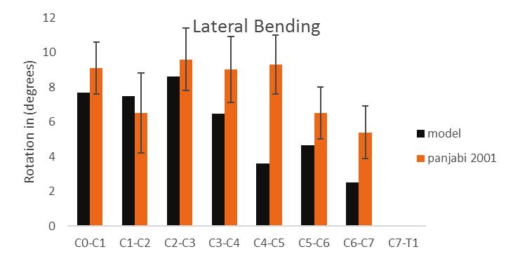
57 5 Validation To validate the created model, the model s static response to a 1 Nˑm. moment was compared to the reported experimental results, as well as other finite element models. The in vitro experiment done by Panjabi et al. (2001), was used to validate the results from the current model. The data were also compared against other finite element models: Palomar et al. (2007); Toosizadeh et al. (2011); Moglo et al. (2012); Zhang et al. (2006); and Han et al. (2012). In the current study, a load of 1 Nˑm. moment was applied in 6 different directions. It was applied at the bottom of the skull, at Atlanto-occipital joint. For the boundary conditions, only the bottom vertebra was restrained from moving or rotating in any direction, the other vertebrae were left free to move or rotate. The rotation at each motion segment was the average between the rotations of the two adjacent vertebrae. 5.1 Experimental data (in vitro) In the experiment that was conducted by Panjabi et al. (2001), the samples were fixed at the bottom from moving or rotating. The external load was applied on the upper most vertebra using a pulley that transfers equal and opposite forces into moments as shown in Figure 3.1. The experiment was carried out by applying six moments of a value of 1 Nˑm. each on three different planes on the samples. Two moments were applied on the sagittal plane (flexion and extension), two along the transverse plane (axial rotation; left and right), and two along frontal plane (lateral bending; spine bending to the left and to the right). The following charts compare the data from the model against those recorded in the experiment by Panjabi et al. (2001). In the charts, the rotations in same planes were combined together; extension with flexion, called flexoextension, and the lateral bending and axial rotation charts summate both right and left sides. 48
58 49
59 50
60 51
61 52
62 Figure 5.6. Lateral bending of the current FEA model and other FEA models. Values summate both right and left sides. Comparing the data obtained in the currently created finite element model and the reported results from the other models, it could be concluded that the data are similar in some of the segments of the spine, while it contradicts past results in other areas. For example, the first two motion segments, the results are almost identical to the ones reported by Zhang et al. (2006). However, the rotation in this model is the average for the first segment, but rotates more than others in the second segment. The C2-C3 segment and other segments all experience higher rotations than the other models except for the C4-C5 level, which rotates approximately the same amount. The difference between the obtained results in the herein study and the previous studies comes from the different material properties used as well as symmetrical geometry assumption that was acquired in the earlier mentioned papers. 53
63 6 Model detailed Output When the spine rotates, the ligaments stretch to limit movement and prevent injury. Different ligaments are distributed all around the vertebrae, on the anterior and posterior surfaces, the sides, and in-between the vertebrae. All the ligaments play a role in limiting the rotation and movement of the vertebrae, however, some of them contribute more to resisting certain loads due to their location. For example, anterior ligaments bear most of the stress in extension rotation, while posterior ligaments limit most of the flexion rotation of the spine. Figure 6.1 shows a theoretical longitudinal transection of the vertebrae and ligaments into anterior and posterior parts. Anterior ligaments are mostly active in extension while posterior ligaments are active in flexion rotation. Figure 6.1. Transection of the ligaments into anterior and posterior sections in flexoextension rotation. (Panjabi, M. 1978). Used with permission. 54
, intertransverse ligament (ISL), annulus fibrosus; both anterior and posterior halves (AHA and PHA), and posterior longitudinal")
64 In Figure 6.1, the anterior ligaments are anterior longitudinal ligament (ALL), intertransverse ligament (ISL), annulus fibrosus; both anterior and posterior halves (AHA and PHA), and posterior longitudinal ligament (PLL). The posterior ligaments are ligamentum flavum (LF), interspinous ligament and nuchal ligament (ISL), facet joint capsule (FJC), as well as facet joints, all contribute to limiting the movement. For lateral bending, the spine sways left and right based on the applied load. When the spine rotates to one side, the ligaments of the opposite side stretch, limiting the movement, and making all the ligaments on the opposite sides active. In this case, the spine is split symmetrically in the middle through the sagittal plane as shown in the following Figure 6.2. Axial rotation is resisted by all the ligaments activated at the same rate whether the spine is rotated in either direction. In the following section, the stress development along each ligament will be presented in all six different rotations. In the following sections, the development of Von Misses stress is presented in the upper cervical spine ligaments Figure 6.2. Transection of the spine into two symmetrical halves. From Which X-Ray Views Should Be Obtained?, 2015, Copyright
65 6.1 Ligaments Flexo-extension When the spine rotates anteriorly in the sagittal plane, it is called flexion, and when it rotates backwards or posteriorly in the sagittal plane, it is called extension. For either of these two rotations, there are certain ligaments that play critical roles in limiting the movement. Applying a moment of a value of 1 Nˑm developed stress in the ligaments as they were trying to limit the movement, and the stress values ranged based on the applied moment, and their position on the spine. The data from this work presents the stress in all of the ligaments in the cervical spine region. The following graphs show the top three motion sections, all other graphs can be found in the appendices. The anterior longitudinal ligament (ALL) is located on the anterior surface of the vertebral body. As the spine rotates in extension, the ligament stretches and thus develops stress, while in flexion it does not have any contribution and buckles, and very small stresses develop in the ligament at the connection point with the vertebra. Figure 6.3 shows the stress development in the ALL at top three motion segments. From Figure 6.3, it can be noticed that ALL is very active in extension rotation, while it has almost no contribution to resisting flexion moment. The highest detectable stress is at the C1-C2 level, then C0-C1 and C2-C3 respectively. The stress in the ALL decreases as going down the spine until it approaches zero at the C7-T1 junction. Some stress is detected in the flexion rotation and that is due to the distal and proximal translation of the vertebrae. 56
66 57
67 The next ligament to be investigated is the posterior longitudinal ligament (PLL). From Figure 6.1, it is located on the posterior surface of the vertebral body, near the longitudinal line that transects vertebrae into posterior and anterior sections. Theoretically, it helps in resisting both flexion and extension moment but it is more predominant in flexion. Figure 6.5 shows the stress on PLL in flexo-extension rotations. Figure 6.5. Stress distribution along PLL. Negative moment is extension while positive moment is flexion. From Figure 6.5, PLL helps in limiting the flexion rotation while it barely has any contribution in limiting the extension rotation, even though it lies in the anterior section of the vertebra. The highest stress is in Atlanto-occipital motion segment (C0-C1) where the stress reaches up to 0.8 MPa, and this is because the skull (C0) has the highest rotation when compared to the rest vertebrae. The reported stress in PLL drops significantly, and the inferior motion segments, as shown in Figure 6.5. The C2-C3 and C3-C4 segments behave similarly in both flexion and extension, although C3-C4 experiences slightly higher stress in flexion. Capsular ligament (CL) is located around the facet joint on the superior and inferior surfaces of a vertebra. Based on Figure 6.1, it lies on the line that transects the vertebra into two halves. Theoretically, it is involved in limiting both flexion, and extension rotations. As anticipated, the CL is active in both flexion and extension. The most stress is developed in C1-C2 segment with being more involved in flexion resisting. C0-C segment is more contributing to the extension resisting than being involved in flexion resisting. C2-C3 is opposite to C0-C1 segment as being more active in flexion as the stress in this region exceeds C0-C1 while it is much less involved in resisting extension. The stress level drops as moving down the spine as it can be seen from the graphs in the appendix. 58
68 Figure 6.6. Stress distribution along CL. Negative moment is extension while positive moment is flexion. Ligamentum flavum (LV) also is located in the posterior region on the vertebra, within a close distance from the longitudinal transection line. Based on its location, LV is mostly active in limiting flexion rotation. The following Figure 6.7 shows the stress distribution along each ligament on C1 through C4 levels. Figure 6.7. Stress distribution along LV. Negative moment is extension while positive moment is flexion. Similar to PLL, LV is mainly active in resisting flexion and has a minimal assistance in resisting extension moment. Similar to ALL and PLL, superior ligaments are more involved than the inferior ones as upper vertebrae rotate more than the bottom vertebrae. However, comparing to 59
69 PLL, LV is not highly involved in resisting flexo-extension rotations although it is more active in flexion than extension. The highest stress value in flexion is about 0.22 MPa whereas 0.8 MPa for PPL, and its contribution decreases as moving down the spinal column. Interspinous ligament (ISL) is located at the posterior margin of the vertebrae connecting two adjacent spinous processes together. Because of its location, ISL is only involved in flexion and has no contribution to extension. Figure 6.8 shows the stress distribution on ISL in both flexion and extension rotations on the top three levels. As the spine rotates in flexion, ISL stretches as trying to hold the vertebrae in position and limiting the movement. This imposes a high stress on the ligament as it can be noticed in Figure 6.8. A stress of a value of 0.3 MPa can be noticed on the superior ligament C1-C2 and it deteriorates as moving to lower levels until the model detects almost a zero stress at the bottom segment C7-T1. C2-C3 and C3-C4 segments respond similarly to the moment in flexion as the stress in these two ligaments is about 0.08 MPa in flexion. In extension, all three ligaments have the same response as very small stress is detected in the ligaments. Figure 6.8. Stress distribution along ITL. Negative moment is extension while positive moment is flexion. At the tip of the spinous processes where the two laminae join, a thin and long ligament joins each two adjacent vertebrae and it is called supraspinous ligament (SSL). It extends all the way from occipital bone down to T1 vertebra. Similar to ITL, it is stretched in flexion as shown in the following graphs. 60
70 Figure 6.9. Stress distribution along SSL. Negative moment is extension while positive moment is flexion. From Figure 6.9, SSL on level C1-C2 stretches the most and thus developing the highest stress comparing to the rest SSL on the other levels. The stress on SSL at C0-C1 is lower than C1-C2 level because in flexion rotation, the ligaments are the only organs holding C1 to C2 as there is no intervertebral disc between the two vertebrae. Thus, high stress is applied on the ligaments inbetween atlas and axis as trying to keep them connected. Being on the posterior section of the spine, it is only active in flexion rotation and does not involve in resisting extension rotation as it was anticipated. Three more ligaments that are only exists in the cervical region that also have contribution in resisting flexion and extension rotations. Alar ligament secures odontoid in position by tying it to lower portion of the occipital bone. It is mainly active flexion as well as axial rotation. Another ligament plays a critical role in holding the odontoid in position and that is transverse ligament. This ligament stretches from one side of atlas on the inner surface to the other side passing odontoid from behind. Similar to alar ligament, it helps keeping Odontoid in position when the spine rotates in flexion. One more ligament also holds Odontoid in position and that is apical ligament. It is attached to the Odontoid from top and it extends upward to the occipital bone. It helps in keeping Odontoid in position. Any movement of Odontoid stretches Apical ligament, and thus stress is developed in the ligament. The following Figure 6.10 shows the stress distribution along the three ligament in flexo-extension rotation. 61
71 Figure Stress distribution along Alar ligament, Transverse ligament and Apcai ligament. Negative moment is extension while positive moment is flexion. When the spine goes in extension, the back face of the anterior arch pushes on Odontoid and thus Alar ligament experiences a tensile stress. On the other hand, when the spine goes on flexion rotation, Atlas pulls on Alar ligament and in turn, it pulls on Odontoid. This stretching puts a high stress on Alar ligament as it can be noticed from Figure The stress continues rising as the applied moment increases. From the previous Figure 6.10, the stress on transverse ligament is relatively higher in flexion comparing it to the extension. In extension rotation, there is a sudden increase at the beginning but it decreases as the load increases and that is due to the proximaldistal transition effect on the model. However, in flexion, it keeps rising as the applied moment increases. Comparing transverse ligament to Alar ligament, Alar ligament experiences higher stress in flexion, almost twice the stress comparing to transverse ligament and this is indicates the critical role in keeping Odontoid in position during flexion rotation. Also from Figure 6.10, it can be concluded that Apical ligament is very active in resisting flexion rotation while a minimal contribution in extension rotation. In flexion, it starts with a small peak and then drops down to zero. But, then the stress picks up going up to 0.5 MPa at 1 Nˑm moment. In extension, similarly to flexion there is a small peak and then the stress decreased to zero. A small stress develops in the ligament as a higher moment is applied but it is very small comparing to the stress in flexion rotation. 62
72 63
73 64
74 Figure Stress distribution along PLL. Negative moment indicates rotation to the left side while positive indicates right side rotation. Similar to ALL and ITL, the C0-C1 segment has experienced the highest stress compared to the lower segments as it reaches 0.6 MPa in the positive rotation. Unsymmetrical behaviour is noticed as the negative rotation stress is about half of the positive rotation as that is because of the irregular geometry of the model. Stress level drops significantly in the lower segments as it can be seen in Figure Capsular ligament (CL) is a circular ligament that surrounds facet joint. When the model goes under axial rotation, CL experiences torsional effect. With that, some area experience relatively high stress and some other area very low stress. The following Figure 6.14 shows the stress along CL. Figure Stress distribution along PLL. Negative moment indicates rotation to the left side while positive indicates right side rotation. 65
75 The highest rotation degree in axial rotation is at C1-C2 segment and that reflects the amount of stress in the ligaments in that segment experience. The highest stress in CL is in the C1-C2 region due to high rotation in that region, followed up by C0-C1 segment in the negative rotation (spine rotating to the left) while C2-C3 has higher stress rotating in the other direction (positive rotation). Although C1-C2 has unsymmetrical response, but the stress values at 1 Nˑm moment are similar. LV runs along the laminae process to the joining point. LV is a broad ligament that holds two adjacent vertebrae together. The following Figure 6.15 shows the stress along LV for the applied 1 Nˑm. Figure Stress distribution along PLL. Negative moment indicates rotation to the left side while positive indicates right side rotation. When the spine rotates, LV has a minimal contribution in resisting the applied moment comparing to ALL, ITL, PLL and CL. Similar to the previously mentioned ligaments, C1-C2 has the highest resistance due to the rotational degree of the spine. The lower ligaments experience very low stress as the stress decreased to zero at the very bottom motion segment. C2-C3 and C3-C4 segment have symmetrical behaviour on both sides unlike the very top ligament where behaviour and stress are distinct on both sides. ISL connects the spinous process of two adjacent vertebrae together. When the spine goes in axial rotation, ISL experiences tension and rotational stresses. Figure 6.16 shows the stress distribution along the ligament. 66
76 Figure Stress distribution along ISL. Negative moment indicates rotation to the left side while positive indicates right side rotation. The stress in ITL is different at each level. C1-C2 is more active in positive rotation than negative rotation. In the positive direction, the stress in C1-C2 is the highest as it is MPa while it is the lowest among the top three in the negative direction.c2-c3 segment has a symmetrical response in both axial rotations. The stress in this segment is lowest in positive direction and it is a little higher in the negative direction. Just like the most top segment, the stress C3-C4 is asymmetric as the stress is highest in the negative direction while the stress is lower than C1-C2 segment in the positive direction. Along with ISL, there is SSL that joins the tip of spinous process together. They are thin long ligaments that run from the skull (C0) down to T1 vertebra. In axial rotation, it develops torsional effect and goes under tension stress in some areas. Figure 6.17 shows the stress along the ligament. From Figure 6.17, it can be noticed that SSL did not get significantly affected by the applied rotational moment on the spine. C1-C2 segment has the highest stress in positive rotation. While in negative rotation, the top three segments have the same stress at 1 Nˑm C0-C1 and C2-C3 have the symmetrical response to the applied moment. However, C1-C2 segment has distinct response to either moment as shown in Figure
77 68
78 6.1.3 Lateral Bending Another test was performed on the spine and that was lateral bending on both directions. 1 Nˑm moment was applied on both directions making the spine rotate in frontal plane. When the spine rotates in either direction, ligaments tend to limit the movement and thus develop stress. Figure 6.2 divides spine into two halves; when the spine rotates to the right, the ligaments on the opposite side are stretched and tend to resist the moment and vice versa. In Figure 6.2, ALL is divided into two equal halves; each half is stretched in each direction. When the spine rotates to the left, the right portion of ALL is activated in order to resist the rotation and when the spine rotates to right, the left portion is activated and develops stress. Figure Stress distribution along ALL. Negative moment indicates the spine rotates to the left side while positive indicates the right side rotation. From Figure 6.19, C0-C1 motion segment is barely involved in resisting the lateral bending. That is due to the fact that the skull (C0) and Atlas stick together and act as one unit when the spine rotates in lateral bending. On the other hand, C1-C2 segment has the highest stress. It starts with a peak due to proximal-distal translation and then the stress decreases as the load is increasing and the spine starts to rotate. C2-C3 segment also has a relatively small stress and it behaves unsymmetrically. The rest of the ligaments experience low stress comparing to C1-C2 segment. 69
79 70
80 71
81 72
82 73
83 74
84 6.2 Facet Joint Another component that plays a major role in limiting the spine movement is called facet joint. Facet joints are extensions from pedicle and lamina connection. Each vertebra has four facet joints, two on the superior surface and two on the posterior surface. As the spine rotates, facets on the superior surface push against the facet joints on the inferior surface of the superior vertebra, this provides stability for the spine as well as resisting and limiting movement of the spine. The contact force presented here is the magnitude of all the force components in each direction Flexo-extension Facet joints play a critical role in resisting flexo-extension rotation. When the spine rotates in flexion, the facet joint surfaces move away from each other except for the top two joints where they still push onto each other. For Atlanto-occipital joint, the condyle of occipital bone glides against the posterior wall of the concave atlantal facet. For Atlanto-axial joint arthrokinemtic, the facet joins on the two vertebrae glide on each other in all direction movement. The following Figure 6.27 shows the contact force between facet joints at different levels for flexion and extension rotations. Figure Contact force between facet joints at all levels of cervical spine in flexoextension rotation. When the spine rotates in flexion, every couple facet joint move apart from each other, except for Atlanto-occipital and Atlanto-axial joints. From Figure 6.27, the contact force on the upper most joint is about 20 N while it is higher at the C1-C2 segment and it is about 50 N. the contact force among the other joints is zero expect for the C5-C6 segment which indicates a contact happening between the facet joints and the reported contact force is about 45 N. 75
85 In extension rotation, as the spine moves backwards, the facet joins come in contact and start pushing onto each other. From the previous Figure 6.27, facet joints at all levels are in contact except for the C4-C5 segment. As the spine move in extension, the contact force at C0-C1 segment is higher than it is in flexion because in flexion, ligaments are more engaged in limiting the rotation while in extension, the spine mainly relies on the facet joins to limit the movement and to transfer the loads Axial Rotation As the spine rotates to the left or right, one of the two pairs of the facet joint is being active. On each level, there is a pair of facet joint and when the spine goes through axial rotation, one joint is getting involved in limiting the movement while the other is having the facets moving apart from each other. 76
86 77
87 the applied force as the ligaments are more involved in one side than the other side. Also, it can be noticed that the facet joint at the top two levels are always active whether the spine is rotating to the left or right. Also, segment C4-C5 detects no contact force at its facet joint. The imperfection of the model resulted in a no force facet joint at C4-C5 segment due to the gap between the facet surfaces Lateral Bending Similar to the axial rotation when the spine sways to either direction, one side of the facet joints are active as the facet joints surfaces get closer and push on each other, while every facet joint couple on the other side is moving away from each other. When they come in contact, the facet joint exerts pressure on each other. The following Figure 6.29 shows the contact force among the facet joint in lateral bending. 78
88 79
89 80
90 Figure Total force in the annulus fibrosus at each levels. Intervertebral disc has different response to the applied flexo-extension moment. From Figure 6.30, the pressure at C2-C3 nucleus in flexion is higher than it is in extension, indicating its contribution in resisting flexion is higher than resisting extension. C3-C4 and C4-C5 segments behave in the same manner. The tensile force in annulus fibrous reflects the pressure in nucleus. The highest force is C2-C3 segment which is in agreement with the highest pressure which is also in the C2-C3 segment. C3-C4 segment has the highest force then C4-C5 segment. High stress on intervertebral disc generates high pressure on nucleus pushing it against the annulus pulposus and thus high force in annulus fibrousus Axial Rotation As the spine goes in axial rotation, the rotational movement of the spine exerts stress on the intervertebral disc. As the spine rotates, nucleus goes under pressure and in turn, it pushes against the annulus. This process generates force in annulus fibrous making it extend. The following Figure 6.32 shows the pressure in nucleus as well as force in the annulus fibrosus. 81
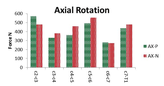
91 82
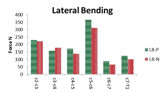
92 83
93 in the fibres indicate that higher force in the left side rotation. Pressure level and fibrosus force at C3-C4 segment in the fibers are in agreement as pressure on right side rotation is higher than the left side rotation and the force in the right side rotation is higher than the other side. C4-C5 segment is similar to C2-C3 segment in terms of the pressure level as well as the force in the fibers; pressure on nucleus is higher on the right side rotation but the force is higher on the left side rotation. Some imperfections come from the fixed surfaces of the vertebrae; the areas that had to be reconstructed due to surface interference. 84
94 7 Discussion and Recommendation In the herein study, a three-dimensional complete ligamentous cervical spine had been used to assess and anticipate the stress distribution along the ligaments. The created numerical model consisted of skull, vertebrae (C1-T1), intervertebral disc, and bio-realistic geometry and refined mesh of ligament that would distinguish it from the previously published models Palomar et al. (2007); Moglo et al. (2012); N. Toosizadeh et al. (2011); and Zhang et al. (2006). The created ligaments would enable to simulate the contour plot of the stress on the ligaments as well as to anticipate the high stress initiation point and propagation path. Using the current model, stress initiation and distribution was possible along the ligaments. In vitro studies, experiments presented the range of motion of the cervical spine under six rotational moments: flextion, extension, axial rotation in positive and negative directions as well as lateral bending in positive and negative direction. However, it failed to report the stress in the ligaments due to lacking the lab instruments that would measure the stress. For the numerical studies mentioned earlier, the used elements to represent ligaments would only output axial force and strain in the ligaments. Validation of the range of motion of the current model was done by comparing with the in vitro experiments carried by Panjabi et al. (2001). The model was fixed at the bottom level (T1), while the spine was left unrestrained at the top. A moment of a value of 1 Nˑm. was applied on three different planes; two moments along sagittal plane, two along the transverse plane and the other two along the frontal plane. The load was applied on the most top component (C0). The obtained response from the current model was in agreement with the reported range of motion from the in-vitro experiment as well as the other finite element models. This indicates that the current model can provide relevant information regarding the cervical spine behaviour under any given static load. The created model anticipated that the upper cervical spine (C0-C2) rotates more than the lower part of the spine. The rotation at this section is about half or higher of the total rotation of the cervical spine as shown in Figure 5.1 through Figure 5.3. This flexibility is a result of anatomic characteristics of the C0-C2 joints. In these segments, there is no intervertebral existing in 85

95 between the motion segments, but they are joined by ligaments only. A small load on the spine made the upper cervical spine go under large rotations due to the initial low stiffness of the ligaments. This makes ligaments in these regions vulnerable to high stresses comparing to the ligaments in the other segments. In flexo-extension rotation, the highest stress in all ligaments was reported in the upper regions. In flexion, the applied moment was carried by intervertebral disc resulting in compression in the anterior part of the disc. With simultaneous contribution from the ligaments, flexion rotation resulted in tensile stress in the posterior ligaments of the spine. As ligaments being stretched, tensile stress was initiated. Depending on the ligaments orientation with respect to the applied moment, high stress area concentrated on different areas on the ligament. In flexo-extension, stress was concentrated in the center region of the ligaments as shown in Figure 7.1. The stress initiated in the center region and propagated to the other regions on the ligament. ISL was the only ligament that had stress being concentrated on different area on the ligament. As being on the posterior part of the spine, ISL was only stretched in flexion and the stress was on the inferior poster corner of the ligament. Figure 7.2 shows high stress area in ISL. Figure 7.1. High stress region in ligamentum flavum in flexion rotation at 1 NˑM 86

96 Figure 7.2. High stress region in supraspinous ligament in flexion rotation at 1 NˑM About 70 percent of the total load in flexion is carried by ligaments while 4 percent by the intervertebral disc and 26 percent by the facet joints. Out of that 70 percent, 40 percent is concentrated in the upper cervical spine with 17 percent in C0-C1 segment and 23 percent in C1- C2 segment. The stress in this region reflects the high rotation in the upper cervical spine. The remaining 60 percent of the stress in ligaments is distributed accordingly in each segment based on the rotation at each level. The range of motion was smaller as moving down the spine and so did the stress at each level. Minimal stress in the lower spinal section emphasise the significance of intervertebral disc s role in resisting external load. In the upper cervical spine, the highest stress was in the posterior longitudinal ligament with 54 percent of the total stress in the C0-C1 segment. However, in C1-C2 segment, capsular ligament experienced the highest stress with 60 percent of the total stress in the segment. In the lower cervical spine, capsular ligament experienced the most of the tensile stress as the spine went in flexion. The stress on the intervertebral disc correlated to the range of motion in the spine. C2-C3 has the highest rotation and thus stress in the disc was the highest comparing to the lower levels with 31 percent of the total stress in the disc. The stress on the disc drops in the lower with smaller rotation in the region. The 26 percent stress on facet joint was based mainly on the upper cervical spine due to anatomic geometry of the top two segments. 20 percent of the stress in facet joint was concentrated in C0-C1 segment while 48 percent in the C1-C2 segment. A minimal stress was detected in the lower regions except in C5-C6 segment with 32 percent of total stress in the facet joint. 87

97 In extension, unlike flexion, most of the load was carried by the facet joints, which was reflected on the stress level at the facet joint with 62 percent of the total stress. 36 percent of the total stress was in the ligaments and 2 percent in the intervertebral disc. The highest stress on facet joints was reported at the C5-C6 segment with 33 percent indicating that it is a fluctuation point on the spine in extension. Segments below C5-C6 have small rotations while upper segments go through rotation. The stress in the facet joint in the upper cervical spine (C0-C2) makes 40 percent of the total stress on the facet joints with about 20 percent at each level. With high stress on facet joints, intervertebral discs experience a small pressure from vertebral bodies as small portion of the extension moment was transferred to the intervertebral discs. The vast majority of the total stress was concentrated in anterior longitudinal ligament during extension, while the disc is being compressed on the posterior part and only anterior ligaments being engaged in limiting the rotation. 54 percent of the total stress in the ligaments was at the C0-C2 segments with about 28 percent at each level. Out of 28 percent of the stress in the ligaments, 58 percent was concentrated at ALL and 35 percent at the capsular ligament. This indicates that high rotation in the upper cervical spine comes with the cost of having high stress in the ligaments. In axial rotation, the three components of the cervical spine collaborate together in resisting the load in both directions. As the loading starts on the spine, stress start developing in the ligaments immediately. In the ligaments, the stress was noticed to have a diagonal pattern with high stress levels at the corners of which the ligaments is being pulled by. While the low stress areas are at the other two corners. The following Figure 7.3 shows the high stress areas in ALL in axial rotation. Figure 7.3. Front view of high stress region in ALL in positive axial rotation at 1 NˑM 88
98 The facet joint and ligaments share the stress coming from the applied load with 45 percent in the ligaments and 48 percent in the facet joint while the intervertebral disc experiences 7 percent. The highest rotation angle was noticed at the C1-C2 segment, which was associated with highest stress in the ligaments with 22 percent of the total stress in the ligaments. The second highest stress in the ligaments was at C0-C1 segment, which also happened to be the second highest rotation detected in the spine. This indicated the association of the high stress with the high rotation in the spine. Capsular ligament had the highest stress with an average of 75 percent at each segments. In the most top segment (C0-C1), it carried about 40 percent of the total stress in the section, while it reached 87 percent in the C1-C2 segment. The second most ligaments contributing in resisting the load were ALL and PLL with an average of 8 percent each. ALL and PLL had the highest stress in the C0-C1 segment with 32 and 23 percent respectively of the total stress in the section. Their role was minimal in the lower regions as most of the stress was concentrated at capsular ligaments. Other ligaments also had stress developed in them, however it was nominal comparing to capsular ligament. This observation indicates that in axial rotation, most of the stresses were carried by CL and it shows essentialness of CL in limiting axial rotation. For facet joint, most of the stress was concentrated at the C5-C6 segment with about 50 percent of the total stresses in the facet joints. Here again, C5-C6 segment acting as fluctuation point between the upper part (C0-C5) and lower part (C6-T1). The upper segments are more mobile and thus they are more flexible and responsive to an applied load while lower segments are stiffer. The second highest stress was at the C1-C2 segment which also happens to have the highest rotation. The third highest stress was C0-C1 segment. This also proves that the upper cervical spine (C0-C2) is more flexible than the rest of the spine. Just like facet joints, the highest compressive stress on the intervertebral disc was at the C5-C6 segment and that is due translation from flexible part of the spine (C0-C5) to the stiffer part (C6- T1). 42 percent of the total stress in disc was at this level. 36 percent was in the upper level and 20 in the C6-T1 sections. In lateral bending, the spine rotates to the left and to the right accordingly. Two things were taken from this movement; one of them is that the ligaments on one side undergo tensile stress and thus stretches and the second thing is that ligaments in the middle of the spine are divided 89

99 into two halves, one half getting stretched while the other half being lax. For instance, anterior longitudinal ligament is located in the middle region of the spine, when lateral load was applied, it was half stretched as seen in the following Figure 7.4. Another noticeable takeout from this test was that C0-C1 segment was acting as one unit. From the previous cases, it was clear the influence of facet joint in transferring the load to the lower levels, but in lateral bending, there was merely any stress developed in the joint indicating that this segment was acting as one unit held together by ligaments. Figure 7.4. Front view of high stress region in ALL in positive lateral bending at 1 NˑM The stress distribution among ligaments and fact joints was equal with 48 percent each and 4 percent carried by the intervertebral disc. The highest stress value was at the C0-C1 segment and it was all concentrated in the ligaments as they held up C0 and C1 together. Most of the stress was shared between CL and ITL with 96 percent and 4 percent in each respectively. Ligaments in C1-C2 segment had 34 percent of the total stress in the segment with most of it being in CL as well. C4-C5 segment has the second highest stress with 89 percent of the total stress in the segment. The rest of the stress was developed in the intervertebral disc and no stress was detected at the facet joints. CL along with ITL shared most of the stress with 60 percent in the Cl and 33 percent in ITL. The value of the stress fluctuates with the rotation angles in each segment as it varies moving down the spine. The facet joint played a major role in stabilizing the supporting the spine in lateral bending. 46 percent of the total stress on the spine was shared by facet joint. Similar to the ligaments, the stress values ranged in each segment based on the rotation at each level. Analogous to the axial rotation and flexo-extension rotations, C5-C6 segment facet joint experienced the highest stress in the cervical spine. The stress in the discs was minimal as only 3 of the total stress was carried 90
VERTEBRAL COLUMN VERTEBRAL COLUMN
 VERTEBRAL COLUMN FUNCTIONS: 1) Support weight - transmits weight to pelvis and lower limbs 2) Houses and protects spinal cord - spinal nerves leave cord between vertebrae 3) Permits movements - *clinical
2. The vertebral arch is composed of pedicles (projecting from the body) and laminae (uniting arch posteriorly).
 and laminae (uniting arch posteriorly).") VERTEBRAL COLUMN 2018zillmusom I. VERTEBRAL COLUMN - functions to support weight of body and protect spinal cord while permitting movements of trunk and providing for muscle attachments. A. Typical vertebra
VERTEBRAL COLUMN 2018zillmusom I. VERTEBRAL COLUMN - functions to support weight of body and protect spinal cord while permitting movements of trunk and providing for muscle attachments. A. Typical vertebra
THE VERTEBRAL COLUMN. Average adult length: In male: about 70 cms. In female: about 65 cms.
 THE VERTEBRAL COLUMN Average adult length: In male: about 70 cms. In female: about 65 cms. 1 Vertebral Column (Regions and Curvatures) Curvatures of the vertebral column: A. Primary curvature: C-shaped;
Copyright 2010 Pearson Education, Inc. Copyright 2010 Pearson Education, Inc. Figure Sectioned spinous process. Interspinous.
 PowerPoint Lecture Slides prepared by Janice Meeking, Mount Royal College C H A P T E R 7 The Skeleton: Part B Vertebral Column Transmits weight of trunk to lower limbs Surrounds and protects spinal cord
Clarification of Terms
 Clarification of Terms The Spine, Spinal Column, and Vertebral Column are synonymous terms referring to the bony components housing the spinal cord Spinal Cord = made of nervous tissue Facet = a small,
Clarification of Terms
 Clarification of Terms The Spine, Spinal Column, and Vertebral Column are synonymous terms referring to the bony components housing the spinal cord Spinal Cord = made of nervous tissue Facet = a small,
human anatomy 2015 lecture four Dr meethak ali ahmed neurosurgeon
 The Vertebral Column the vertebral columnis central pillar of the body.it serve to protect the spinal cord and support the weight of the head trunk, which it transmits to the hip bones & the lower limbs.
Clarification of Terms
 Clarification of Terms The Spine, Spinal Column, and Vertebral Column are synonymous terms referring to the bony components housing the spinal cord Spinal Cord = made of nervous tissue Facet = a small,
Cervical Spine Anatomy and Biomechanics. Typical Cervical Vertebra C3 6. Typical Cervical Vertebra Anterior 10/5/2017
 Cervical Spine Anatomy and Biomechanics Typical Cervical Vertebra C3 6 Small, relatively broad body Bifid SpinousProcess Long and narrow laminae Spinal Canal: large, triangular; remarkably consistent dimensions
Ligaments of the vertebral column:
 In the last lecture we started talking about the joints in the vertebral column, and we said that there are two types of joints between adjacent vertebrae: 1. Between the bodies of the vertebrae; which
AXIAL SKELETON FORM THE VERTICAL AXIS OF THE BODY CONSISTS OF 80 BONES INCLUDES BONES OF HEAD, VERTEBRAL COLUMN, RIBS,STERNUM
 AXIAL SKELETON FORM THE VERTICAL AXIS OF THE BODY CONSISTS OF 80 BONES INCLUDES BONES OF HEAD, VERTEBRAL COLUMN, RIBS,STERNUM APPENDICULAR SKELETON BONES OF THE FREE APPENDAGES & THEIR POINTS OF ATTACHMENTS
Copyright 2010 Pearson Education, Inc.
 E. VERTEBRAL COLUMN 1. The vertebral column extends from the skull to the pelvis and forms the vertical axis of the skeleton. 2. The vertebral column is composed of vertebrae that are separated by intervertebral
It consist of two components: the outer, laminar fibrous container (or annulus), and the inner, semifluid mass (the nucleus pulposus).
, and the inner, semifluid mass (the nucleus pulposus).") Lumbar Spine The lumbar vertebrae are the last five vertebrae of the vertebral column. They are particularly large and heavy when compared with the vertebrae of the cervical or thoracicc spine. Their bodies
Lumbar Spine The lumbar vertebrae are the last five vertebrae of the vertebral column. They are particularly large and heavy when compared with the vertebrae of the cervical or thoracicc spine. Their bodies
Dr Ajit Singh Moderator Dr P S Chandra Dr Rajender Kumar
 BIOMECHANICS OF SPINE Dr Ajit Singh Moderator Dr P S Chandra Dr Rajender Kumar What is biomechanics? Biomechanics is the study of the consequences of application of external force on the spine Primary
The vault bones Frontal Parietals Occiput Temporals Sphenoid Ethmoid
 The Vertebral Column Head, Neck and Spine Bones of the head Some consider the bones of the head in terms of the vault bones and the facial bones hanging off the front of them The vault bones Frontal Parietals
Axial Skeleton: Vertebrae and Thorax
 Axial Skeleton: Vertebrae and Thorax Function of the vertebral column (spine or backbone): 1) 2) 3) Composition of Vertebral column The vertebral column is formed by 33 individual vertebrae (some of which
Bony framework of the vertebral column Structure of the vertebral column
 5.1: Vertebral column & back. Overview. Bones o vertebral column. o typical vertebra. o vertebral canal. o spinal nerves. Joints o Intervertebral disc. o Zygapophyseal (facet) joint. Muscles o 2 compartments:
Chapter 7 Part B The Skeleton
 Chapter 7 Part B The Skeleton 7.2 The Vertebral Column General Characteristics Extends from skull to pelvis Also called spine or spinal column Functions to transmit weight of trunk to lower limbs, surround
River North Pain Management Consultants, S.C., Axel Vargas, M.D., Regional Anesthesiology and Interventional Pain Management.
 River North Pain Management Consultants, S.C., Axel Vargas, M.D., Regional Anesthesiology and Interventional Pain Management. Chicago, Illinois, 60611 Phone: (888) 951-6471 Fax: (888) 961-6471 Clinical
THE THORACIC WALL. Boundaries Posteriorly by the thoracic part of the vertebral column. Anteriorly by the sternum and costal cartilages
 THE THORACIC WALL Boundaries Posteriorly by the thoracic part of the vertebral column Anteriorly by the sternum and costal cartilages Laterally by the ribs and intercostal spaces Superiorly by the suprapleural
Vertebral Column. Backbone consists of 26 vertebrae. Five vertebral regions. Cervical
 Vertebral Column Backbone consists of 26 vertebrae. Five vertebral regions Cervical vertebrae (7) in the neck. Thoracic vertebrae (12) in the thorax. Lumbar vertebrae (5) in the lower back. Sacrum (5,
Skeletal System. Axial Division
 Skeletal System Axial Division The Axial Skeleton You will see that each bone has special features (overviewed in section I below) that provide Sites of Attachment (for muscles, ligaments, tendons, etc.)
INDEPENDENT LEARNING: DISC HERNIATION IN THE NATIONAL FOOTBALL LEAGUE: ANATOMICAL FACTORS TO CONSIDER IN REVIEW
 INDEPENDENT LEARNING: DISC HERNIATION IN THE NATIONAL FOOTBALL LEAGUE: ANATOMICAL FACTORS TO CONSIDER IN REVIEW CDC REPORT - CAUSES OF DISABILITY, 2005 REVIEW QUESTIONS ABOUT DISC HERNIATION IN THE NATIONAL
Main Menu. Trunk and Spinal Column click here. The Power is in Your Hands
 1 The Trunk and Spinal Column click here Main Menu K.9 http://www.handsonlineeducation.com/classes/k9/k9entry.htm[3/27/18, 2:00:55 PM] The Trunk and Spinal Column Vertebral column complex 24 intricate
THEME 2. VERTEBRAE (GENERAL DATA). CERVICAL, THORACIC AND LUMBAR VERTEBRAE. SACRUM. COCCYX. THE VERTEBRAL COLUMN AS A WHOLE
. CERVICAL, THORACIC AND LUMBAR VERTEBRAE. SACRUM. COCCYX. THE VERTEBRAL COLUMN AS A WHOLE") THEME 2. VERTEBRAE (GENERAL DATA). CERVICAL, THORACIC AND LUMBAR VERTEBRAE. SACRUM. COCCYX. THE VERTEBRAL COLUMN AS A WHOLE Osteology of the Vertebral Column Bone Description vertebra Notes a vertebra
THEME 2. VERTEBRAE (GENERAL DATA). CERVICAL, THORACIC AND LUMBAR VERTEBRAE. SACRUM. COCCYX. THE VERTEBRAL COLUMN AS A WHOLE Osteology of the Vertebral Column Bone Description vertebra Notes a vertebra
The Biomechanics of the Human Spine. Basic Biomechanics, 6 th edition By Susan J. Hall, Ph.D.
 Chapter 9 The Biomechanics of the Human Spine Structure of the Spine The spine is a curved stack of 33 vertebrae structurally divided into five regions: cervical region - 7 vertebrae thoracic region -
Anatomy of the Spine. Figure 1. (left) The spine has three natural curves that form an S-shape; strong muscles keep our spine in alignment.
 The spine has three natural curves that form an S-shape; strong muscles keep our spine in alignment.") 1 2 Anatomy of the Spine Overview The spine is made of 33 individual bony vertebrae stacked one on top of the other. This spinal column provides the main support for your body, allowing you to stand upright,
1 2 Anatomy of the Spine Overview The spine is made of 33 individual bony vertebrae stacked one on top of the other. This spinal column provides the main support for your body, allowing you to stand upright,
Structure and Function of the Vertebral Column
 Structure and Function of the Vertebral Column Posture Vertebral Alignment Does it really matter? Yes it does! Postural Curves The vertebral column has a series of counterbalancing curves posterior anterior
VERTEBRAL COLUMN ANATOMY IN CNS COURSE
 VERTEBRAL COLUMN ANATOMY IN CNS COURSE Vertebral body Sections of the spine Atlas (C1) Axis (C2) What type of joint is formed between atlas and axis? Pivot joint What name is given to a fracture of both
MD Bones & Joints of the Back. A/Prof Chris Briggs Department of Anatomy & Neuroscience
 MD 2017 Bones & Joints of the Back A/Prof Chris Briggs Department of Anatomy & Neuroscience WARNING This material has been provided to you pursuant to section 49 of the Copyright Act 1968 (the Act) for
Any of the vertebra in the cervical (neck) region of the spinal column. The cervical vertebra are the smallest vertebra in the spine, reflective of th
 region of the spinal column. The cervical vertebra are the smallest vertebra in the spine, reflective of th") Any of the vertebra in the cervical (neck) region of the spinal column. The cervical vertebra are the smallest vertebra in the spine, reflective of the fact that they support the least load. In humans,
Any of the vertebra in the cervical (neck) region of the spinal column. The cervical vertebra are the smallest vertebra in the spine, reflective of the fact that they support the least load. In humans,
Anatomy and Physiology II. Spine
 Anatomy and Physiology II Spine Bones and Other Structures Vertibrae Contains Cervical, Thoracic, Lumbar, Sacral and Coccygeal regions We use Capital letters to refer to these (C, T, L, S, and Co) and
 P R E S E N T S Dr. Mufa T. Ghadiali is skilled in all aspects of General Surgery. His General Surgery Services include: General Surgery Advanced Laparoscopic Surgery Surgical Oncology Gastrointestinal
ANATOMY & PHYSIOLOGY I Laboratory Version B Name Section. REVIEW SHEET Exercise 10 Axial Skeleton
 ANATOMY & PHYSIOLOGY I Laboratory Version B Name Section REVIEW SHEET Exercise 10 Axial Skeleton 1 POINT EACH. THE SKULL MULTIPLE CHOICE 1. The major components of the axial skeleton include the 7. The
Chapter 7. Skeletal System
 Chapter 7 Skeletal System 1 Skull A. The skull is made up of 22 bones: 8 cranial bones, 13 facial bones, and the mandible. B. The Cranium encloses and protects the brain, provides attachments for muscles,
8/4/2012. Causes and Cures. Nucleus pulposus. Annulus fibrosis. Vertebral end plate % water. Deforms under pressure
 Causes and Cures Intervertebral discs Facet (zygopophyseal) joints Inter body joints Spinal nerve roots Nerve compression Pathological conditions Video Causes of back pain Nucleus pulposus Annulus fibrosis
Anatomy. Anatomy deals with the structure of the human body, and includes a precise language on body positions and relationships between body parts.
 Anatomy deals with the structure of the human body, and includes a precise language on body positions and relationships between body parts. Proper instruction on safe and efficient exercise technique requires
Thoracic and Lumbar Spine Anatomy.
 Thoracic and Lumbar Spine Anatomy www.fisiokinesiterapia.biz Thoracic Vertebrae Bodies Pedicles Laminae Spinous Processes Transverse Processes Inferior & Superior Facets Distinguishing Feature Costal Fovea
Arthrology joint, articulation or union between two or more bones Classification by degree of movement or tissue that bind the bones together
 ARTICULATIONS OF THE SPINE AND THORAX Pages 8-12, 42 and 57 Arthrology joint, articulation or union between two or more bones Classification by degree of movement or tissue that bind the bones together
LEARN * DREAM * AWAKEN* DISCOVER * ENLIGHTEN * INVESTIGATE * QUESTION * EXPLORE
 S C I E N C E H U M A N Spine & Vertebrate The Spine & Vertebrate in Focus This Enrichment4You e-guide provides a brief overview of the spine and vertebrate. In this e-guide you will: Human Body Spine/Vertebrate
Yara saddam & Dana Qatawneh. Razi kittaneh. Maher hadidi
 1 Yara saddam & Dana Qatawneh Razi kittaneh Maher hadidi LECTURE 10 THORAX The thorax extends from the root of the neck to the abdomen. The thorax has a Thoracic wall Thoracic cavity and it is divided
You have 24 vertebrae in your spinal column. Two are special enough to be individually named.
 You have 24 vertebrae in your spinal column. Two are special enough to be individually named. Your atlas (C01) and axis (C02) are very important vertebrae. Without them, head and neck movement would be
Overview of the Skeleton: Bone Markings
 Name Overview of the Skeleton: Bone Markings Match the terms in column B with the appropriate description in column A. Column A 1. sharp, slender process* 2. small rounded projection* 3. narrow ridge of
The Back. Anatomy RHS 241 Lecture 9 Dr. Einas Al-Eisa
 The Back Anatomy RHS 241 Lecture 9 Dr. Einas Al-Eisa The spine has to meet 2 functions Strength Mobility Stability of the vertebral column is provided by: Deep intrinsic muscles of the back Ligaments
Module: #15 Lumbar Spine Fusion. Author(s): Jenni Buckley, PhD. Date Created: March 27 th, Last Updated:
: Jenni Buckley, PhD. Date Created: March 27 th, Last Updated:") Module: #15 Lumbar Spine Fusion Author(s): Jenni Buckley, PhD Date Created: March 27 th, 2011 Last Updated: Summary: Students will perform a single level lumbar spine fusion to treat lumbar spinal stenosis.
Module: #15 Lumbar Spine Fusion Author(s): Jenni Buckley, PhD Date Created: March 27 th, 2011 Last Updated: Summary: Students will perform a single level lumbar spine fusion to treat lumbar spinal stenosis.
Chapter 9 Articulations Articulations joints where two bones interconnect. Two classification methods are used to categorize joints:
 Chapter 9 Articulations Articulations joints where two bones interconnect Two classification methods are used to categorize joints: Functional classification Structural classification Functional classification
The Thoracic Cage ANATOMY 2: THORACIC CAGE AND VERTEBRAL COLUMN
 ANATOMY 2: THORACIC CAGE AND VERTEBRAL COLUMN PSK 4U Mr. S. Kelly North Grenville DHS The Thoracic Cage 7 true ribs 3 false ribs 2 floating ribs Clavicle = collarbone Manubrium Sternum Xiphoid Process
Skeletal system. Prof. Abdulameer Al-Nuaimi. E. mail:
 Skeletal system Prof. Abdulameer Al-Nuaimi E-mail: a.al-nuaimi@sheffield.ac.uk E. mail: abdulameerh@yahoo.com Functions of Bone and The Skeletal System Support: The skeleton serves as the structural framework
The Trunk and Spinal Column Kinesiology Cuneyt Mirzanli Istanbul Gelisim University
 The Trunk and Spinal Column Kinesiology Cuneyt Mirzanli Istanbul Gelisim University The Trunk and Spinal Column Vertebral column 24 articulating vertebrae 31 pairs of spinal nerves Abdominal muscles some
Human Anatomy and Physiology - Problem Drill 07: The Skeletal System Axial Skeleton
 Human Anatomy and Physiology - Problem Drill 07: The Skeletal System Axial Skeleton Question No. 1 of 10 Which of the following statements about the axial skeleton is correct? Question #01 A. The axial
Human Anatomy - Problem Drill 06: The Skeletal System Axial Skeleton & Articualtions
 Human Anatomy - Problem Drill 06: The Skeletal System Axial Skeleton & Articualtions Question No. 1 of 10 Instructions: (1) Read the problem and answer choices carefully, (2) Work the problems on paper
Spinal Column. Anatomy Of The Spine
 Anatomy Of The Spine The spine is a flexible column, composed of a stack of individual bones. Each bone is called a vertebra. There are seven vertebrae in the neck (cervical vertebrae) twelve in the thoracic
Chapter 7: Skeletal System: Gross Anatomy
 Chapter 7: Skeletal System: Gross Anatomy I. General Considerations A. How many bones in an average adult skeleton? B. Anatomic features of bones are based on II. Axial Skeleton A. Skull 1. Functionally
Anatomy Lecture #19 AN INTRODUCTION TO THE THORAX April 3, 2012
 Page 1 بسم الله الرحمن الرحيم The Thoracic Wall Firstly, when we talk about thorax, we should begin with the thorax wall which means not only bones that construct the thorax but also the muscles which
o Diaphysis o Area where red marrow is found o Area where yellow marrow is found o Epiphyseal plate AXIAL SKELETON Skull
 64 Anatomy & Physiology Coloring Workbook 7. Figure 5-2A is a midlevel, cross-sectional view of the diaphysis of the femur. Label the membrane that lines the cavity and the membrane that covers the outside
Sports Medicine Part I : ANATOMY OF THE SPINE, ABDOMEN AND SHOULDER COMPLEX
 Sports Medicine 25 1.1 Part I : ANATOMY OF THE SPINE, ABDOMEN AND SHOULDER COMPLEX c.w.p. Wagner High School, Sports Medicine, A. Morgan, T. Morgan 2008 Anatomy of the Upper Body In this section of the
Yoga Anatomy & Physiology
 Yoga Anatomy & Physiology Anatomy & Physiology Anatomy- One of the basic essential sciences of medicine that studies the structure of an organism. Physiology- The biological study of the functions of living
To classify the joints relative to structure & shape
 To classify the joints relative to structure & shape To describe the anatomy of the hip joint To describe the ankle joint To memorize their blood & nerve supply JOINTS: Joints are sites where skeletal
Anatomy notes-thorax.
 Anatomy notes-thorax. Thorax: the part extending from the root of the neck to the abdomen. Parts of the thorax: - Thoracic cage (bones). - Thoracic wall. - Thoracic cavity. ** The thoracic cavity is covered
Anatomy of the Thorax
 Anatomy of the Thorax A) THE THORACIC WALL Boundaries Posteriorly by the thoracic part of the vertebral column Anteriorly by the sternum and costal cartilages Laterally by the ribs and intercostal spaces
Craniovertebral Junction Embryology and Anatomy. Presented by: Amandeep Moderators: S.S.Kale G.D.Satyarthi. CVJ-Embryology & Anatomy
 Craniovertebral Junction Embryology and Anatomy Presented by: Amandeep Moderators: S.S.Kale G.D.Satyarthi CVJ-Embryology & Anatomy CVJ-Embryology SOMITE-The building block of vertebrae, skeletal muscle
CHAPTER 9: THE SPINAL COLUMN AND THORAX KINESIOLOGY Scientific Basis of Human Motion, 12 th edition Hamilton, Weimar & Luttgens
 CHAPTER 9: THE SPINAL COLUMN AND THORAX KINESIOLOGY Scientific Basis of Human Motion, 12 th edition Hamilton, Weimar & Luttgens Presentation Created by TK Koesterer, Ph.D., ATC Humboldt State University
The Thoracic Cage. Role of the Thoracic Cage 2/13/2019. Anatomy 2: Thoracic Cage and Vertebral Column
 PSK 4U Mr. S. Kelly North Grenville DHS Anatomy 2: Thoracic Cage and Column The Thoracic Cage 7 true ribs 3 false ribs 2 floating ribs Clavicle = collarbone Manubrium Sternum Xiphoid Process 12 thoracic
Functional Anatomy and Exam of the Lumbar Spine. Thomas Hunkele MPT, ATC, NASM-PES,CES Coordinator of Rehabilitation
 Functional Anatomy and Exam of the Lumbar Spine Thomas Hunkele MPT, ATC, NASM-PES,CES Coordinator of Rehabilitation Disclosure Anatomical Review Quick Review of Bony and Ligamentous structures Discal anatomy
Chapter 7 The Skeletal System:The Axial Skeleton
 Chapter 7 The Skeletal System:The Axial Skeleton Axial Skeleton 80 bones lie along longitudinal axis skull, hyoid, vertebrae, ribs, sternum, ear ossicles Appendicular Skeleton 126 bones upper & lower limbs
STERNUM. Lies in the midline of the anterior chest wall It is a flat bone Divides into three parts:
 STERNUM Lies in the midline of the anterior chest wall It is a flat bone Divides into three parts: 1-Manubrium sterni 2-Body of the sternum 3- Xiphoid process The body of the sternum articulates above
Cranium Facial bones. Sternum Rib
 Figure 7.1 The human skeleton. Skull Thoracic cage (ribs and sternum) Cranium Facial bones Sternum Rib Bones of pectoral girdle Vertebral column Sacrum Vertebra Bones of pelvic girdle (a) Anterior view
Bones of Thorax (Rib Cage)
") Musculoskeletal System (Part A-2) Module 7 -Chapter 10 Overview Muscles Attachments Bones Bone types Surface features of bones Divisions of the skeletal system Joints or Articulations Susie Turner, M.D.
Musculoskeletal System (Part A-2) Module 7 -Chapter 10 Overview Muscles Attachments Bones Bone types Surface features of bones Divisions of the skeletal system Joints or Articulations Susie Turner, M.D.
Human Skeletal System Glossary
 Acromegaly Apatite Acromegaly - is a condition which involves excessive growth of the jaw, hands, and feet. It results from overproduction of somatotropin in adults (after fusion of the ossification centres
Why does sideflexion increase ipsilateral vertebral artery occlusion with contralateral atlanto-axial rotation? Thomas Langer
 Why does sideflexion increase ipsilateral vertebral artery occlusion with contralateral atlanto-axial rotation? Thomas Langer 1 Introduction When the head and neck are placed in the premanipulative position
Chest cavity, vertebral column and back muscles. Respiratory muscles. Sándor Katz M.D., Ph.D.
 Chest cavity, vertebral column and back muscles. Respiratory muscles. Sándor Katz M.D., Ph.D. Chest cavity - bony structures Chest cavity- bony structures Sternum Ribs True ribs: first seven pairs connect
Joints. Judi Laprade. Illustrations from: Essential Clinical Anatomy 3 rd ed. (ECA3) Moore, K. and Agur, A. Lippincott Williams and Wilkins, 2007
 Moore, K. and Agur, A. Lippincott Williams and Wilkins, 2007") Slide 1 Joints Judi Laprade Illustrations from: Essential Clinical Anatomy 3 rd ed. (ECA3) Moore, K. and Agur, A. Lippincott Williams and Wilkins, 2007 Grant s Atlas of Anatomy 12 th ed. (GA12) Agur, A.
Slide 1 Joints Judi Laprade Illustrations from: Essential Clinical Anatomy 3 rd ed. (ECA3) Moore, K. and Agur, A. Lippincott Williams and Wilkins, 2007 Grant s Atlas of Anatomy 12 th ed. (GA12) Agur, A.
Anterior Cervical Discectomy and Fusion Surgery
 Disclaimer This movie is an educational resource only and should not be used to manage orthopaedic health. All decisions about the management of orthopaedic conditions must be made in conjunction with
CHAPTER 7, PART II (BONES)
") Anatomy Name: CHAPTER 7, PART II (BONES) Entry #: INSTRUCTIONS: 1) READ Chapter 7, pg. 140-161. 2) Using the outline, make a note card for each underlined bone name or phrase. 3) On each note card, put
Anatomy Name: CHAPTER 7, PART II (BONES) Entry #: INSTRUCTIONS: 1) READ Chapter 7, pg. 140-161. 2) Using the outline, make a note card for each underlined bone name or phrase. 3) On each note card, put
A. Incorrect! The axial skeleton includes bones of the skull, inner ear, chest and spinal column.
 Anatomy and Physiology - Problem Drill 07: The Skeletal System II No. 1 of 10 1. Which of the following statements about the axial skeleton is correct? A. The axial skeleton includes bones of the skull,
High Strain Rate Behaviour of Cervical Spine Segments in Flexion and Extension
 High Strain Rate Behaviour of Cervical Spine Segments in Flexion and Extension by Jeffrey Barker A thesis presented to the University of Waterloo in fulfillment of the thesis requirement for the degree
The Skeletal System. Dr. Naim Kittana. Faculty of Medicine & Health Sciences An-Najah National University
 The Skeletal System Dr. Naim Kittana Faculty of Medicine & Health Sciences An-Najah National University 1 Declaration The content and the figures of this seminar were directly adopted from the text book
3 Movements of the Trunk. Flexion Rotation Extension
 3 Movements of the Trunk Flexion Rotation Extension 1 TRUNK FLEXION 2 TRUNK FLEXION: Rectus Abdominalis O: Crest of Pubis & ligaments covering front of symphysis pubis. I: By «3 portions into cartilages
PARADIGM SPINE. Patient Information. Treatment of a Narrow Lumbar Spinal Canal
 PARADIGM SPINE Patient Information Treatment of a Narrow Lumbar Spinal Canal Dear Patient, This brochure is intended to inform you of a possible treatment option for narrowing of the spinal canal, often
Major Functions of the Skeletal System
 Skeletal System Major Functions of the Skeletal System 1. Provide shape and support. 2. Enables you to move 3. Protects your organs 4. Produces blood cells 5. stores minerals and other materials until
PowerPoint Lecture Slides prepared by Janice Meeking, Mount Royal College C H A P T E R. Joints: Part A. Copyright 2010 Pearson Education, Inc.
 PowerPoint Lecture Slides prepared by Janice Meeking, Mount Royal College C H A P T E R 8 Joints: Part A Warm Up 11/28/16 Happy Thanksgiving welcome back! J (be ready to share something fun you did over
SD School Anatomy Program 1: Bones QuikNotes. Student Notes
 QuikNotes The transverse plane runs from right to left and divides the body into superior (upper) and inferior (lower) sections. Student Notes The frontal plane lies vertically along the body from head
CHAPTER 3 What Is Anatomy?
 CHAPTER 3 What Is Anatomy? Kinesiology Books Publisher 1 TABLE OF CONTENTS The Language of Anatomy Anatomical Position Directional Terms Body Planes Movements Musculoskeletal System Human Skeleton Types
The Skeletal System. Dr. Naim Kittana Dr. Suhaib Hattab. Faculty of Medicine & Health Sciences An-Najah National University
 The Skeletal System Dr. Naim Kittana Dr. Suhaib Hattab Faculty of Medicine & Health Sciences An-Najah National University 1 Declaration The content and the figures of this seminar were directly adopted
Cervical Spine: Pearls and Pitfalls
 Cervical Spine: Pearls and Pitfalls Presenters Dr. Rob Donkin Functional Anatomy Current research Cervical Radiculopathy Dr. Gert Ferreira Red flags Case Study Kinesio Taping Chris Neethling Gonstead adjusting
The Skeletal System. Parts of the skeletal system. Bones (Skeleton) Joints Cartilages Ligaments
 Joints Cartilages Ligaments") The Skeletal System Parts of the skeletal system Bones (Skeleton) Joints Cartilages Ligaments Functions of the Bones Support Internal framework of the body Protection Skull and vertebrae protect brain
The Skeletal System Parts of the skeletal system Bones (Skeleton) Joints Cartilages Ligaments Functions of the Bones Support Internal framework of the body Protection Skull and vertebrae protect brain
The Skeletal System. Functions of the Skeletal System
 11/15/17 The Skeletal System The Skeletal System 1 Functions of the Skeletal System Provide support and structure Protects vital internal organs Storage site for minerals Site for blood formation Bones
The Back OUTLINE. Vertebral Column (review) Craniovertebral Joints Dorsal Scapular Region(review) Muscles of the Back Suboccipital Region
 Craniovertebral Joints Dorsal Scapular Region(review) Muscles of the Back Suboccipital Region") The Back OUTLINE Vertebral Column (review) Craniovertebral Joints Dorsal Scapular Region(review) Muscles of the Back Suboccipital Region Dept. of Human Anatomy, Si Chuan University Zhou hongying eaglezhyxzy@163.com
The Back OUTLINE Vertebral Column (review) Craniovertebral Joints Dorsal Scapular Region(review) Muscles of the Back Suboccipital Region Dept. of Human Anatomy, Si Chuan University Zhou hongying eaglezhyxzy@163.com
بسم الله الرحمن الرحيم
 بسم الله الرحمن الرحيم * Last lecture we talked about : thoracic wall sternum ribs (according to their features they are divided into typical and atypical) vertebral column ( which is made of 33 vertebrae
MEDICAL IMAGING OF THE VERTEBRAE
 MEDICAL IMAGING OF THE VERTEBRAE Vertebrae are your friends Matthew Harper MS-IV LECTURE OBJECTIVES INTRODUCE THE MOST COMMON MODALITIES OF MEDICAL IMAGING AND BASIC TECHNIQUES FOR READING THESE IMAGES
Bones of the wrist and ankle Bones that form within tendons (e.g., patella)
") Skeletal System Review Surface Anatomy Dr. Gary Mumaugh Function of Bones Support form the framework that supports the body and cradles soft organs Protection provide a protective case for the brain, spinal
Skeletal System Review Surface Anatomy Dr. Gary Mumaugh Function of Bones Support form the framework that supports the body and cradles soft organs Protection provide a protective case for the brain, spinal
Spine Conditions and Treatments. Your Guide to Common
 Your Guide to Common Spine Conditions and Treatments The spine is made up of your neck and backbone. It allows your body to bend and move freely. As you get older, it is normal to have aches and pains.
11/25/2012. Chapter 7 Part 2: Bones! Skeletal Organization. The Skull. Skull Bones to Know Cranium
 Chapter 7 Part 2: Bones! 5) Distinguish between the axial and appendicular skeletons and name the major parts of each 6) Locate and identify the bones and the major features of the bones that compose the
Imaging of Cervical Spine Trauma Tudor H Hughes, M.D.
 Imaging of Cervical Spine Trauma Tudor H Hughes, M.D. General Considerations Most spinal fractures are due to a single episode of major trauma. Fatigue fractures of the spine are unusual except in the
Digital Motion X-ray Cervical Spine
 NAME OF PATIENT: CASE STUDY 4 DATE OF REPORT: DATE OF EXAMINATION: REFERRING PHYSICIAN: TESTING FACILITY: Digital Motion X-ray Cervical Spine 1. In the neutral lateral projection: Shows reversal of the
2 skull, vertebral column, thoracic cage
 CHAPTER 7-SKELTON FILL-IN NOTES 2 skull, vertebral column, thoracic cage 3 Fig. 7.1 pg. 199 4 I. Skull: A. : Encloses and the brain - 8 bones B. : 14 bones Cranium A. Forehead (brain) Anterior part of
Spinal Terminology Basics
 Spinal Terminology Basics Anterior The front portion of the body. It is often used to indicate the position of one structure relative to another. Annulus Fibrosus The outer, fibrous, ring like portion
SpineFAQs. Lumbar Spondylolisthesis
 SpineFAQs Lumbar Spondylolisthesis Normally, the bones of the spine (the vertebrae) stand neatly stacked on top of one another. The ligaments and joints support the spine. Spondylolisthesis alters the
Dr.Israa H. Mohsen. Lecture 5. The vertebral column
 Anatomy Lecture 5 Dr.Israa H. Mohsen The vertebral column The vertebral column a flexible structure consisting of 33 vertebrae holds the head and torso upright, serves as an attachment point for the legs,
Human Anatomy Biology 351
 nnnnn 1 Human Anatomy Biology 351 Exam #2 Please place your name on the back of the last page of this exam. You must answer all questions on this exam. Because statistics demonstrate that, on average,