SYNFLATE SYSTEM SURGICAL TECHNIQUE
|
|
|
- Dorthy French
- 5 years ago
- Views:
Transcription


1 SYNFLATE SYSTEM Vertebral augmentation system for the reduction of fractures and/or creation of a void in cancellous bone in the spine SURGICAL TECHNIQUE
2 TABLE OF CONTENTS INTRODUCTION SynFlate 2 AO Principles 4 Indications and Contraindications 5 Product Selection 6 Product Ordering 7 SURGICAL TECHNIQUE Patient Positioning 8 Surgical Technique 9 Access 11 Biopsy 12 Create Channel and Determine the Balloon Size 13 Preparation of Inflation System 15 Preparation of SYNFLATE Balloon Catheter 16 Inflate the SYNFLATE Vertebral Balloon 18 Deflate and Remove 21 Inject PMMA Cement 22 Postoperative Care 25 PRODUCT INFORMATION Instruments 26 Warning This description alone does not provide sufficient background for direct use of the instrument set. Instruction by a surgeon experienced in handling these instruments is highly recommended. Image intensifier control SYNFLATE SYSTEM Surgical Technique DePuy Synthes


3 SYNFLATE Vertebral augmentation system for the reduction of fractures and/or creation of a void in cancellous bone in the spine Form stable cavity creation balloon Material stiffness allows for optimized control during inflation. High lifting forces in the cranio-caudal direction enhances the fracture reduction potential. 2 radiopaque markers For X-ray visualization of the balloon to facilitate accurate placement Low profile 10 Ga access 2 DePuy Synthes SYNFLATE SYSTEM Surgical Technique


4 Insertion of the Synflate Vertebral Balloon Inflation port with valve One-step catheter preparation using the vacuum syringe enclosed in the packaging Different access trocars to suit physician preferences Diamond tip Beveled tip Shaft marker Helps to identify proper advancement into access cannula and vertebral body Access the Vertebral Body Additional port for the stiffening wire Stiffening wire offers further rigidity to facilitate the insertion of the thin catheter. The stiffening wire can be removed for inflation after insertion. Insertion of the Synflate Vertebral Balloon Small Medium 3 standard balloon sizes Covers a large anatomical range with a low pre-inflation profile of 3.2 mm Inflation of Synflate Vertebral Balloon Large Injection of the bone filler SYNFLATE SYSTEM Surgical Technique DePuy Synthes 3
5 AO PRINCIPLES In 1958, the AO formulated four basic principles, which have become the guidelines for internal fixation 1. They are: Anatomic reduction Stable fixation Preservatiozn of blood supply Early, active mobilization The fundamental aims of fracture treatment in the limbs and fusion of the spine are the same. But a specific goal of spine treatment is to restore as much function as possible to the injured neural elements. 2,3 1 M.E. Müller, M. Allgöwer, R. Schneider, and H. Willenegger. Manual of Internal Fixation. 3rd Edition. Berlin: Springer-Verlag Ibid. 3 M. Aebi, J.S. Thalgott, and J.K. Webb. AO ASIF Principles in Spine Surgery. Berlin; Springer-Verlag, DePuy Synthes SYNFLATE SYSTEM Surgical Technique
6 INDICATIONS AND CONTRAINDICATIONS INDICATIONS The SYNFLATE Vertebral Balloon System is intended to be used for the reduction of fractures and/or creation of a void in cancellous bone in the spine. This includes use during percutaneous vertebral augmentation. The system is to be used with cleared spinal polymethylmethacrylate (PMMA) bone cements indicated for use during percutaneous vertebral augmentation procedures, such as kyphoplasty. CONTRAINDICATIONS: Instability of posterior wall and/or pedicles Infection Severe bleeding Known allergies to bone cement Pregnancy Fractures in which more than 75% of vertebral height is lost Any known severe allergy to contrast material When safe placement and inflation of the balloon is not possible due to vertebral dimensions or fracture pattern Refer to the SYNFLATE package insert for complete system information including descriptions, indications, contraindications, and warnings. Refer to specific instructions for use of the cement being used for complete system specific information including indications, contraindications, warnings, precautions, and adverse reactions related to bone cement. SYNFLATE SYSTEM Surgical Technique DePuy Synthes 5


7 PRODUCT SELECTION SYNFLATE VERTEBRAL BALLOON The SYNFLATE Vertebral Balloon is available in three sizes. Product Number Size Length* S Small 10 mm S Medium 15 mm S Large 20 mm Small Medium S M * Pre-inflated length L Large ACCESS KIT The Vertebral Augmentation Access Kits are available in four configurations. Product Number Access Instrument Tip Cement Injection Needle S S S S 6 DePuy Synthes SYNFLATE SYSTEM Surgical Technique
8 PRODUCT ORDERING The DePuy Synthes Spine SYNFLATE Vertebral Balloon is used as part of a modular system. All instruments and implants are purchased separately. This allows for maximum economy, flexibility, and precise surgical planning. Below is a full list of instruments available for this procedure: Instruments S S S S S S S S S S Inflation System Access Kit, 10G Single Pack, Diamond Tip, End Opening Needle Access Kit, 10G Single Pack, Bevel Tip, End Opening Needle Access Kit, 10G Single Pack, Diamond Tip, Side Opening Needle Access Kit, 10G Single Pack, Bevel Tip, Side Opening Needle Access Drill, 10G Biopsy Kit, 10G SYNFLATE Vertebral Balloon, Small SYNFLATE Vertebral Balloon, Medium SYNFLATE Vertebral Balloon, Large SYNFLATE SYSTEM Surgical Technique DePuy Synthes 7


9 PATIENT POSITIONING Position patient Place the patient in the prone position on a radiolucent table to allow imaging of the targeted/affected levels. AP and lateral fluoroscopy are used frequently throughout the procedure. Biplanar fluoroscopy is recommended for the most efficient use of imaging. A single, freely mobile C-arm may also be used. Use of a device that offers a high quality image is required. Set up the table, patient and fluoroscopy to facilitate AP and lateral imaging throughout the procedure. 8 DePuy Synthes SYNFLATE SYSTEM Surgical Technique
10 SURGICAL TECHNIQUE 1 Approach Instrument options S S S S S Access Kit, 10 Gauge, Diamond Tip, End Opening Access Kit, 10 Gauge, Bevel Tip, End Opening Access Kit, 10 Gauge, Diamond Tip, Side Opening Access Kit, 10 Gauge, Bevel Tip, Side Opening Access Drill, 10 Gauge (optional) Transpedicular approach The access instruments can be inserted through either a transpedicular or extrapedicular approach. Identify the anatomical landmarks of the affected segment(s) under imaging. Option A: Transpedicular Under fluoroscopy, determine the location of the incision. The incision should facilitate insertion directly through the pedicle. Important: Do not breach the pedicle wall or anterior cortical wall of the vertebral body during the approach. Tip: Ensure that the tip of the access instrumentation does not pass the medial wall of the pedicle in the AP view until it has passed the posterior wall of the vertebral body in the lateral view to avoid entering the spinal canal. Note: If considering a transpedicular approach, ensure that the diameter of the pedicle is large enough to accommodate the access instrumentation of 10 Gauge (3.4mm). Make a stab incision. Under fluoroscopy, insert the tip of the access instrumentation through the incision until it contacts the pedicle. Confirm the proper trajectory, then advance the instrumentation through the pedicle and into the vertebral body until the trocar tip is just past the posterior wall of the vertebral body. SYNFLATE SYSTEM Surgical Technique DePuy Synthes 9

11 Surgical Technique Option B: Extrapedicular Under fluoroscopy, determine the location of the incision. The access instruments should enter the vertebral body lateral to the pedicle. Important: Do not breach the anterior cortical wall of the vertebral body during the approach. Make a stab incision. Under fluoroscopy, insert the tip of the access instrumentation through the incision until it contacts the posterolateral border of the vertebral body. Confirm the proper trajectory, and then advance the instrumentation into the vertebral body until the trocar tip is just past the posterior wall of the vertebral body. Extrapedicular approach 10 DePuy Synthes SYNFLATE SYSTEM Surgical Technique


 in place and carefully rotate the trocar (blue handle) counterclockwise to unlock it from the working sleeve.")
12 ACCESS CREATE ACCESS Under fluoroscopy, insert the access construct until the end of the working sleeve is positioned approximately 3 mm into the vertebral body. The end of the working sleeve can be viewed as a transition in diameter under fluoroscopy. For best visualization, temporarily slide the trocar out for fluoroscopic imaging. After imaging, slide the trocar fully forward into the working sleeve and lock into place to adjust positioning of the access instrumentation as necessary. The needles are marked with equidistant depth markers to allow monitoring of the insertion process. If necessary, carefully hammer on the blue handle of the trocar to gently advance the trocar instrumentation. Precautions: Ensure that the trocar instrumentation does not breach the anterior wall of the vertebral body. Only hammer on the blue handle of the access instrumentation. Do not hammer on the white plastic components. Working sleeve Confirm proper positioning of the access instrumentation under both AP and lateral fluroscopy. Hold the working sleeve (white handle) in place and carefully rotate the trocar (blue handle) counterclockwise to unlock it from the working sleeve. Remove the trocar, leaving the working sleeve in the vertebral body. For bilateral procedures, repeat on the contralateral side, prior to any balloon insertion. Warnings: Do not insert or advance the working sleeve in the bone without the trocar. This could damage the working sleeve and obstruct balloon insertion. Do not redirect the instrument assembly without removing it and re-accessing the vertebral body. SYNFLATE SYSTEM Surgical Technique DePuy Synthes 11


 to ensure that the bone biopsy is fully loosened")

 from the working sleeve.")
13 BIOPSY After placement of the working sleeve an optional biopsy can be taken using the Biopsy Kit. Instrument S Biopsy Kit, 10G Remove plunger from Biopsy Needle Under fluoroscopy insert biopsy needle into the working sleeve until the first marker reaches the shaft of the working sleeve. In this position, the tip of the biopsy needle is at the tip of the working sleeve. Under fluoroscopy, slowly advance the biopsy needle to the final position in the anterior half of the vertebral body. Do not use a hammer and take care not to perforate the anterior wall. Bone tissue will be captured in the biopsy needle. Once the needle reaches the final position, rotate the biopsy needle one full turn (360 ) to ensure that the bone biopsy is fully loosened from the surrounding bone. Warning: Do not insert the biopsy needle beyond the anterior cortical wall of the vertebral body, as this could damage vascular structures. Optionally, attach a standard Luer lock syringe to the biopsy needle (at least 3 cc) and slowly draw the syringe. Remove the biopsy needle with the attached syringe (if used) from the working sleeve. Note: Hold the working sleeve in place and carefully remove the biopsy needle leaving the working sleeve in the vertebral body. If syringe used, remove the syringe. Use the biopsy plunger to push the collected bone tissue out of the biopsy needle. 12 DePuy Synthes SYNFLATE SYSTEM Surgical Technique

14 CREATE CHANNEL AND DETERMINE THE BALLOON SIZE The plunger has two important uses: Create an access channel for balloon insertion Determine the appropriate balloon size CREATE CHANNEL The access channel for the SYNFLATE balloon is created using the plunger. Under lateral fluoroscopy, insert the plunger through the working sleeve and into the vertebral body. The plunger may be advanced by hand pressure or gently hammering on the blue handle. Plunger Access Drill Optionally, the plunger can be removed and the access channel created with the Access Drill. Advance the drill slowly by turning on the handle clockwise. It is also possible to use the Access Drill prior to the use of the plunger. Warning: Do not hammer on the drill. Note: The distal (first) marking on the plunger/drill indicates when the tip leaves the working sleeve whereas the three following markers show the initial lengths of sizes S/M/L respectively. Warning: Always use fluoroscopy when advancing the drill or plunger. Do not insert the drill or plunger beyond the anterior cortical wall of the vertebral body, as this could damage vascular structures. Remove the drill and insert the plunger to size and verify balloon position. Important: When inserting or removing the plunger or drill, ensure the working sleeve does not move. For bilateral procedures, repeat on the contralateral side. SYNFLATE SYSTEM Surgical Technique DePuy Synthes 13


15 Create Channel and Determine the Balloon Size DETERMINE BALLOON SIZE The SYNFLATE Balloon is available in three sizes. SYNFLATE Balloons, sterile Article Balloon Length Maximum Diameter* Maximum Length* S Small 10 mm 16.3 mm 18.1 mm S Medium 15 mm 16.1 mm 23.3 mm S Large 20 mm 16.3 mm 28.9 mm * At maximum inflation volume in a water bath at 37 C. Depending on the bony structure dimensions, diameter and length may vary inside the vertebral body. The plunger has three grooves towards the distal tip that correspond to the three sizes of the SYNFLATE balloons: Small, Medium and Large. An example of a Large size balloon is shown. Its pre-inflated length corresponds to the distance between tip and third groove of the plunger. Once the plunger has been positioned appropriately, use lateral fluoroscopy to determine the appropriate SYNFLATE balloon size. From distal tip, the first groove visible: SYNFLATE Balloon, Small From distal tip, the second groove visible: SYNFLATE Balloon, Medium From distal tip, the third groove visible: SYNFLATE Balloon, Large Note: If no plunger grooves are visible under fluoroscopy, adjust the working sleeve and/or the plunger if possible. If the instrumentation cannot be safely adjusted to reveal at least one groove, then the SYNFLATE balloon procedure will not be possible and an alternative augmentation procedure should be employed. For bilateral procedures, repeat on the contralateral side. Tip: When using two Single Packs for bilateral procedures two plungers are available which can be used simultaneously on both sides. 14 DePuy Synthes SYNFLATE SYSTEM Surgical Technique
 and atmospheres (atm).")


16 PREPARATION OF INFLATION SYSTEM Instrument S Inflation System White handle The Inflation System has an angled manometer that shows the pressure in the balloon in pounds/inch 2 (psi) and atmospheres (atm). The volume scale on the fluid chamber measures milliliters (ml). Plunger with red marking Prepare one Inflation System per balloon. White wings Prepare contrast medium. Contrast can be used alone, or a mixture can be used with a ratio of contrast medium to saline of up to 1:2. Fill the Inflation System with the prepared liquid contrast medium. Precaution: Check the patient for allergy to the contrast medium prior to surgery. Follow the manufacturer s recommendations for contrast medium use in the vertebral body. Submerge/connect the end of the flexible line to the contrast solution source. Slide the white wings on the sides of the inflation system forward while pulling back on the white handle to fill the chamber with fluid. Release the wings when the plunger bottoms out and the chamber is filled with fluid. With the handle pointing up, tap the unit to clear air out of the gauge portion of the inflation system. Hold the inflation system with the handle facing downward. Rotate the handle clockwise to expel all the air in the barrel. Continue turning the handle clockwise, until solution starts to emerge and the leading edge of the red mark on the plunger reaches the zero 0 mark. Tip: To make gross adjustments to the plunger, slide the white wings forward to unlock the plunger. SYNFLATE SYSTEM Surgical Technique DePuy Synthes 15

17 PREPARATION OF SYNFLATE BALLOON CATHETER Instruments S S S SYNFLATE Balloons, sterile Small Medium Large The SYNFLATE Balloon Catheter uses a double lumen design. The inner lumen has a stiffening wire and the outer lumen delivers the inflation medium to the balloon. Both lumens are independent; it is the physician s choice to use the stiffening wire during inflation or not, but it must remain in position during insertion. Remove the SYNFLATE catheter from the sterile packaging. Note: The stiffening wire does not come fully attached. Make sure not to lose it while removing the catheter from the package. Thread it tightly to the inner lumen Luer for insertion, and then if desired, remove for balloon inflation. The catheter is provided with the valve detached and separate in the package. Side arm Luer Valve Thread the valve tightly to the side arm Luer. Unscrew and remove the red cap. Stiffening wire 16 DePuy Synthes SYNFLATE SYSTEM Surgical Technique

 length Cover sleeve (remove prior to use) Remove cover sleeve Remove the white cover sleeve from the balloon.")
 length of the balloon.")
18 Preparation of Synflate Balloon Catheter Create a vacuum Connect the included locking syringe to the side Luer of the connector and draw a vacuum by pulling back the syringe plunger until it bottoms out. Make sure that the syringe is tightened well on the side Luer in order to maintain the vacuum. The syringe plunger can be locked by rotating a quarter turn. Remove the syringe while keeping the vacuum. Balloon initial (pre-inflated) length Cover sleeve (remove prior to use) Remove cover sleeve Remove the white cover sleeve from the balloon. Shaft marking Note: Do not slide the cover sleeve towards the Luer lock, this may make balloon insertion difficult. Shaft marking A white marking on the balloon catheter shaft indicates the initial (pre-inflated) length of the balloon. The marker can be used as a visual aid to identify when the balloon is completely outside of the working sleeve. Balloon inside, at end of working cannula Balloon deployed, outside of working cannula SYNFLATE SYSTEM Surgical Technique DePuy Synthes 17


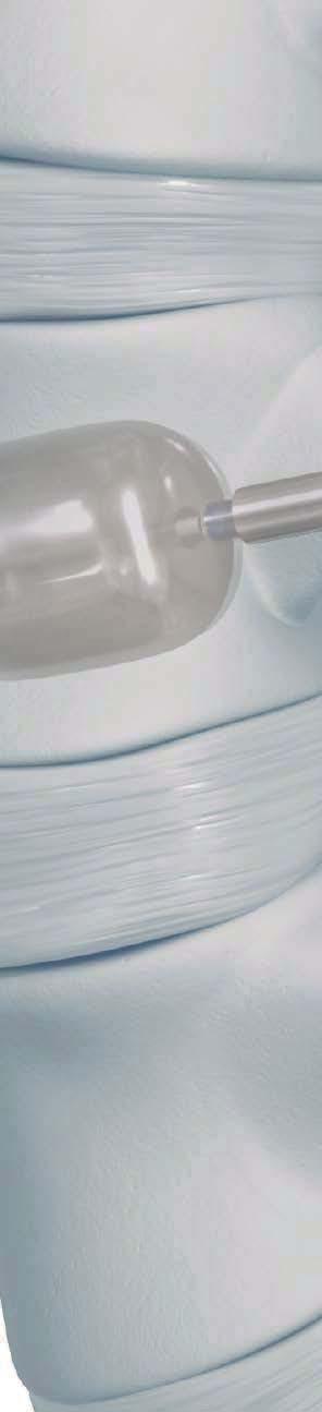
19 INFLATE THE SYNFLATE VERTEBRAL BALLOON BALLOON INSERTION Insert the balloon catheter under lateral radiographic control. The balloon is completely outside the working sleeve when white marking of the catheter shaft completely disappears into the working sleeve. Check the position under radiographic control and confirm the desired position under AP view. Notes: If it is not possible to completely insert the balloon catheter so that the white marking of the catheter shaft disappears, it may be necessary to clear the path again using the plunger. For insertion, the catheter stiffening wire must be mounted to the catheter. Check the balloon position by identifying the markers of the balloon under fluoroscopy in AP and lateral view. If the balloon experiences high friction in the working sleeve, pull the balloon back inside the working sleeve and try advancing again. CONNECT THE INFLATION SYSTEM(S) Connect the Inflation System to the side port of the catheter. Notes: The three-way stopcock supplied with the inflation system is not needed when using the SYNFLATE Vertebral Balloon. Do not connect the inflation system prior to catheter insertion; this may make the insertion difficult. Do not connect the inflation system to the Luer connection for the stiffening wire (back Luer). 18 DePuy Synthes SYNFLATE SYSTEM Surgical Technique

20 Inflate the SYNFLATE Vertebral Balloon BALLOON INFLATION To inflate the balloon, slowly rotate the handle of the inflation system clockwise while monitoring the pressure and volume. Proceed with inflation slowly, stopping every few seconds to allow the bone to adjust to the pressure/ volume changes. Use fluoroscopy to monitor balloon inflation. Stop increasing inflation when any of the following happen. The desired clinical outcome is reached Balloon touches anterior wall of vertebral body The pressure reaches 30 atm (440 psi) The maximum volume is achieved 4.0 ml for the small balloon 5.0 ml for the medium balloon 6.0 ml for the large balloon Inflation Chart (maximum recommended) S Small S Medium S Large Maximum Inflation Volume 4.0 ml 5.0 ml 6.0 ml Maximum Inflation Pressure 30 atm (440 psi) 30 atm (440 psi) 30 atm (440 psi) Unconstrained Inflation Chart (unconstrained test condition) S, Small S, Medium S Large Inflation Volume 8.1 ± 0.6 ml 11.2 ± 0.7 ml 14.5 ± 1.2 ml Inflation Pressure 8.1 ± 0.3 atm 7.2 ± 0.5 atm 6.4 ± 0.6 atm SYNFLATE SYSTEM Surgical Technique DePuy Synthes 19


21 Inflate the SYNFLATE Vertebral Balloon Note: Expansion of balloons, pressure and volume on the inflation system must be monitored carefully. Image shown reflects one possible condition where maximum pressure was reached and the inflation should be stopped. All criteria for stopping inflation are listed previously. Volume Precautions: The balloons may leak or burst if they are filled beyond their maximum volume or pressure. The performance of the balloon catheter may be adversely affected if it comes into contact with bone splinters, bone cement and/or surgical instruments. Pressure For bilateral procedures, inflate each balloon alternately in increments. Note: For bilateral procedures, it is important to ensure balloon inflation does not induce misalignment. As such, it may be necessary to inflate the balloons to different volumes to prevent or correct misalignment. 20 DePuy Synthes SYNFLATE SYSTEM Surgical Technique


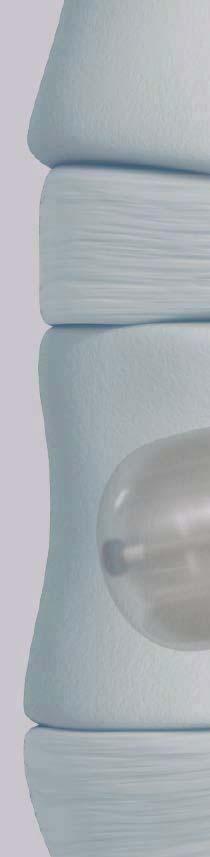
22 DEFLATE AND REMOVE Gradually decrease the pressure by turning the handle of the inflation system counterclockwise, until the manometer indicates approximately 10 atm (150 psi). Slide the wings forward while pulling the handle all the way back slowly. Wait a few seconds to fully collapse the balloon and draw a vacuum. Release the wings with the handle pulled all the way back, to seal the vacuum. Hold the working sleeve(s) in place and pull firmly on the catheters to retrieve the balloons. Note: If the balloon does not deflate, check the connections to the inflation system, draw a vacuum again, or assemble the vacuum syringe to draw a vacuum and collapse the balloon. Important: The balloon material is not implant-grade material. If balloon rupture occurs, visually inspect the ruptured balloon to confirm no fragment is missing from it. If any portion of the balloon is missing, it must be retrieved from the patient using general surgical instruments and surgeon discretion. Note: If it becomes difficult to remove the balloon catheter(s) through the working sleeve(s), twist the catheter counterclockwise while firmly pulling the catheter. If removal is still difficult, remove the balloon catheter(s) along with the working sleeve(s), then re-access the vertebral body using the working sleeve with the trocar assembly. Once re-access is complete, remove the trocar. Precaution: Only reinsert the stiffening wire when the balloon is outside the patient For bilateral procedures, deflate and retrieve each balloon alternately in increments. SYNFLATE SYSTEM Surgical Technique DePuy Synthes 21


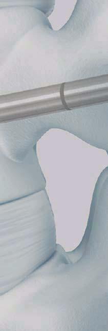
23 INJECT PMMA BONE CEMENT Instrument options S Access Kit, 10 Gauge, Diamond Tip, End Opening Clip Injection needle S S Access Kit, 10 Gauge, Bevel Tip, End Opening Access Kit, 10 Gauge, Diamond Tip, Side Opening S Access Kit, 10 Gauge, Bevel Tip, Side Opening Follow the manufacturers recommendations for PMMA use in the vertebral body. Starting marker Remove the injection needle assembled with the clip from package. Move the clip to the starting marker position. In this position, the distal tip of the injection needle is in line with the distal end of the working sleeve. Under fluoroscopy insert the injection needle with clip into the working sleeve and rotate the clip clockwise to lock it to the working sleeve. Note: Do not use the biopsy kit for cement application. 22 DePuy Synthes SYNFLATE SYSTEM Surgical Technique

24 Inject PMMA Bone Cement Connect a cement delivery system via the Luer lock. Note: The volume of the injection needle is 1 ml. For bilateral procedures, repeat on the contra-lateral side. Under lateral fluoroscopy, inject the PMMA cement. If using the side-opening needle, the direction of the cement flow can be changed by orienting the handle of the side-opening needle to correspond to the direction of the cement flow. The arrow on the handle of the side opening needle corresponds to the side of the opening. The cement should be contained within the vertebral body. Notes: When using an injection system other than VERTECEM V+ Syringe Kit, confirm that the system is compatible with the standard Luer lock on the injection needle. Hold the injection needle while disconnecting the syringe to prevent the injection needle from being disconnected from the side-opening needle. If using a bilateral approach, alternately fill both sides in increments. It is important to see the filling behavior of both needles. Once the filling of one side is accomplished, the lateral view of the opposite side is hidden by the cement, which makes monitoring the flow more difficult. SYNFLATE SYSTEM Surgical Technique DePuy Synthes 23

25 Inject PMMA Bone Cement Warning: Closely monitor the PMMA cement injection under fluoroscopy to reduce the risk of cement leakage. Severe leakage can cause death or paralysis. If cement leakage is observed during the procedure, STOP injecting and consider: waiting for the injected cement to harden, repositioning the needle, adjusting the needle direction, or stopping the procedure. If desired, continue cement injection slowly, and carefully evaluate for further leakage. If further leakage is observed, cease bone filler injection. Optional injection needle cleaning can be performed using the stylet contained in the single pack access kit. Refer to the manufacturer s instructions for proper waiting times required prior the removal of side-opening needle(s) and working sleeve(s). Warning: PMMA cement preparation, injection and setting times vary by product. Refer to manufacturer instructions prior to surgery and plan accordingly. If the injection needle with the working sleeve is removed too early, there may be a risk of pulling cement fibers into the muscle tissue. If this happens, cement residue should be removed from the soft tissues. Close the wound. Refer to IFU for side-opening needle for specific instructions for use, contraindications and warnings. 24 DePuy Synthes SYNFLATE SYSTEM Surgical Technique
26 POSTOPERATIVE CARE Place the patient in the supine position after surgery to compress the wound. Bruising may occur at the puncture sites. The patient may then be mobilized at the physician s discretion. SYNFLATE SYSTEM Surgical Technique DePuy Synthes 25
27 INSTRUMENTS SYNFLATE Vertebral Balloons Product No. Description Volume Initial length S Small 4 ml 10 mm S Medium 5 ml 15 mm S Large 6 ml 20 mm S Access Kit, 10G, Single Pack Diamond Tip, End Opening Contains: 1 Working sleeve 1 Trocar diamond tip 1 Plunger (not used with Cavity Creation Instrument) 1 Injection needle, End Opening with clip 1 Stylet 26 DePuy Synthes SYNFLATE SYSTEM Surgical Technique
28 Instruments S Access Kit, 10G, Single Pack Bevel Tip, End Opening Contains: 1 Working sleeve 1 Trocar bevel tip 1 Plunger (not used with Cavity Creation Instrument) 1 Injection needle, End Opening with clip 1 Stylet S Access Kit, 10G, Single Pack Diamond Tip, Side Opening Contains: 1 Working sleeve 1 Trocar diamond tip 1 Plunger (not used with Cavity Creation Instrument) 1 Injection needle, Side Opening with clip 1 Stylet SYNFLATE SYSTEM Surgical Technique DePuy Synthes 27

 1 Injection needle, Side Opening with clip 1")

29 Instruments S Access Kit, 10G, Single Pack Bevel Tip, Side Opening Contains: 1 Working sleeve 1 Trocar bevel tip 1 Plunger (not used with Cavity Creation Instrument) 1 Injection needle, Side Opening with clip 1 Stylet S Access Drill, 10G Contains: 1 Drill S Biopsy Kit, 10G Contains: 1 Biopsy needle 1 Stylet S Inflation System, sterile 28 DePuy Synthes SYNFLATE SYSTEM Surgical Technique
30 Limited Warranty and Disclaimer: DePuy Synthes Spine products are sold with a limited warranty to the original purchaser against defects in workmanship and materials. Any other express or implied warranties, including warranties of merchantability or fitness, are hereby disclaimed. WARNING: In the USA, this product has labeling limitations. See package insert for complete information. CAUTION: USA Law restricts these devices to sale by or on the order of a physician. Not all products are currently available in all markets. Synthes Spine 1302 Wrights Lane East West Chester, PA DePuy Synthes Spine, a division of DOI All rights reserved. J11968-A 6/13
SYNFLATE A balloon-based vertebral augmentation system.
 SYNFLATE A balloon-based vertebral augmentation system. This publication is not intended for distribution in the USA. TECHNIQUE GUIDE Image intensifier control Warning This description alone does not provide
Low Bend Distal Tibia Plates
 Part of the DePuy Synthes Locking Compression Plate (LCP ) System 3.5 mm LCP Low Bend Medial Distal Tibia Plates Surgical Technique Table of Contents Introduction 3.5 mm LCP Low Bend Medial Distal Tibia
3.5 mm LCP Olecranon Plates
 Part of the DePuy Synthes Locking Compression Plate (LCP ) System 3.5 mm LCP Olecranon Plates Surgical Technique Table of Contents Introduction 3.5 mm LCP Olecranon Plates 2 AO Principles 3 Indications
3.5 mm LCP Extra-articular Distal Humerus Plate
 Part of the DePuy Synthes Locking Compression Plate (LCP ) System 3.5 mm LCP Extra-articular Distal Humerus Plate Surgical Technique Table of Contents Introduction 3.5 mm LCP Extra-articular Distal Humerus
Thoracolumbar Spine Locking Plate (TSLP) System. A low-profile plating system for anterior stabilization of the thoracic and lumbar spine.
 System. A low-profile plating system for anterior stabilization of the thoracic and lumbar spine.") Thoracolumbar Spine Locking Plate (TSLP) System. A low-profile plating system for anterior stabilization of the thoracic and lumbar spine. Technique Guide Instruments and implants approved by the AO Foundation
Thoracolumbar Spine Locking Plate (TSLP) System. A low-profile plating system for anterior stabilization of the thoracic and lumbar spine. Technique Guide Instruments and implants approved by the AO Foundation
Trephine System. Principle-based anterior lumbar interbody fusion.
 Trephine System. Principle-based anterior lumbar interbody fusion. Technique Guide Instruments and implants approved by the AO Foundation Table of Contents Introduction Trephine System 2 AO Principles
ECD EXPANDABLE CORPECTOMY DEVICE Continuously Expandable Vertebral Body Replacement for Tumour Cases
 ECD EXPANDABLE CORPECTOMY DEVICE Continuously Expandable Vertebral Body Replacement for Tumour Cases Instruments and implants approved by the AO Foundation. This publication is not intended for distribution
DePuy International Ltd St Anthony s Road Leeds LS11 8DT England Tel: +44 (0) Fax: +44 (0)
 Fax: +44 (0)") Reference: 1. Data on file at DePuy Spine TM 2008 DePuy Spine International is a joint venture with Biedermann Motech, GmbH. This publication is not intended for distribution in the USA. X-ray on front
Reference: 1. Data on file at DePuy Spine TM 2008 DePuy Spine International is a joint venture with Biedermann Motech, GmbH. This publication is not intended for distribution in the USA. X-ray on front
3.5 mm Clavicle Hook Plates
 A Single Solution for Lateral Clavicle Fractures and Acromioclavicular Joint Dislocations 3.5 mm Clavicle Hook Plates Surgical Technique Discontinued December 2017 DSUS/TRM/1016/1126(1) Table of Contents
Technique Guide. ECD Expandable Corpectomy Device. Continuously Expandable Vertebral Body Replacement for Tumour Cases.
 Technique Guide ECD Expandable Corpectomy Device. Continuously Expandable Vertebral Body Replacement for Tumour Cases. Table of Contents Introduction Overview 2 AO ASIF Principles 4 Indications and Contraindications
PERFORATED CLICK X Augmentable pedicle screws for osteoporotic bone
 PERFORATED CLICK X Augmentable pedicle screws for osteoporotic bone Instruments and implants approved by the AO Foundation. This publication is not intended for distribution in the USA. SURGICAL TECHNIQUE
Surgical Technique & Product Catalogue. Guide for Open & MIS Procedures
 Surgical Technique & Product Catalogue Guide for Open & MIS Procedures INTRODUCTION The VIPER Cortical Fix Fenestrated Screw System is the first pedicle screw implant to offer enhanced fixation in both
Technique Guide. 3.5 mm LCP Low Bend Medial Distal Tibia Plates. Part of the Synthes locking compression plate (LCP) system.
 system.") Technique Guide 3.5 mm LCP Low Bend Medial Distal Tibia Plates. Part of the Synthes locking compression plate (LCP) system. Table of Contents Introduction 3.5 mm LCP Low Bend Medial Distal Tibia Plates
Technique Guide 3.5 mm LCP Low Bend Medial Distal Tibia Plates. Part of the Synthes locking compression plate (LCP) system. Table of Contents Introduction 3.5 mm LCP Low Bend Medial Distal Tibia Plates
Thoracolumbar Anterior Compression (TAC) System. Allows distraction, compression, and lateral fixation of the lower thoracic and lumbar spine.
 System. Allows distraction, compression, and lateral fixation of the lower thoracic and lumbar spine.") Thoracolumbar Anterior Compression (TAC) System. Allows distraction, compression, and lateral fixation of the lower thoracic and lumbar spine. Technique Guide Instruments and implants approved by the AO
Thoracolumbar Anterior Compression (TAC) System. Allows distraction, compression, and lateral fixation of the lower thoracic and lumbar spine. Technique Guide Instruments and implants approved by the AO
3.5 mm LCP Low Bend Medial Distal Tibia Plate Aiming Instruments
 Part of the 3.5 mm LCP 3.5 mm LCP Low Bend Medial Distal Tibia Plate Aiming Instruments Surgical Technique TABLE OF CONTENTS INTRODUCTION 3.5 mm LCP Low Bend Medial Distal Tibia Plate 2 Aiming Instruments
3.5 mm Locking Attachment Plate
 For Treatment of Periprosthetic Fractures 3.5 mm Locking Attachment Plate Surgical Technique Table of Contents Introduction 3.5 mm Locking Attachment Plate 2 Indications 4 Surgical Technique Preparation
Augmentable Pedicle Screws for Osteoporotic Bone. Perforated Click X. Surgical Technique
 Augmentable Pedicle Screws for Osteoporotic Bone Perforated Click X Surgical Technique Image intensifier control This description alone does not provide sufficient background for direct use of DePuy Synthes
Part of the DePuy Synthes Locking Compression Plate (LCP ) System. 3.5 mm LCP Medial Proximal Tibia Plates
 System. 3.5 mm LCP Medial Proximal Tibia Plates") Part of the DePuy Synthes Locking Compression Plate (LCP ) System 3.5 mm LCP Medial Proximal Tibia Plates Surgical Technique Table of Contents Introduction 3.5 mm LCP Medial Proximal Tibia Plates 2 AO
Part of the DePuy Synthes Locking Compression Plate (LCP ) System 3.5 mm LCP Medial Proximal Tibia Plates Surgical Technique Table of Contents Introduction 3.5 mm LCP Medial Proximal Tibia Plates 2 AO
Long Volar Plates for Diaphyseal-Metaphyseal Radius Fractures LCP. Dia-Meta Volar Distal Radius Plates. Surgical Technique
 Long Volar Plates for Diaphyseal-Metaphyseal Radius Fractures LCP Dia-Meta Volar Distal Radius Plates Surgical Technique Table of Contents Introduction LCP Dia-Meta Volar Distal Radius Plates 2 AO Principles
2.7 mm/3.5 mm LCP Distal Fibula Plate
 Part of the DePuy Synthes Locking Compression Plate (LCP ) System 2.7 mm/3.5 mm LCP Distal Fibula Plate Surgical Technique Table of Contents Introduction 2.7 mm/3.5 mm LCP Distal Fibula Plates 2 AO Principles
CSLP Quick Lock Screws. Preassembled expansionhead screw and locking screw for use with Cervical Spine Locking Plates (CSLP).
.") CSLP Quick Lock Screws. Preassembled expansionhead screw and locking screw for use with Cervical Spine Locking Plates (CSLP). Technique Guide Instruments and implants approved by the AO Foundation Table
CSLP Quick Lock Screws. Preassembled expansionhead screw and locking screw for use with Cervical Spine Locking Plates (CSLP). Technique Guide Instruments and implants approved by the AO Foundation Table
LCP Low Bend Medial Distal Tibia Plates 3.5 mm. Anatomic plates with low profile head for intra- and extraarticular fractures.
 LCP Low Bend Medial Distal Tibia Plates 3.5 mm. Anatomic plates with low profile head for intra- and extraarticular fractures. Surgical Technique This publication is not intended for distribution in the
3.5 mm LCP Clavicle Hook Plates
 Part of the Synthes Locking Compression Plate (LCP ) System 3.5 mm LCP Clavicle Hook Plates Surgical Technique Table of Contents Introduction 3.5 mm LCP Clavicle Hook Plates 2 AO Principles 4 Indications
Technique Guide. 3.5 mm LCP Low Bend Medial Distal Tibia Plate Aiming Instruments. Part of the 3.5 mm LCP Percutaneous Instrument System.
 Technique Guide 3.5 mm LCP Low Bend Medial Distal Tibia Plate Aiming Instruments. Part of the 3.5 mm LCP Percutaneous Instrument System. Table of Contents Introduction 3.5 mm LCP Low Bend Medial Distal
Luminary ALIF. Disc preparation and implant insertion instruments.
 Luminary ALIF. Disc preparation and implant insertion instruments. Technique Guide Instruments and implants approved by the AO Foundation Table of Contents Introduction Luminary ALIF 2 AO Principles 4
Replacement Device A modular expandable radiolucent vertebral body replacement system
 XRL Vertebral Body Replacement Device A modular expandable radiolucent vertebral body replacement system SURGICAL TECHNIQUE TABLE OF CONTENTS Introduction XRL System 2 AO Principles 5 Indications and Contraindications
Technique Guide. 3.5 mm LCP Olecranon Plates. Part of the Synthes locking compression plate (LCP) system.
 system.") Technique Guide 3.5 mm LCP Olecranon Plates. Part of the Synthes locking compression plate (LCP) system. Table of Contents Introduction 3.5 mm LCP Olecranon Plates 2 AO Principles 3 Indications 3 Clinical
Technique Guide 3.5 mm LCP Olecranon Plates. Part of the Synthes locking compression plate (LCP) system. Table of Contents Introduction 3.5 mm LCP Olecranon Plates 2 AO Principles 3 Indications 3 Clinical
Technique Guide. 3.5 mm LCP Proximal Tibia Plate. Part of the Synthes Small Fragment LCP System.
 Technique Guide 3.5 mm LCP Proximal Tibia Plate. Part of the Synthes Small Fragment LCP System. Table of Contents AO ASIF Principles of Internal Fixation 4 Indications/Contraindications 5 Surgical Technique
SpineJack. Ø 5.8 mm Ø 5.0 mm Ø 4.2 mm. Controlled Anatomical Restoration
 SpineJack Ø 5.8 mm Ø 5.0 mm Ø 4.2 mm Controlled Anatomical Restoration Introducing Controlled the Anatomical Surgical Restoration Technique SpineJack The SpineJack System is designed for the Anatomical
Technique Guide. T-PAL. Transforaminal posterior atraumatic lumbar spacer system.
 Technique Guide T-PAL. Transforaminal posterior atraumatic lumbar spacer system. Table of Contents Introduction T-PAL 2 AO Principles 4 Indications and Contraindications 5 Surgical Technique Preparation
Synex System TECHNIQUE GUIDE. An expandable vertebral body replacement device
 Synex System TECHNIQUE GUIDE An expandable vertebral body replacement device Original Instruments and Implants of the Association for the Study of Internal Fixation AO ASIF Synex System Overview The Synex
Technique Guide. LCP Proximal Femoral Hook Plate 4.5/5.0. Part of the LCP Periarticular Plating System.
 Technique Guide LCP Proximal Femoral Hook Plate 4.5/5.0. Part of the LCP Periarticular Plating System. Table of Contents Introduction Features and Benefits 2 AO ASIF Principles 4 Indications 5 Surgical
Orthopedic Bone Nail System - Distal Femoral Nail Surgical Technique Manual
 Orthopedic Bone Nail System - Distal Femoral Nail Surgical Technique Manual Note: The surgical procedures should be performed under the guidance of qualified skilled orthopedic surgeons, and this surgical
Mandible External Fixator II. Provides treatment for fractures of the maxillofacial area.
 Mandible External Fixator II. Provides treatment for fractures of the maxillofacial area. Technique Guide This publication is not intended for distribution in the USA. Instruments and implants approved
LCP Medial Distal Tibia Plate, without Tab. The Low Profile Anatomic Fixation System with Angular Stability and Optimal Screw Orientation.
 LCP Medial Distal Tibia Plate, without Tab. The Low Profile Anatomic Fixation System with Angular Stability and Optimal Screw Orientation. Technique Guide LCP Small Fragment System Table of Contents Introduction
Distal Radius Surgical Technique Guide
 Distal Radius Surgical Technique Guide About IlluminOss IlluminOss minimally invasive procedure incorporates a PET or Dacron balloon catheter that is delivered through a small pathway into the intramedullary
Cortoss Bone Augmentation Material. Surgical Technique Guide
 Cortoss Bone Augmentation Material Surgical Technique Guide Table of Contents System Overview... 1 Cortoss Components... 2 Aliquot Components... 3 Preparing Cortoss... 4, 5 Preparing the Vertebral Body...
VECTRA-T SURGICAL TECHNIQUE. The Translational Anterior Cervical Palate System. This publication is not intended for distribution in the USA.
 VECTRA-T The Translational Anterior Cervical Palate System This publication is not intended for distribution in the USA. SURGICAL TECHNIQUE Image intensifier control This description alone does not provide
Cannulated Pediatric Osteotomy System (CAPOS)
") A Single System of Osteotomy Blade Plates and Cannulated Instrumentation Cannulated Pediatric Osteotomy System (CAPOS) Surgical Technique Table of Contents Introduction Cannulated Pediatric Osteotomy System
A Single System of Osteotomy Blade Plates and Cannulated Instrumentation Cannulated Pediatric Osteotomy System (CAPOS) Surgical Technique Table of Contents Introduction Cannulated Pediatric Osteotomy System
Technique Guide. Insight Retractor. Minimal invasive access system to the posterior thoracolumbar spine.
 Technique Guide Insight Retractor. Minimal invasive access system to the posterior thoracolumbar spine. Table of Contents Introduction Insight Retractor 2 AO Principles 4 Indications and Contraindications
3.5 mm LCP Distal Humerus Plates
 Part of the DePuy Synthes Locking Compression Plate (LCP ) System 3.5 mm LCP Distal Humerus Plates Surgical Technique Table of Contents Introduction 3.5 mm LCP Distal Humerus Plates 2 AO Principles 4 Indications
Distal Radius Plate Instrument and Implant Set. Discontinued December 2017 DSUS/TRM/0916/1063(1)
") Distal Radius Plate Instrument and Implant Set Surgical Technique Discontinued December 2017 DSUS/TRM/0916/1063(1) The Distal Radius Plates Indications For fixation of fractures and osteotomies, including
Distal Radius Plate Instrument and Implant Set Surgical Technique Discontinued December 2017 DSUS/TRM/0916/1063(1) The Distal Radius Plates Indications For fixation of fractures and osteotomies, including
LCP Medial Proximal Tibial Plate 3.5. Part of the Synthes small fragment Locking Compression Plate (LCP) system.
 system.") LCP Medial Proximal Tibial Plate 3.5. Part of the Synthes small fragment Locking Compression Plate (LCP) system. Technique Guide This publication is not intended for distribution in the USA. Instruments
LCP Medial Proximal Tibial Plate 3.5. Part of the Synthes small fragment Locking Compression Plate (LCP) system. Technique Guide This publication is not intended for distribution in the USA. Instruments
Imbibe Bone marrow aspiration needle. Operative technique
 Imbibe Bone marrow aspiration needle Operative technique Imbibe Bone Marrow Aspiration Needle Imbibe Bone marrow aspiration needle Contents 1. Smart design... 3 2. Operative technique... 4 Posterior iliac
Conventus CAGE PH Surgical Techniques
 Conventus CAGE PH Surgical Techniques Conventus Orthopaedics The Conventus CAGE PH (PH Cage) is a permanent implant comprised of an expandable scaffold, made from nitinol and titanium, which is deployed
The Locking Calcaneal Plate Instrument and Implant Sets
 Part of the DePuy Synthes Locking Compression Plate (LCP ) System The Locking Calcaneal Plate Instrument and Implant Sets Surgical Technique Table of Contents Introduction Locking Calcaneal Plate 2 AO
COR. Precision Targeting Cartilage Repair System. Arthroscopic Technique for Repair of Osteochondral Defects
 COR Precision Targeting Cartilage Repair System Arthroscopic Technique for Repair of Osteochondral Defects Planning the Procedure An 18-gauge spinal needle is initially used to plan a perpendicular approach
TRUMATCH PERSONALIZED SOLUTIONS with the SIGMA High Performance Instruments
 TRUMATCH PERSONALIZED SOLUTIONS with the SIGMA High Performance Instruments Resection Guide System SURGICAL TECHNIQUE RESECTION GUIDE SURGICAL TECHNIQUE The following steps are an addendum to the SIGMA
Balloon in Balloon (BIB )
") Balloon in Balloon (BIB ) Stent Placement Catheter INSTRUCTIONS FOR USE CAUTION: FEDERAL (USA) LAW RESTRICTS THIS DEVICE TO SALE BY OR ON THE ORDER OF A PHYSICIAN. Read all instructions prior to use. Distributed
Balloon in Balloon (BIB ) Stent Placement Catheter INSTRUCTIONS FOR USE CAUTION: FEDERAL (USA) LAW RESTRICTS THIS DEVICE TO SALE BY OR ON THE ORDER OF A PHYSICIAN. Read all instructions prior to use. Distributed
XRL A modular expandable radiolucent vertebral body replacement system
 XRL A modular expandable radiolucent vertebral body replacement system This publication is not intended for distribution in the USA. SURGICAL TECHNIQUE Table of Contents Introduction XRL 2 AO Spine Principles
TSLP Thoracolumbar Spine Locking Plate
 Anterior thoracolumbar spine locking plate TSLP Thoracolumbar Spine Locking Plate Surgical Technique Image intensifier control This description alone does not provide sufficient background for direct use
Vertebral Compression Fracture System. AFFIRM Vertebral Compression Fracture System 11
 Affirm Vertebral Compression Fracture System VERTEBRAL AUGMENTATION Surgical Technique AFFIRM Vertebral Compression Fracture System 11 A Division of Globus Medical At Algea Therapies, we are committed
3.5 mm LCP Hook Plate
 Part of the DePuy Synthes Locking Compression Plate (LCP ) System 3.5 mm LCP Hook Plate Surgical Technique Table of Contents Introduction 3.5 mm LCP Hook Plate 2 AO Principles 4 Indications 5 Clinical
Surgical Technique Guide
 Sacroiliac Joint Fusion System Surgical Technique Guide Moving Life Forward Table of Contents SiCure Implant Overview...2 SiCure System Information...3 X-ray Basics...4 Patient Positioning....5 Surgical
Technique Guide. 2.7 mm/3.5 mm LCP Distal Fibula Plates. Part of the Synthes locking compression plate (LCP) system.
 system.") Technique Guide 2.7 mm/3.5 mm LCP Distal Fibula Plates. Part of the Synthes locking compression plate (LCP) system. Table of Contents Introduction 2.7 mm/3.5 mm LCP Distal Fibula Plates 2 AO Principles
Technique Guide 2.7 mm/3.5 mm LCP Distal Fibula Plates. Part of the Synthes locking compression plate (LCP) system. Table of Contents Introduction 2.7 mm/3.5 mm LCP Distal Fibula Plates 2 AO Principles
Mini External Fixator
 Stabilize the Phalanges and Metacarpals Mini External Fixator Surgical Technique Table of Contents Introduction Mini External Fixator 2 Indications 4 Surgical Technique Technique Overview 5 Product Information
Lag Screw Device Intended for symphyseal fracture fixation of the mandible
 Lag Screw Device Intended for symphyseal fracture fixation of the mandible SUrgicaL TecHNiqUe Lag Screw Device Intended for symphyseal fracture fixation of the mandible Simplifies the lag screw fixation
TECHNICAL BROCHURE. Capture Facet Fixation System
 TECHNICAL BROCHURE Capture Facet Fixation System Table of Contents Product Overview...2 Instruments...4 Capture Facet Screw Surgical Technique Patient Preparation and Positioning...6 Guide Pin Placement...7
3.5 mm LCP Distal Tibia T-Plates
 Part of the DePuy Synthes Locking Compression Plate (LCP ) System 3.5 mm LCP Distal Tibia T-Plates Surgical Technique Table of Contents Introduction 3.5 mm LCP Distal Tibia T-Plates 2 AO Principles 4 Indications
Occipital Cervical Fusion System. Implants and instruments designed to optimize fixation to the occiput.
 Occipital Cervical Fusion System. Implants and instruments designed to optimize fixation to the occiput. Technique Guide and implants approved by the AO Foundation Table of Contents Introduction Occipital
USS Variable Axis Screw (VAS) System. For posterior fixation of the lumbar spine.
 System. For posterior fixation of the lumbar spine.") USS Variable Axis Screw (VAS) System. For posterior fixation of the lumbar spine. Technique Guide Instruments and implants approved by the AO Foundation Table of Contents Introduction USS Variable Axis
USS Variable Axis Screw (VAS) System. For posterior fixation of the lumbar spine. Technique Guide Instruments and implants approved by the AO Foundation Table of Contents Introduction USS Variable Axis
TELEFIX SURGICAL TECHNIQUE. Implant system for the anterior stabilization of the thoracolumbar spine
 TELEFIX Implant system for the anterior stabilization of the thoracolumbar spine Instruments and implants approved by the AO Foundation. This publication is not intended for distribution in the USA. SURGICAL
The Versatile Polyaxial Solution for the Universal Spine Systems. USS II Polyaxial. Surgical Technique
 The Versatile Polyaxial Solution for the Universal Spine Systems USS II Polyaxial Surgical Technique Image intensifier control This description alone does not provide sufficient background for direct use
4.5 mm LCP Medial Proximal Tibia Plates
 Part of the DePuy Synthes LCP Periarticular Plating System 4.5 mm LCP Medial Proximal Tibia Plates Surgical Technique Table of Contents Introduction 4.5 mm LCP Medial Proximal Tibia Plates 2 AO Principles
3. PATIENT POSITIONING & FRACTURE REDUCTION 3 8. DISTAL GUIDED LOCKING FOR PROXIMAL NAIL PROXIMAL LOCKING FOR LONG NAIL 13
 Contents IMPLANT FEATURES 2 1. INDICATIONS 3 2. PRE-OPERATIVE PLANNING 3 3. PATIENT POSITIONING & FRACTURE REDUCTION 3 4. INCISION 4 5. ENTRY POINT 4-6 6. PROXIMAL NAIL INSERTION 6-7 7. PROXIMAL LOCKING
CSLP-Cervical Spine Locking Plate
 For anterior, cervical fixation CSLP-Cervical Spine Locking Plate Surgical Technique Image intensifier control This description alone does not provide sufficient background for direct use of DePuy Synthes
TABLE OF CONTENTS. 2 (8144 Rev 2)
") 1 (8144 Rev 2) TABLE OF CONTENTS Introduction Conventus CAGE TM - Proximal Humerus...3 Indications and Contraindications...4 Surgical Summary...5 Patient Positioning & Approach...6 Surgical Technique Plate
1 (8144 Rev 2) TABLE OF CONTENTS Introduction Conventus CAGE TM - Proximal Humerus...3 Indications and Contraindications...4 Surgical Summary...5 Patient Positioning & Approach...6 Surgical Technique Plate
ARCH Laminoplasty System. Dedicated System for Open-door Laminoplasty.
 ARCH Laminoplasty System. Dedicated System for Open-door Laminoplasty. Surgical Technique This publication is not intended for distribution in the USA. Instruments and implants approved by the AO Foundation.
Quick Reference Guide
 Quick Reference Guide Indications for Use The AFX Endovascular AAA System is indicated for endovascular treatment in patients with AAA. The devices are indicated for patients with suitable aneurysm morphology
1 Description. 2 Indications. 3 Warnings ASPIRATION CATHETER
 Page 1 of 5 ASPIRATION CATHETER Carefully read all instructions prior to use, observe all warnings and precautions noted throughout these instructions. Failure to do so may result in complications. STERILE.
For Distal Femur Fractures. 95º Condylar Plate. Quick Reference Chart
 For Distal Femur Fractures 95º Condylar Plate Quick Reference Chart 95 Condylar Plate. Quick reference chart for distal femur fractures. Insert guide wires Fix condylar fragments with 6.5 mm cancellous
Control. Control Through VISCOSITY Control Through DELIVERY Control Through SIMPLICITY
 Control. Now that s CONFIDENCE. Control Through VISCOSITY Control Through DELIVERY Control Through SIMPLICITY Control throughviscosity Controlled Fill Cement Interdigitation Low viscosity cement Trabecular
Titanium Distal Femoral Nail System
 For Retrograde Insertion Titanium Distal Femoral Nail System Surgical Technique Table of Contents Introduction Titanium Distal Femoral Nail System 2 AO Principles 4 Indications 5 Clinical Cases 6 Surgical
Large Distractor Femur
 Fracture Reduction and Provisional Stabilization Large Distractor Femur Surgical Technique Table of Contents Introduction Standard Femoral Distraction 2 Large Distractor System 4 Surgical Technique Prepare
mild Devices Kit - Instructions for Use
 INDICATION FOR USE The Vertos mild Devices are specialized surgical instruments intended to be used to perform lumbar decompressive procedures for the treatment of various spinal conditions. CONTENTS AND
Bone Preservation Stem
 TRI-LOCK Bone Preservation Stem Featuring GRIPTION Coating Surgical Technique Implant Geometry Extending the TRI-LOCK Stem heritage The original TRI-LOCK Stem was introduced in 1981. This implant was
System. Humeral Nail. Surgical Technique
 System Humeral Nail Surgical Technique Contents IMPLANT FEATURES 2 1. INDICATIONS 3 2. PRE-OPERATIVE PLANNING 3 3. PATIENT POSITIONING & FRACTURE REDUCTION 3 4. INCISION 4 5. ENTRY POINT 4-6 6. PROXIMAL
3.5 MM VA-LCP PROXIMAL TIBIA PLATE SYSTEM
 3.5 MM VA-LCP PROXIMAL TIBIA PLATE SYSTEM Part of the DePuy Synthes Variable Angle Periarticular Plating System SURGICAL TECHNIQUE TABLE OF CONTENTS INTRODUCTION 3.5 mm VA-LCP Proximal Tibial Plate 2 AO
Instruction for Use of Kyphoplasty Tool Kit JS-CE-SM-07-01,A/0
 Instruction for Use of Kyphoplasty Tool Kit JS-CE-SM-07-01,A/0 1 Instruction for Use of Kyphoplasty Tool Kit Product name Kyphoplasty Tool Kit Product structure and components Kyphoplasty Tool Kit consists
Technique Guide. ARCH Laminoplasty System. Dedicated System for Open-door Laminoplasty.
 Technique Guide ARCH Laminoplasty System. Dedicated System for Open-door Laminoplasty. Table of Contents Introduction Overview 2 AO ASIF Principles 4 Indications and Contraindications 5 Product Information
Low Profile Neuro Plating System. Surgical Technique
 Low Profile Neuro Plating System Surgical Technique TABLE OF CONTENTS INTRODUCTION Low Profile Neuro Plating System 2 SURGICAL TECHNIQUE Technique 5 PRODUCT INFORMATION Low Profile Neuro Plates 10 Low
3.5 mm LCP Anterolateral Distal Tibia Plates
 Part of the DePuy Synthes Locking Compression Plate (LCP ) System 3.5 mm LCP Anterolateral Distal Tibia Plates Surgical Technique Table of Contents Introduction 3.5 mm LCP Anterolateral Distal Tibia Plates
PFNA. With Augmentation Option.
 PFNA. With Augmentation Option. Superior anchor in osteoporotic bone Simple and reproducible procedure through standardized technique Intraoperative decision for augmentation This publication is not intended
RESECTION GUIDE SYSTEM. TRUMATCH Personalized Solutions Surgical Technique with ATTUNE Knee INTUITION Instruments
 RESECTION GUIDE SYSTEM TRUMATCH Personalized Solutions Surgical Technique with ATTUNE Knee INTUITION Instruments RESECTION GUIDE SURGICAL TECHNIQUE The following steps are an addendum to the ATTUNE Knee
Patella Planing System
 REFERENCE GUIDE AND SURGICAL TECHNIQUE Patella Planing System SPECIALIST INSTRUMENTS AN ONLAY PATELLA PREPARATION SYSTEM TECHNIQUE FOR PRIMARY PATELLAR RESURFACING The Specialist 2 Patellar Planer System
Distal Radius Sterile Kit. Optimization And Efficiency You Can Rely On
 Distal Radius Sterile Kit Optimization And Efficiency You Can Rely On Introducing The Distal Radius Sterile Kit Improved OR Workflow The Distal Radius Sterile Kit provides high-quality single-use implants
3.5 mm LCP Superior Anterior Clavicle Plates
 Part of the DePuy Synthes Locking Compression Plate (LCP ) System 3.5 mm LCP Superior Anterior Clavicle Plates Surgical Technique Table of Contents Introduction 3.5 mm LCP Superior Anterior Clavicle Plates
low ProfIle neuro PlaTIng system
 low ProfIle neuro PlaTIng system surgical TeChnIque Table of Contents Introduction Low Profile Neuro Cranial Plating System 2 Surgical Technique Technique 5 Product Information Low Profile Neuro Plates
PROXIMAL FEMORAL NAIL REMOVAL SET
 PROXIMAL FEMORAL NAIL REMOVAL SET for PFN, TFN and PFNA/PFNA-II Instruments and Implants approved by the AO Foundation. This publication is not intended for distribution in the USA. SURGICAL TECHNIQUE
100 Interpace Parkway Parsippany, NJ
 100 Interpace Parkway Parsippany, NJ 07054 www.biometspine.com 800-526-2579 All trademarks are the property of Biomet, Inc. or one of its subsidiaries, unless otherwise indicated. Rx Only. 2009 EBI, LLC.
OBSOLETED. LCP Medial Distal Tibia Plate, without Tab. The Low Profile Anatomic Fixation System with Angular Stability and Optimal Screw Orientation.
 LCP Medial Distal Tibia Plate, without Tab. The Low Profile Anatomic Fixation System with Angular Stability and Optimal Screw Orientation. Surgical Technique LCP Small Fragment System This publication
LCP Anterolateral Distal Tibia Plate 3.5. The low profile anatomic fixation system with optimal plate placement and angular stability.
 LCP Anterolateral Distal Tibia Plate 3.5. The low profile anatomic fixation system with optimal plate placement and angular stability. Technique Guide LCP Small Fragment System Table of Contents Introduction
FACET WEDGE. Facet joint fixation device.
 FACET WEDGE. Facet joint fixation device. Technique Guide Synthes FACET WEDGE Technique Guide /44 Synthes FACET WEDGE Technique Guide /44 Table of Contents Introduction FACET WEDGE 3 AO Principles 4 Indications
The CerviFix System. Including the StarLock Components. CerviFix Clamp and Screw. StarLock Clamp and Screw
 The CerviFix System Including the StarLock Components CerviFix Clamp and Screw StarLock Clamp and Screw The CerviFix System The CerviFix System is a comprehensive set of implants, including clamps, screws,
LCP Anterolateral Distal Tibia Plate 3.5. The low profile anatomic fixation system with optimal plate placement and angular stability.
 LCP Anterolateral Distal Tibia Plate 3.5. The low profile anatomic fixation system with optimal plate placement and angular stability. Technique Guide LCP Small Fragment System Table of Contents Introduction
2.4 mm Variable Angle LCP Volar Extra-Articular Distal Radius System. For fragment-specific fracture fixation with variable angle locking technology.
 Technique Guide 2.4 mm Variable Angle LCP Volar Extra-Articular Distal Radius System. For fragment-specific fracture fixation with variable angle locking technology. Table of Contents Introduction 2.4
Technique Guide. C1/C2 Access System. Percutaneous transarticular screw fixation.
 Technique Guide C1/C2 Access System. Percutaneous transarticular screw fixation. C1/C2 Access System Table of Contents General introduction 2 Indications/Contraindications 2 Image intensifier-assisted
RECOMMENDED INSTRUCTIONS FOR USE
 Rapid Exchange PTCA Dilatation Catheter RECOMMENDED INSTRUCTIONS FOR USE Available in diameters 1.25mm to 4.5mm and in lengths 09mm to 40mm Caution: This device should be used only by physicians trained
VA-LCP Anterior Clavicle Plate. The anatomically precontoured fixation system with angular stability for clavicle shaft and lateral clavicle.
 Technique Guide VA-LCP Anterior Clavicle Plate. The anatomically precontoured fixation system with angular stability for clavicle shaft and lateral clavicle. Table of Contents Introduction VA-LCP Anterior
Titanium Wire With Barb and Needle
 For Canthal Tendon Procedures Titanium Wire With Barb and Needle Surgical Technique Table of Contents Introduction Titanium Wire With Barb and Needle 2 Indications 2 Surgical Technique Preoperative Planning